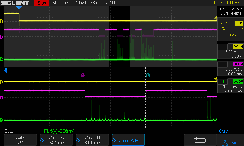
It’s measured over the active time of the laser pulse during the test pattern.
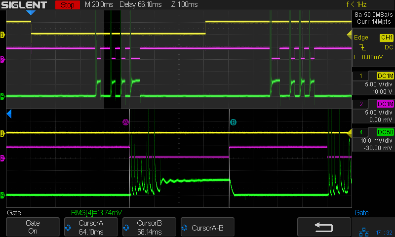
My first thought was to capture those huge peaks, but the 100 mA/div scale pushed the rest of the pulse down into the noise:
The A and B cursors mark the RMS calculation gate time when the Enable / L-ON signal (magenta) is low.
So I cranked up the gain enough to see the tube current controlled by the PWM:
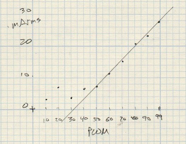
Plotting the measured RMS value against the PWM duty cycle input:
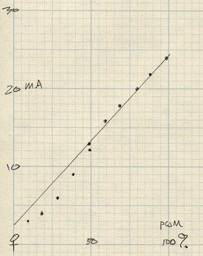
Because the tube current is mostly spikes below about 25% PWM, the lower RMS values don’t match that part of the plot from the power supply’s meter:
But everything matches closely enough to say that, yeah, that’s pretty much how the power supply behaves.
For completeness, a description of the test setup and scope traces:
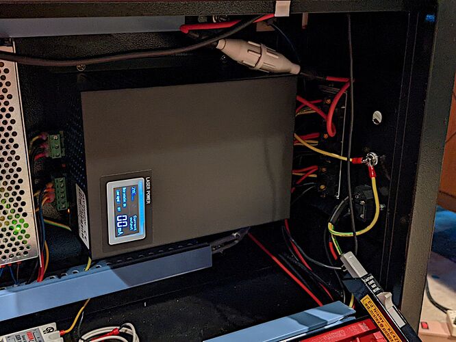
That’s the Tek current probe clipped around the tube’s cathode wire near the power supply.
