Here is a chart for tube lengths, wattage and mA…
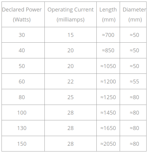
It suggests the same ‘ballpark’ for mA as I use…
![]()
The writer says there are 3xx hours on his tube. I had about 50 hours on my K40 tube, ran it with an ammeter, never going over 15 mA. Then I started getting two beams in my work and traced it all the way back to the tube itself. Had to replace it. My beam spot is almost imperceptibly small, maybe 0.2 mm. Cuts like a knife. I attribute this to a making my laser head adjustable up and down (Z axis) and better focused. Check the beam at the first mirror, should only be one, and be very, very fine.
Just reading this thread and i think i have my head around it but there’s seems to be people here that are missing the point that @jkwilborn is trying to make.
Correct me if I’m wrong but i believe you need to ensure that you calculate the current your running using the power percentage and the ammeter reading. Not just the ammeter.
As the pwm signal is made up of 5v pulses no matter what your power percentage setting is the laser is getting 100% of the current the power supply will allow, just for less time.
So from the table jkwilborn posted if you’re ammeter is reading 16mA at 50% that equates to 32mA that the laser is seeing for every 5v pulse. The max on the table above is 20mA (50w). The graph animation on the webpage below might help.
Www dot - - quora.com/How-do-we-calculate-the-PWM-time-period
I think jkwilborn said it very clearly but noone has seemed to taken it in. It sounds to me like your current was too high and thats why the tube died prematurely and the new one will do the same if you don’t adjust the current.
Am i understanding this correctly, maybe there is something i am missing??
Update time!
First I contacted the supplier of the tube and confirmed that the ratings card is devised by setting a limit on the PSU current (in the case of my tube, 12mA) and then running it at 20, 50 and 99% duty cycle, and capturing the laser energy output with a laser power meter.
I spent about 2 hours with a scope and got readings that did not make sense. We put a 1KOhm resistor in series with the tube and put the probe across that. Dividing the measured voltage by 1000 gave a current-time graph. Across a 100ms pulse, the first 10ms or so would spike to 32mA then quickly settle to 4-5mA no matter the duty cycle. I will parse the CSV data and supply a graph here later.
The tube actually lases at 12% duty cycle, so I am cutting at 20% (just cuts 3mm MDF at 10mm/s). I feel that the safety margin is sufficient, but I do not know this for sure. I may very well still be overdriving the tube.
====
In testing the tube, I found a point at about 30% where the nature of the discharge visible through the tube changes. Between 12-25% there is a purplish transparent beam inside the tube. Around 28% a more ‘solid’ ‘core’ forms within that beam and the laser makes a louder hissing/tearing noise at the point of cut - this ‘core’ is unstable and lasts about 5-8 seconds from ignition. At about 30% and above the ‘core’ is much more stable. It’s an interesting phenomenon that I found mention of a while ago but can’t seem to find where. And I can’t formulate a search term to find out more about it. What exactly is going on here?
Which agrees with what I measured some time ago. Basically, the power supply acts as an analog current limiter controlled by the low-pass filtered PWM input, so that the tube current is not full-on during the high part of the PWM cycle.
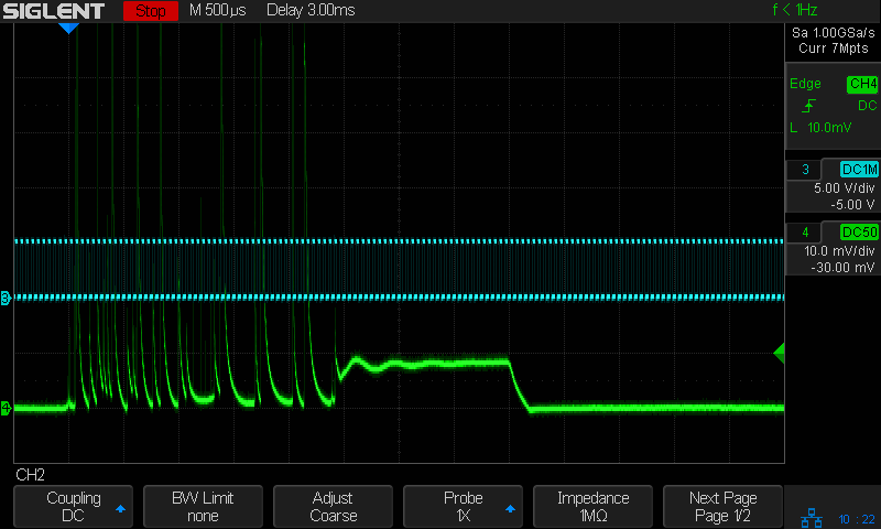
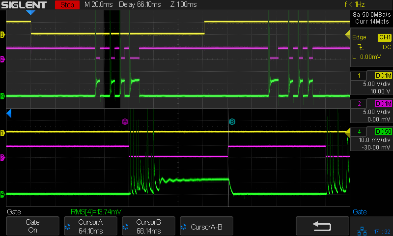
For example, the 40% PWM input is the cyan square wave at 20 kHz and the laser tube current is the green trace at 10 mA/div:
The current eventually settles down to about 8 mA, roughly 40% of the supply’s maximum 25-ish mA.
The hash in the beginning of the pulse seems to be the tube starting to conduct and, even though it looks horrible, the average current is just about 8 mA.
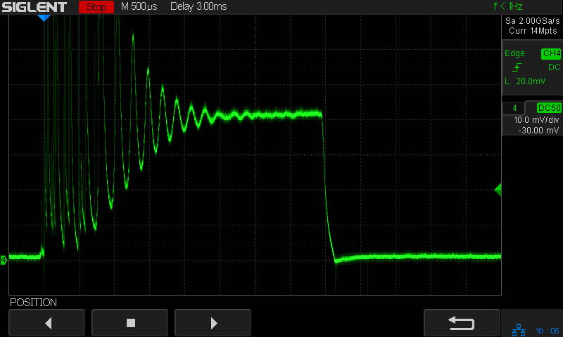
Here’s a pulse at 80% PWM with the current at 5 mA/div:
The pulse settles down to 22 mA, suggesting the power supply max is 27 mA. OMTech sent it as a replacement for the failed supply in my 60 W laser, but it’s definitely running higher than I expected.
I have a bunch of blog posts going into far more detail than might be reasonable, but the effect remains consistent: there is no trace of the digital PWM input in the power supply’s output current.
Yes my results are exactly consistent with yours - waveform is the same shape.
I get a weirdly spiking current that then settles down after a short while, except that it doesn’t in my case as I have a 40W power supply driving a 50W tube apparently (and I only tested up to about 50% PWM)
I’ll do a full power pulse a few times and check what the maximum current the power supply is set to - will be looking out for a waveform similar to the last image of yours
Then my plan is to test increasing PWM percentage until I get one that corresponds to say 10mA and use that as my maximum value (as the tube was tested at 12mA)
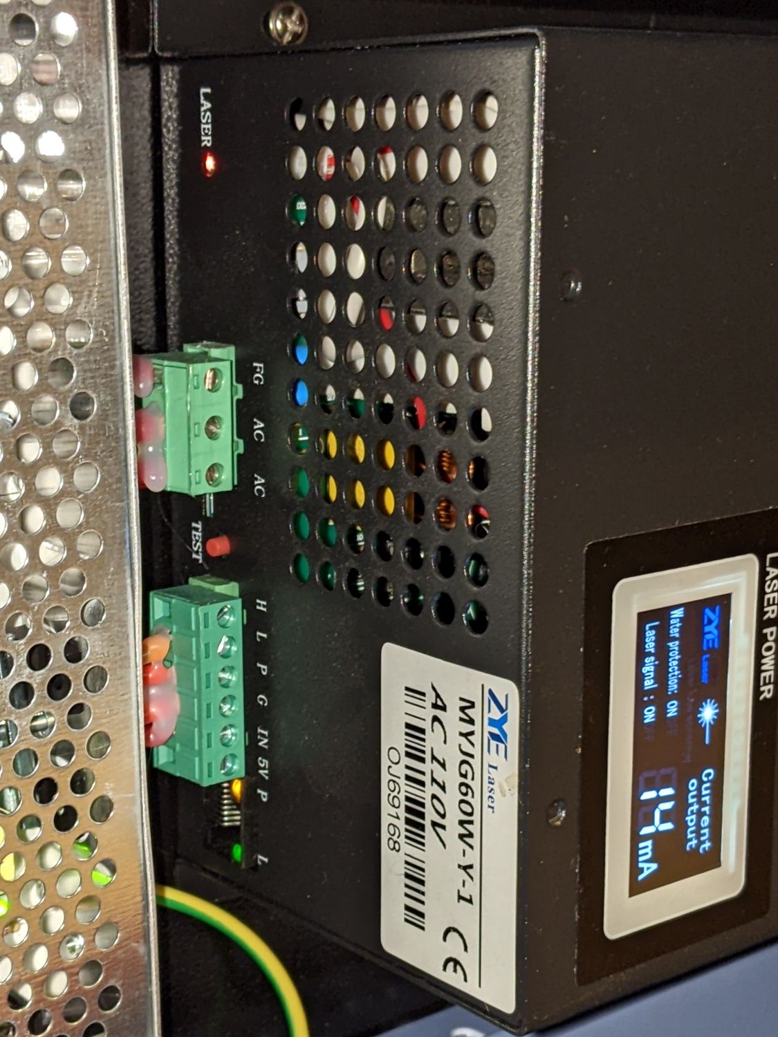
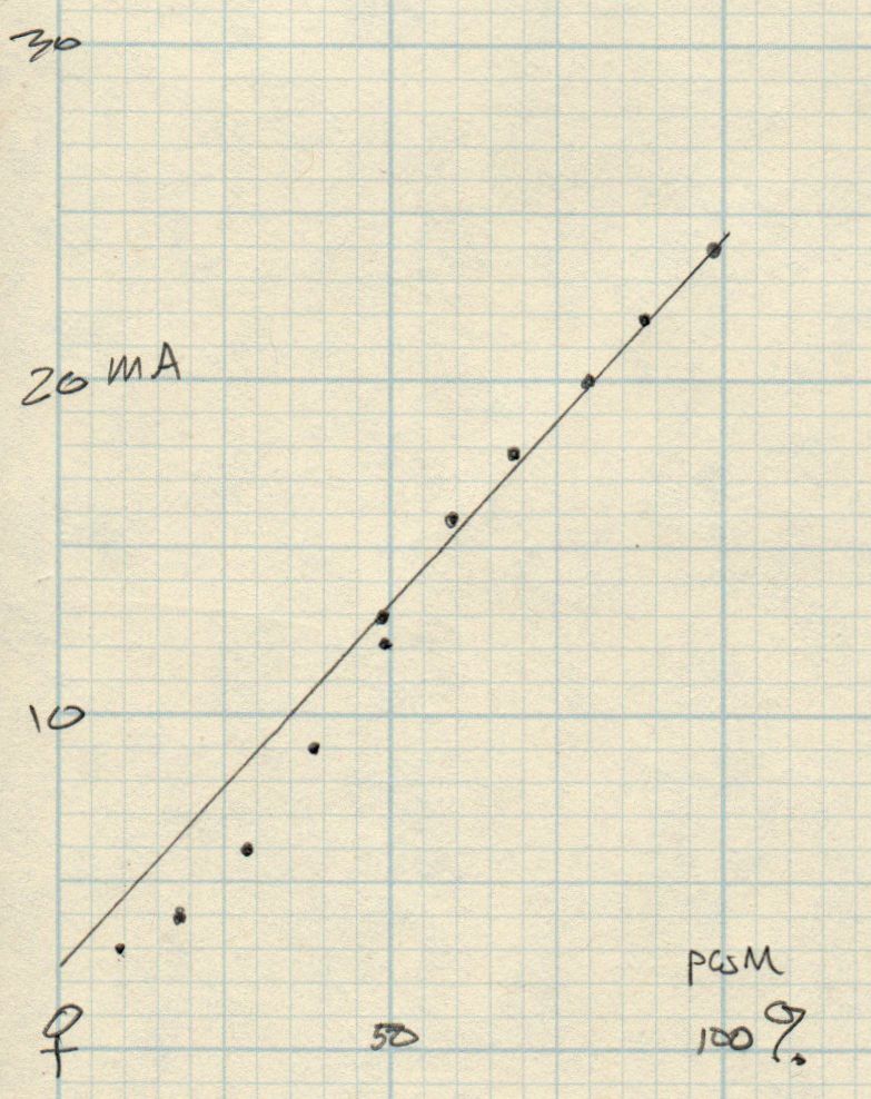
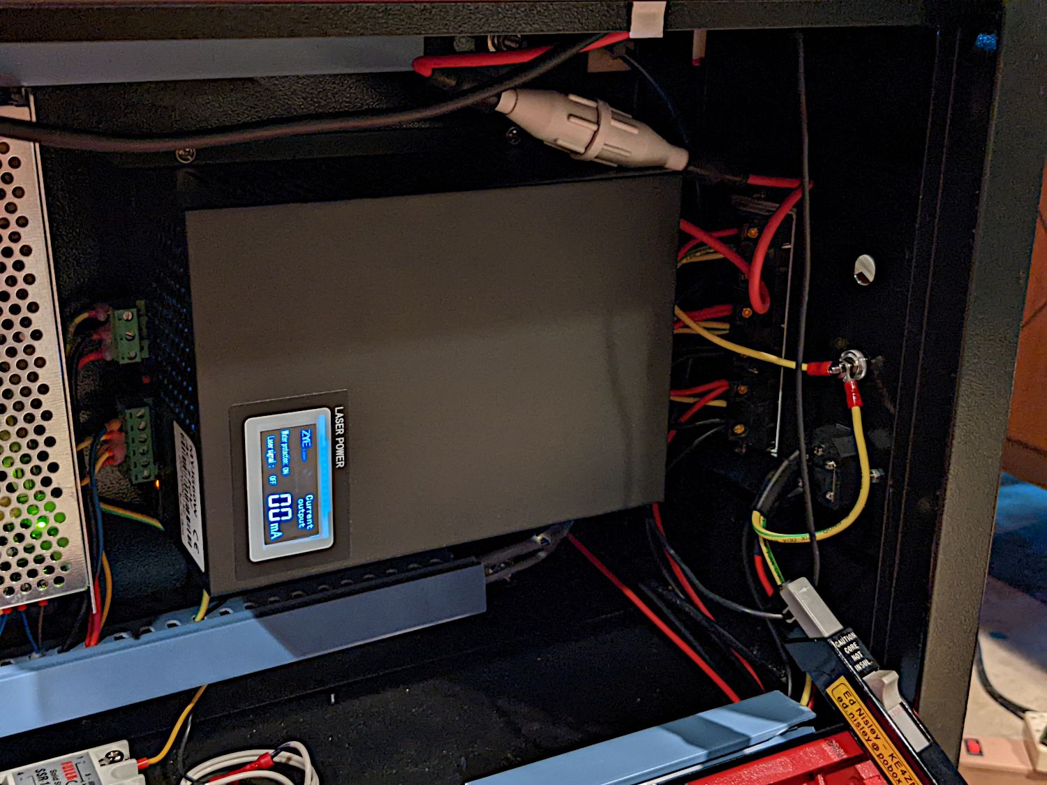
The power supply here has a digital milliammeter that (pretty much) agrees with the current measured at the tail of long manual pulses with my Tek current probe:
I think Sadler used “preionization” to describe the tube’s behavior at low currents. That might account for the hash at the start of each pulse, as well as the continuous hash below about 25% PWM.
If you have a mA meter you can run it at 50% pwm, continuous and it will read 50% of your lps current setting… no need to run 100% unless you are curious…
@ednisley first current trace shows the current going off the screen ?
![]()
Yes, those initial peaks are breathtakingly high.
The scale is 10 mA/div, so they’re well in excess of 80 mA. The power supply controls the average current to whatever the PWM calls for, but doesn’t limit the peak current.
If the pulse is long enough for the tube to fully ignite / ionize / lase / whatever the term might be, then the current settles down to a nice-looking line. Pulses less than a few milliseconds never settle down and consist of those huge, irregularly spaced peaks from beginning to end.
Please explain… average based on what? An average has to be over a time period, what period are we expecting?
![]()
It’s measured over the active time of the laser pulse during the test pattern.
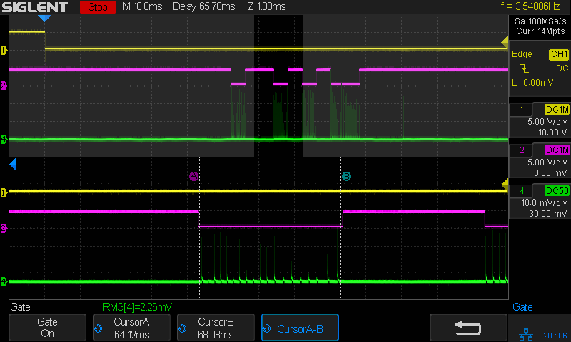
My first thought was to capture those huge peaks, but the 100 mA/div scale pushed the rest of the pulse down into the noise:
The A and B cursors mark the RMS calculation gate time when the Enable / L-ON signal (magenta) is low.
So I cranked up the gain enough to see the tube current controlled by the PWM:
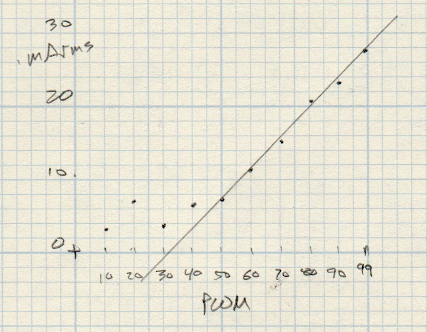
Plotting the measured RMS value against the PWM duty cycle input:
Because the tube current is mostly spikes below about 25% PWM, the lower RMS values don’t match that part of the plot from the power supply’s meter:
But everything matches closely enough to say that, yeah, that’s pretty much how the power supply behaves.
For completeness, a description of the test setup and scope traces:
That’s the Tek current probe clipped around the tube’s cathode wire near the power supply.
From the look of the first ‘pencil’ graph, you can’t really lase below about 8% pwm … ?
Is this the same lps with that the other screenshots came from?
Sure like that probe… Their cost, makes the scope itself a low cost part ![]()
I’ve got one I’m working on, but it will never be up to the level of a commercial probe. I think I’ll just build it to be a permanent addition to the machine with it’s own output.
It’s working now, but is really susceptible to surrounding magnetic fields, especially the earths… ![]()
I also need to limit it’s bandwidth…
Thanks for the screenshots…
73’s
![]()
IIRC, the Ruida controller arrived with a lower cutoff at 10%, I lowered it to 5% to see what really low powers would be like. Turns out the tube didn’t light up until around 7%, so I set the minimum at 8% and left it there.
OMTech sent this supply as a replacement for the one that failed, but I also bought a Cloudray. Some quick measurements showed both behaved pretty much the same way, so the Cloudray sits on the top shelf as a cold backup.
I got the Tek current probes & amps long before they became eBay collectibles, so they’re not quite so bling as they seem. I should’a bought more: they’re definitely outperforming some other “investments”! ![]()
The probe clamps a mirror-polished split ferrite core around the conductor, with a transformer winding boosting the signal. The amp senses the current, then feeds a fraction back into the transformer to buck the input current and prevent core saturation, all with a 20 MHz bandwidth. I’ve spent a long time pondering the schematics and they’re a wonder to behold.