Use a target on mirror 1 (m1). Use only enough power for a brown spot.
There is a link when the text is blue… click on the TEM0
![]()
Use a target on mirror 1 (m1). Use only enough power for a brown spot.
There is a link when the text is blue… click on the TEM0
![]()
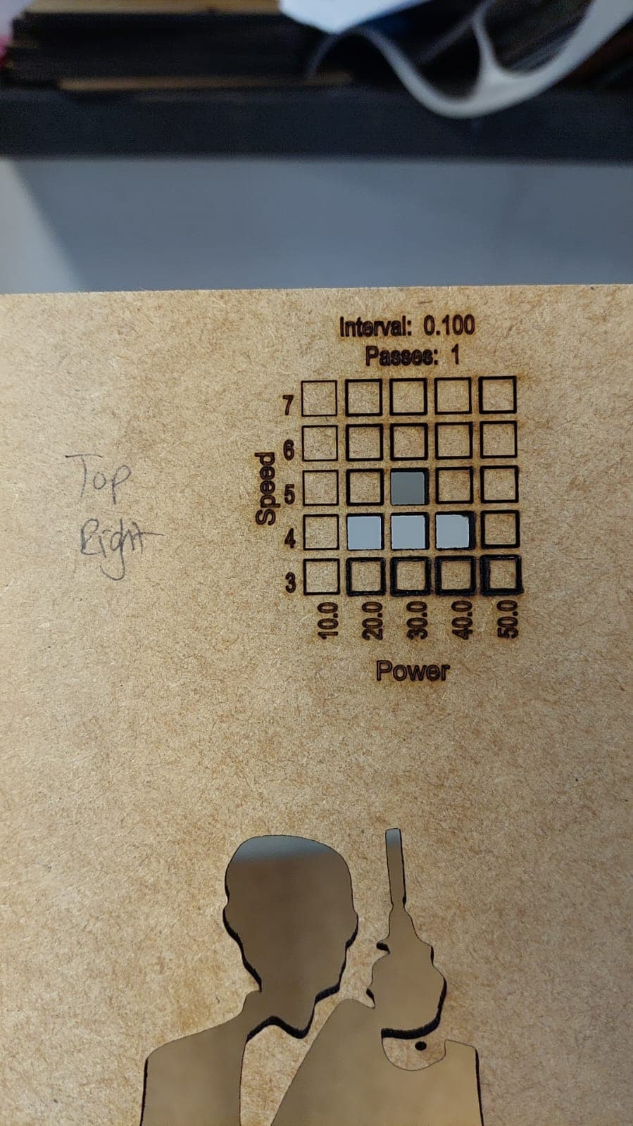
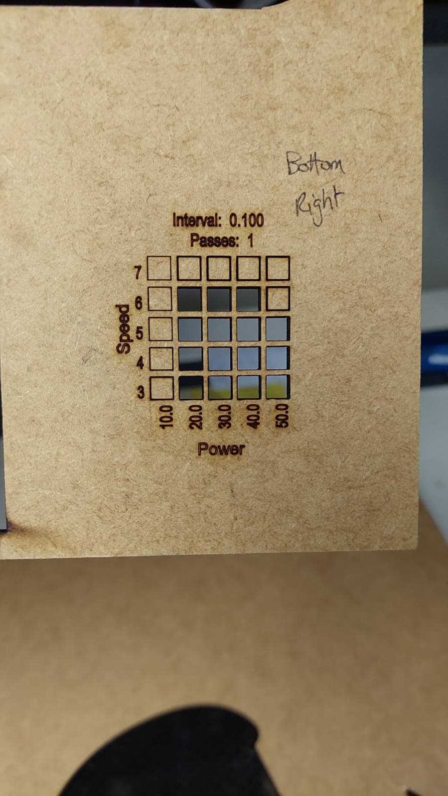
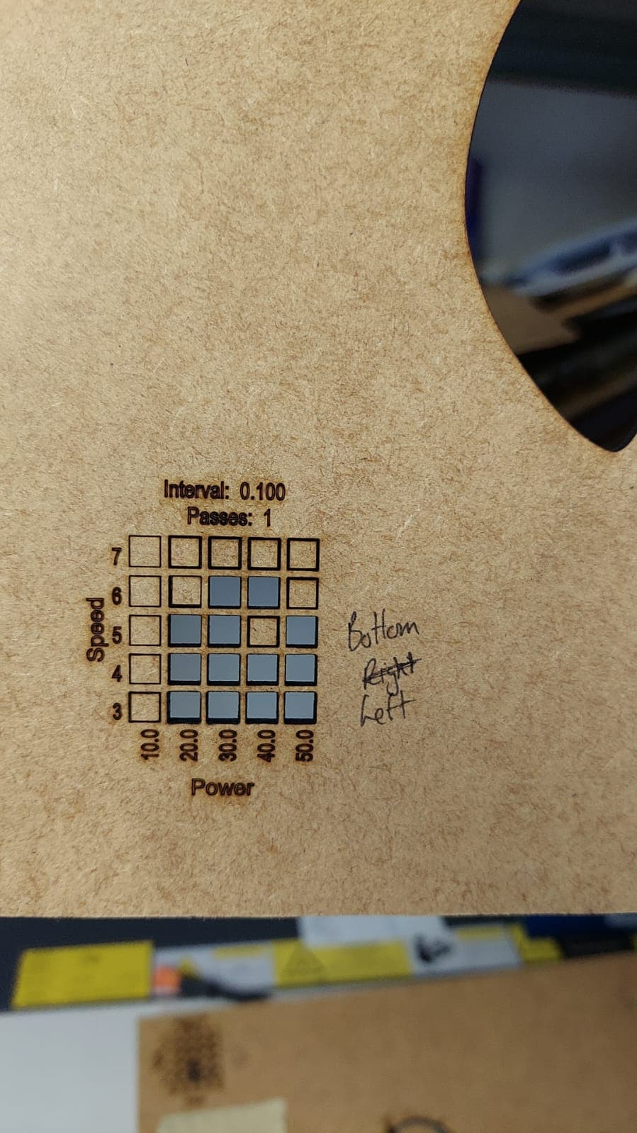
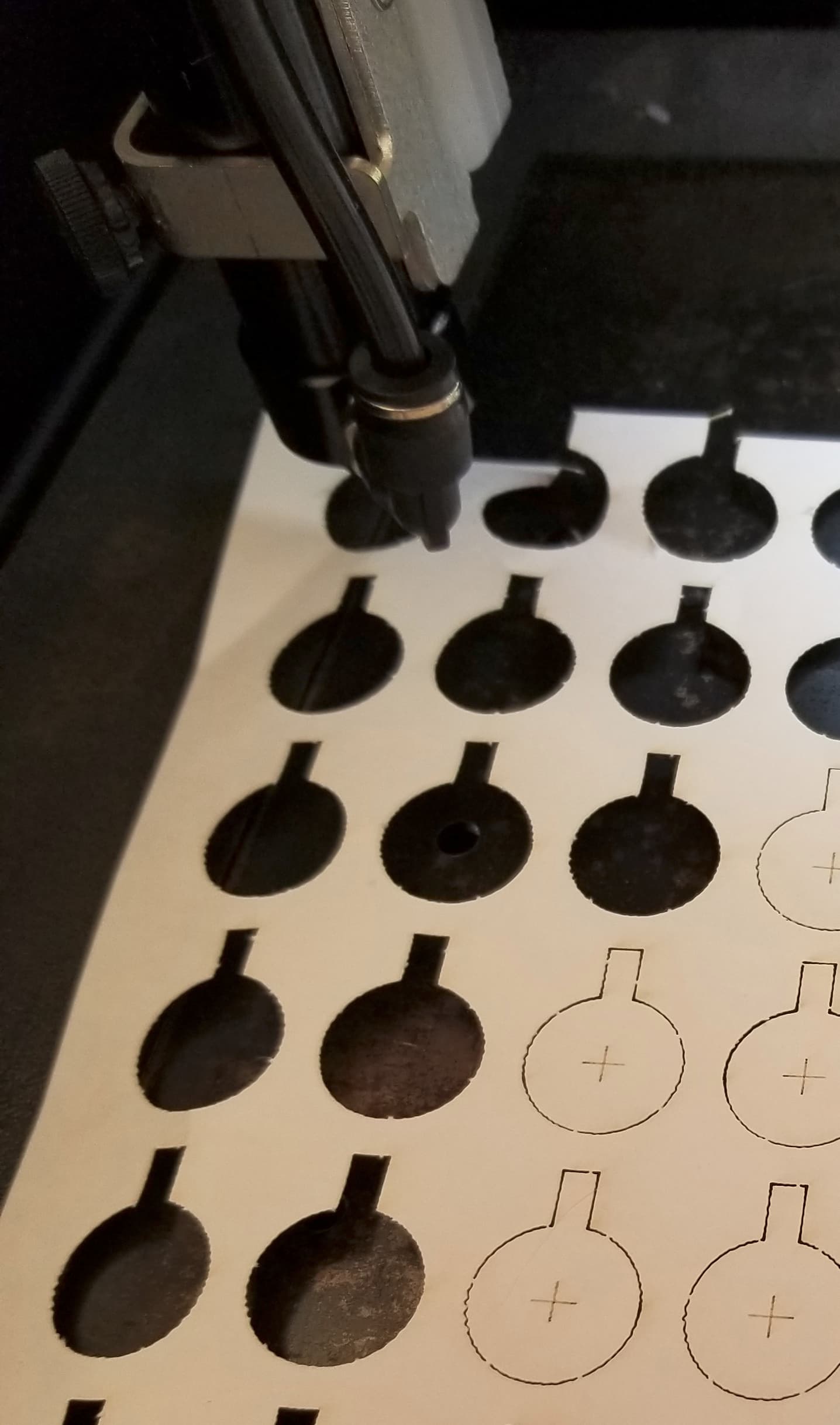
Here is the laser dont (on the tape that was placed on mirror 1) and the material tests
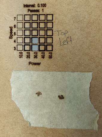
The inconsistent cutting from top to bottom indicates a beam or bed out of alignment. Am I correct?
The laser always being cooled and at 16mA or below and 315 hours indicates the tube is likely fine.
Peter, picture with your test shots of the tube doesn’t look too good.
Can’t you try to adjust your pulse duration and power in the Ruida controller so that the test puls is just exactly round? It is often very difficult to judge a CO2 tube with a pulse in the very bottom power and pulse areas.
If the tube is broken, you will easily be able to see it, as @jkwilborn points out in his comment.
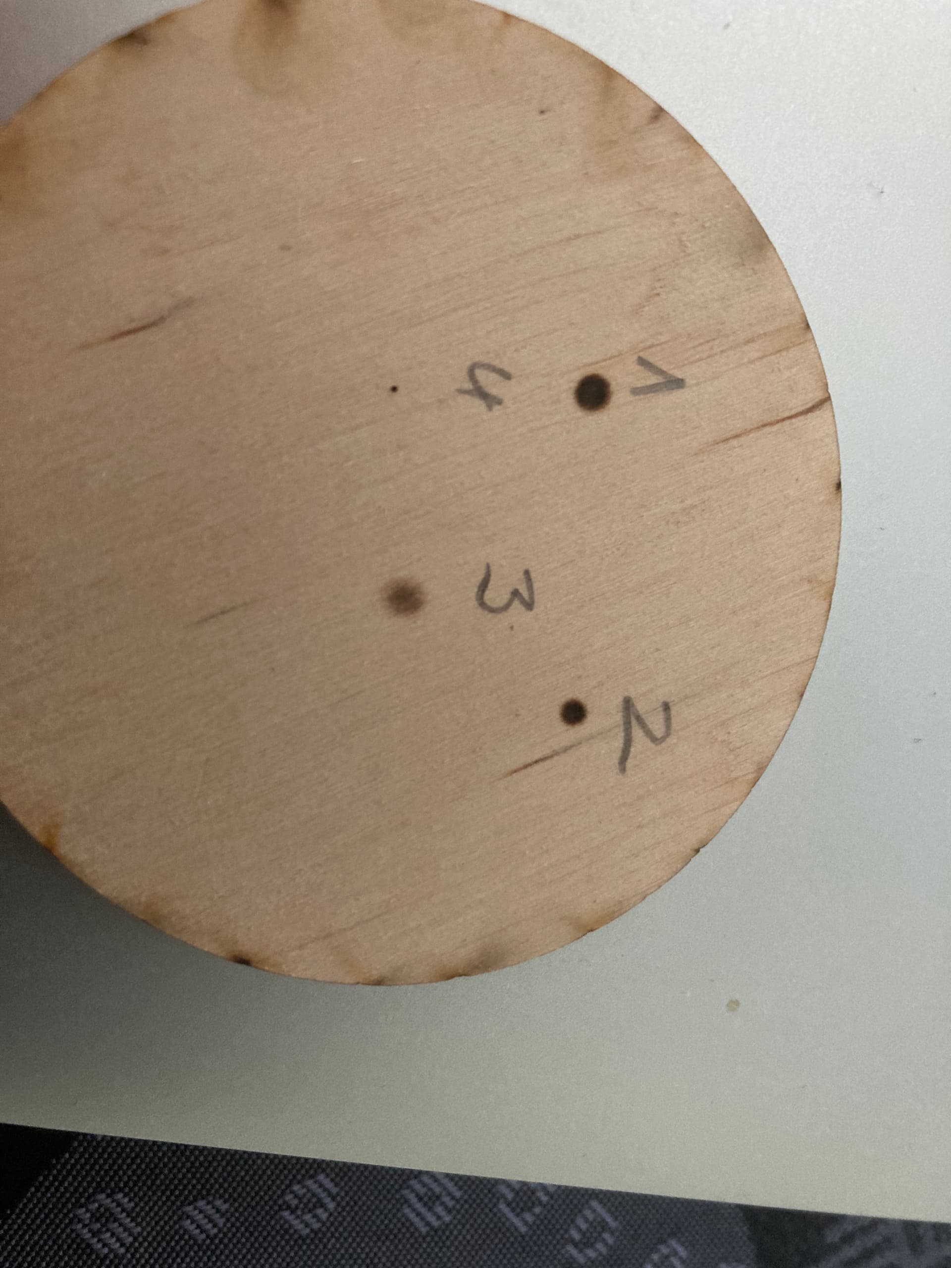
I just did a test with my 60W tube, 7 ms pulse with 11% power (Ruida settings!).
No. 1 is about 2mm, no. 2 is 1.5mm, no. 3 has lost some energy on its way to the farthest from the tube and no. 4 is through the lens and nozzle, diameter is 0.0??? and has penetrated the 3mm BB plywood disc.
That should give you an idea of how it should look roughly.
I hope your tube is not broken.
Firstly I would like to thank both Jack and Bernd for taking the time to reply so informatively on this topic - your assistance is greatly valued.
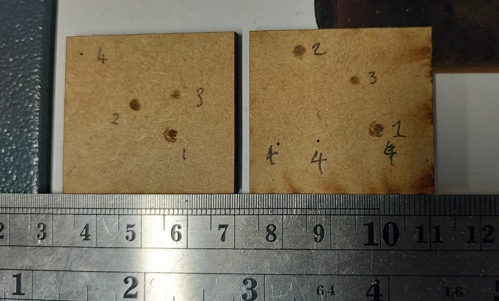
@bernd.dk : As for the test shots - the tape was placed over mirror 1 and is therefore at a 45 degree angle to the laser and appears elongated. Please see the attached images with 50ms pulse 50% power in the Ruida settings using the ‘pulse’ key on the controller front.
I labelled them 1-3 for the respective mirror position and the work was held perpendicular to the beam to prevent elongation. Hopefully these are more informative. Note nr 1 was after the first mirror not directly in front of the tube.
This image clearly shows the bean right out of the laser is not perfectly circular:
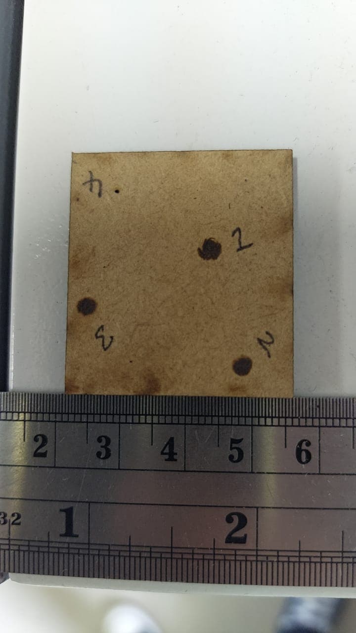
The second picture shows 100ms 50% with the same method:
=============================
I can no longer create replies to this thread, only in 6 hours time for some reason(!?)
@kst Yes the ammeter was removed already; the pulse test and ramp test were done without the ammeter
@bernd Your laser is 60W, mine is 50W so that may account for some of the difference but not all of it. My dot nr. 1 is clearly not a clean dot but more like a dot and halo - could this be because of a failing tube?
Generally, how can I determine if this is a tube or a PSU issue?
=========================
So I am going ahead and purchasing a replacement tube. It’s an expensive measure but I have a backlog of work that needs to be completed soon. I am not sure how else to solve this issue after 3 days of frustrating attempts.
Thank you, you are welcome.
I am concerned about your parameters. If you compare them to mine, your power setting is way too high and pulse time too.
Just to ask the obvious - did you try to remove the ammeter again?
It is probably connected to the fact that you are fairly new here and an automatic system tries to prevent spamming and other attacks on the forum.
Often the LightBurn people see it and manually remove the restrictions.
Even though ‘elongated’ it’s pretty clear you are not resonating in TEM0 state and therefore your tube is toast… sorry about that … it’s something you can’t fix, only replace. It is, after all, a consumable.

Appears to be a variation of TEM11

I also set the pulse to 10mS and the power to about 20%, you can pulse it multiple times if you need to. You don’t want any of the area burnt. The idea is to see the ‘power’ across the beam… or the ‘Gaussian power distribution’.
I use watercolor paper to cut out ‘targets’ that fit in the ‘hole’ … no sticky residue. it keeps the ‘debris’ from the burn off the mirror… mostly.
This is actually m2, on the gantry, but it’s the same for m1.
Wish I thought different for some reason, but I think your shot is conclusive that your tube has ‘expired’.
Maybe @JohnJohn can give you more authority to post… ![]()
Good luck
![]()
So I discussed extensively with a local laser company and they agree that it is the tube that is toast - looking especially at the spot size as @jkwilborn mentioned.
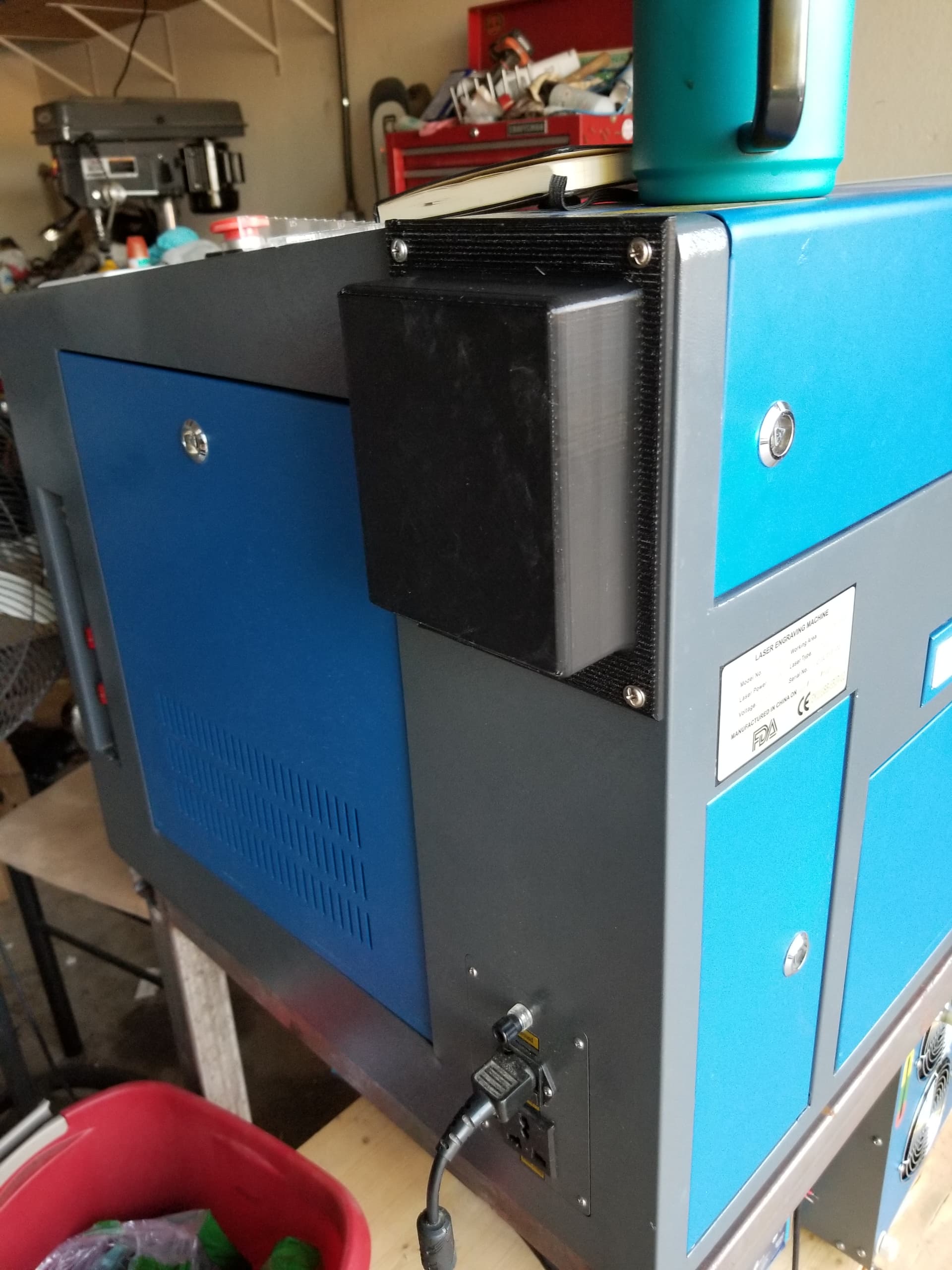
So I bought a new 50W tube and am in the process of installing it. The problem is that it is much longer than the old tube - some 20cm longer.
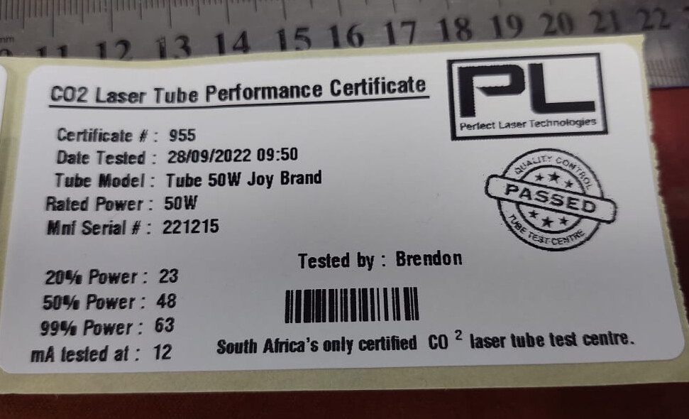
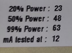
It is a Joy brand tube, the Chinese sticker is rated at 60W but the local vendor has a certified test facility where they test the tubes, for your interest I have attached the ratings card below:
They tested the tube at 12mA and it produced the output listed above that in watts at the specified duty cycle (I assume that is the duty cycle). I assume that is the percentage that I should set in Ruida as the maximum percentage. Will keep the ammeter in the loop just in case.
They lost me here… maybe you can explain
Is this output in watts, 20% gives you 23W or 23mA? What test was done at 12mA? Maybe it’s how they measured the ‘on’ time?
I assume it’s the same diameter, just longer? How long?
I had to make an ‘extension’ for mine when I changes out the tube holder…
Probably making it more complicated than need be… ![]()
The only proper way to set a current limit is via the lps internal current setting.
You need to know maximum current that you want to use for your tube, did anyone advise you of that from the testing people?
![]()
My understanding is as follows:
At 25% ‘power’ (duty cycle?) and 12mA = tube produced 23W
50% ‘power’ = the tube produced 48W
99% ‘power’ = 63W
When you say ‘on time’ do you mean duty cycle?
It is longer by 20cm, diameter is the same. I am designing a housing to protect the side.
“lps internal current setting.” - how is this achieved
They recommended no higher than 16mA
My understanding of laser power output is that it is directly correlated with input current. So a higher current = more output power = shorter tube life.
I asked them what the power level on the rating card meant and they explained it was the number on the digital readout on the test machine they use to rate the tubes. How that corresponds to a % number in lightburn or a % number in the Ruida panel is lost on me.
=============
EDIT:
Reading up a bit on this forum I have come to this understanding:
The LPS has a setting that controls the base power level. Say that is 16mA. When the LPS is on, it is supplying 16mA max.
The controller reads the Lightburn setting of 75% power for a line. So it supplies a PWM signal with a duty cycle of 75% to the LPS. The LPS switches on an off so that it is on 75% of the time and off 25% of the time. Therefore the current to the tube is 0.75 * 16 = 12mA
So then as you say, the LPS internal current setting should be set to the maximum recommended by the manufacturer (in my case 12mA per the rating card which the tube was tested at) and the desired power % for a given line can be set in Lightburn. Setting it to 25% power will produce a 23W laser beam. 50% power will produce a 48W laser beam (per the rating card)
===============
EDIT 2:
I have seen online LPS that have an adjustment pot. Mine does not. So there is no way to adjust the internal current setting. I suppose that means that I will revert to the old method of keeping an mA meter inline with the negative laser wire and ensuring the max safe current is not exceeded.
I think you don’t understand how a meter works… lets start with a regular voltmeter, like a dvm. We will measure the pwm to ensure it’s varying properly for a certain percentage.
It is easy to do… assume a 5V ttl compatible signal. I set it for 50% duty cycle.
You should read about 2.5V on the meter. You know the signal changes from 0 to 5V, yet you only read 2.5V. The meter reads the rms value of the signal. If you set it for 20%, you will read 1V, but the voltage on the signal is still going from 0 to 5V, just for 20% (or 1/5th) of the time. The same thing happens with your mA meter.
If this is true then the actual current reading is 4 times the display. Since it’s only on for 1/4 of the time.
In this is the case, when it’s ‘on’ it’s drawing 48mA… since it’s only a 25% pwm you are reading 25% of the actual current.
So you can see why I was confused from the supplied data … ![]()
Probably has an explanation, I just don’t know what it is…
So it depends on the type of meter and why we generally use a scope to see what’s happening. A current probe on the machine will show the same current every time it lases no matter the pwm. Some machines have digital meters but for humans it has to be stabilized so it gives you conflicting results.
Laser tubes, like tunnel diodes are ‘negative resistance’ devices, so Ohms law doesn’t apply… an increase in voltage doesn’t necessarily correspond to an increase in current and vice versa. You can find graphs of power output/input around the web.
Generally speaking we have more power with higher current levels… but there is no direct correlation.
Mine requires a contortionist to adjust… it’s up within the lps about an inch or more.
IMHO, I’d ensure you don’t have one, then change out the lps for one that does. Lots of people here claim they cannot adjust theirs either… so it’s a personal choice at that point…
My machine came with a test tag stating a current limit of 21mA. I set my lps to 10.5mA at 50% pwm. When it does lase, it can only draw 21mA. It will lase every time at 21mA ‘on’ and my lightburn scale goes from 0 to 100% properly. I commonly don’t need to run much higher than 80% which is about 16.5mA. I have run 85% which is about 18mA.
Good luck…
Let us know how the tube replacement works out…
![]()
So what is the problem with putting an ammeter in series with the tube on the negative side and using that to measure tube current? I have a 4-20mA meter that I use in that manner. Or does this only show RMS current?
The meter does show a different current depending on the ‘power’ setting in both the Ruida controller and Lightburn.
The replacement tube is fitted and I am doing alignment / focusing now.
The mA meter goes between the cathode (negative) end of the tube and ground. So that is correct…
Maybe I don’t understand the question or I confused you previously?
![]()
I am using a mA meter on the negative lead. If I set the power in Lightburn to 50%, I get 16mA on the meter. If I set it to 25%, I get around 10mA. So a power level in Lightburn of 50% represents the highest that I can drive the laser without damage (though in practise I will use say 14mA or 12mA for some headroom).
The above scenario applied to my previous tube. Now that it is dead, I need to know if it was because of the method that I used to manage the current. Maybe this was not the right thing to do and led to damage due to overdriving the tube. I think I doubt this as there was no decrease over 310 hours in cutting power until say 3 days ago when it dropped off sharply, but am very open to correction.
===========
I have the new tube installed, aligned and focused. At a conservative 25% power I can cut 3mm mdf at 12mm/s, which is shocking considering I was cutting it on the previous tube at 5mm/s at 50% even on the day I got the machine.
I dropped the ammeter (don’t ask) and will have to get a new one in the morning. Then a quick call to PerfectLaser should get me some info on the max current for this tube, and hopefully a more thorough explanation of the rating sticker that they filled in. Will update here when I get a better explanation from them.
When I talk about maximum current draw I’m speaking when the tube lases during it’s on time. The pwm has a period (sometimes called the pwm base frequency) and is usually expressed in seconds… a period of 1mS is 1s/1000 or 1mS. You can set the Ruida pwm period. It’s usually 50uS (20kHz).
I think you missed what I was saying. When your tube lases, it lases at 100% power for 50% of the time, a 50% pwm cycle. Your meter reads 16mA or 1/2 the total current. For a 50% pwm reading of 16mA, it has to be drawing 32mA during it’s ‘on’ time.
Changing pwm percentage does not change how much current it draws when it lases… only the lps can control that. It affects what you read off the meter only… however, it’s the only real indicator we have available.
Does that make sense?
Did you take the time and really look over the lps for a current adjustment?
Bummer… could have been worse…like dropping the ‘new’ tube…![]()
I think you ran this rather warm, if I recall and I’d attribute it to that above anything else. Of course it all adds up…
If it were me, I’d change out the lps for one that I could control the current…
What kind of current are you reading at 50% with your new tube?
Whatever it is, multiply it by 2 for the actual current.
![]()
Truly, the darkest art is the art of laser mirror alignment. ![]()
Surely the current the tube is seeing is the same as what the ammeter is seeing? That is, the RMS current?
Either way, the laser supplier recommends no greater than 12mA on the meter - seems high for a 50W tube so I will de-rate that a bit too.
I found it hard to get a good explanation of the rating card. But I have a friend coming over with a scope to check the lps output and will adjust accordingly. The new ammeter is arriving Monday
============
In the meantime I have been cutting - the tube just just ignites at 13% (Lightburn) power and cuts 3mm MDF comfortably at 8mm/s 18% so for now I am going no higher until I can confirm the amperage. Maybe this is risky but I have a very urgent cutting job that needs to be done, so I am taking a calculated risk.
Experiencing a brand new tube makes me really think I was taken for a ride previously (the seller promised the tube was new and was treated well, and I believed him because he seemed honest). The beam quality is night and day. The kerf width is practically nothing compared to the previous tube.
I will continue to update this thread as I progress, until I have gotten stable operating parameters dialled in.
===========
My controller is a Ruida 6445G and I am trying to decipher the poor English to find out how to reset the tube life counter.
My tube is 880mm in length… it is rated at 50W but reads 44W with a Mahoney power meter and with the doHICky (~30 min video) by Sadler…
The max current rating on my tube is 21mA… almost twice what you have as a maximum. I don’t have a problem cutting at 18mA and have been. So I’m wondering if you have the correct maximum or someones interpretation of what a safe maximum is… Seems awfully low to me… the manufacturer would/should know.
I try to set mine up with what makes me comfortable… 90% or more of the people using these are totally ignoring many of these ‘conservative’ steps such as a very low mA. Many run for a long time, so don’t worry yourself too much about losing a tube. If you use it, it will get ‘dull’ just like a knife, the difference is a tube will get ‘dull’ just sitting there with non-use…
If you need to use it, I’d say use it…
The most simple way to set the lps current is with an installed mA meter.
If you don’t have a mA meter installed, then you need something to measure current with… a current probe for a scope is usually pretty expensive.
I measure it with the scope across the mA meter, but it needs to be installed…
Good luck …
How long is your tube ?
![]()
My tube is 1020mm long but my lps is either underrated for the current tube or overrated for the old tube (more likely).
Will report back when my friend brings his scope.