I installed a second 24V power supply in my 60W OMTECH laser. I did this to take the load of the 24V accessories off the OEM power supply. I have extra lighting, air assist solenoids and the relays that control them. This is where the issue is occurring. The dual relay I’m using are set up for active low control, status will trigger one of the relays to turn on the low pressure solenoid and wind will turn on the other. The problem is the ground for the KT332N is not the same ground as the new power supply. Chassis ground and 24V electronics ground are the same on the OEM power supply, not so on the second one. Can I safely connect the 24V grounds of both power supplies together, so that I will have one common ground? The AC input on both share the same ground.
Only grounds you wouldn’t tie together would be floating grounds inside the power supply. All others are good to go.
The one thing I did notice is that the ground for the 5V portion of the supply was not tied to the chassis or 24V ground. What concerned me was that the 24V ground on the new supply wasn’t wired to the supplies metal chassis. I’ll start out with the two 24V grounds jumpered together and see how that works. Thanks for your input.
I’m sure outsides are all grounded. You can check with multimeter.
The chassis and 24V ground are at the same potential (it’s the first thing I checked with my VOM) on the OEM power supply, but that’s not the case with the new one. I ran a quick and everything seems to be working correctly, so I’ll just keep an eye on it for a bit.
I picked up a supply from Amazon and sizzled a board. I measured between common on the new supply and ground… There was a 40V difference… hence I lost a controller…
Now, I always check these… supplies from China are a crap shoot, so check them before using them…
Cheap insurance.
![]()
Hi Paul,
There’s no issue connecting the negatives of the supplies to a common or ground. You can make sure the secondary voltages are matching when under a load just to ensure there’s not going to be any issues with the internal circuit protection on the controller.
I would’ve been perfectly happy to leave them isolated from each other, except that I was using “status” and “wind” from the controller to trigger the air assist relays. That necessitated a common ground. With just the grounds tied together it looks like I’m good to go.
I struggled with using the onboard Air assist an Fan terminals to power an outside powered air assist and an exhaust fan. Tried solid state relays. Could not get enough to trigger the SSR (3-32v), ended up with omtech recommended relays. Sounds similar to yours. don’t quite understand the hi/lo setting. The two relays did not react to signals the same.
Did you read my previous post… I think that’s kind of a dangerous blanket statement for any novice to read.
On a Ruida the solenoids are wired to 24V, then the Ruida completes the ground or sinks current for the selected solenoid(s)… so I guess I’m not following what grounds you tied together…
![]()
Running multiple matching supplies in parallel isn’t a problem as long as the voltages are matching and you don’t exceed the current rating of the controller’s output relays.
edit: matching supply means same voltage & current. Ideally you want them to be the same brand & model number.
In the real world, even the same brand and model may be off each other by a tenth or hundredth of a volt, at that point they are fighting each other…
Running a common grounds from different supplies that operate other equipment is fine, but you should not parallel power supplies…
This was my training in industry and never saw it done there… without some type of balancing resistors/network between them.
If you can enlighten me, I’m all for it…
![]()
I’m hoping this picture will help clear up some of the confusion I’ve caused. My goal was to keep only the original load on the OEM power supply. Because I was adding extra power requirements to the laser I added a second 24V supply. The issue I had was that using the “wind” and “status” signals to trigger the relays required a common ground so that the relays circuitry could respond to the low that the controller was providing. The relay wasn’t reacting to wind and status before I tied the grounds together, but it is working correctly now. I think part of the problem was that on the OEM supply, the case and -24 were the same (I checked it with a VOM). On the new supply they were not. The grounds are common, the +24V are not. The relays are providing a ground to the solenoids in keeping with the same control philosophy, in that wind and status provide a current sink.
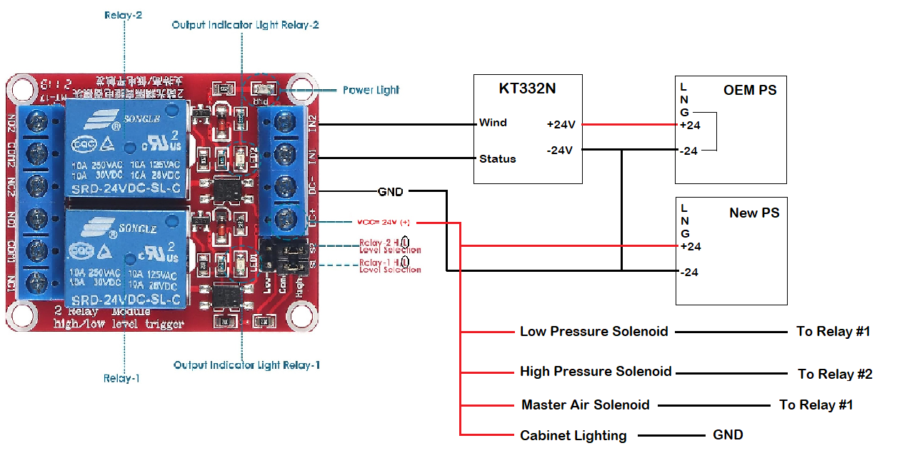
From your schematic, it’s likely the G on the lower power supply is actually cabinet ground, whereas the -24 could, optionally be at ground… Might want to measure with power on, if there is a difference between G and -24V. You might be able to tie them together.
The most simple is wire the new supply to the -24V to common ground and the positive to each solenoid. Let the Ruida pull it to ground.
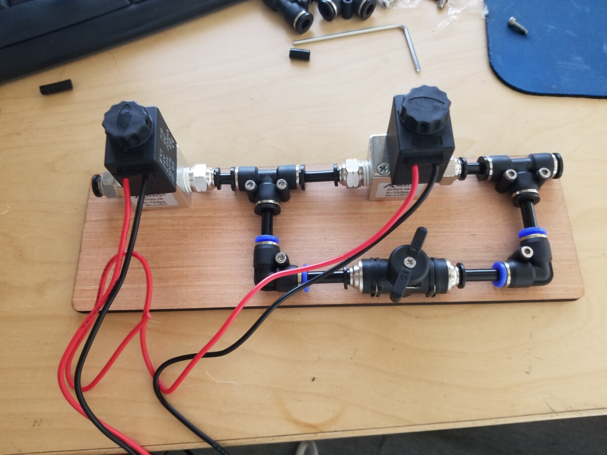
I wired mine up, but didn’t need an extra supply or three solenoids… Left one picks when status goes low, supplies low pressure air… the right one via wind, bypasses the restriction to allow full pressure air…
Sorry, suspicious when you use the same signal to pick two different solenoids on the same air circuit… especially with this configuration. If there is reason like a regulator or something… let us know, one more item to the bag of tricks…
Did you really need to upgrade or add another supply?
Was there that much of a load added? My solenoids draw ~160mA each.
Just curious…
![]()
The master air solenoid comes on with status so that I don’t have air pressure on the downstream equipment (regulator, solenoids) unless I’m lasing, and I had a bunch of extra relays, so I thought I’d use them. “Status” and “wind” only trigger the relay, the relay then controls the solenoids. This way the relays and the solenoids are isolated from the controller. I’ve added a LOT of extra lighting and a fan bank to blow air across my cutting boards while I’m engraving them, the second PS was inexpensive, so I decided to put everything that wasn’t originally connected to the OEM PS onto a second one. I’d considered tying the case and -24 together on the new PS, but not knowing how it’s wired internally I felt that tying the -24 contacts together was the safer option.
Thanks, but, too low of a level of details here, I’m talking about, simply when status goes low the solenoid is eventually activated, no relays or 20 relays…
Anytime the machine is executing a layer, status is low. The machine has to be executing a layer. I use this, via restriction. Using low pressure the main purpose is keep debris off the lens anytime it’s executing.
Wind is only active when it’s executing a layer and air assist on that layer is active.
You have two solenoids driven off Status, is it how it’s plumbed?
We can drop it… sometimes I’m too curious for others…
![]()
Jack, I find your input extremely valuable. I’m basically using your setup (the fittings are arraigned a bit differently), but for air assist I just wanted the KT332N only for control and pushed the power requirements elsewhere. I guess this falls under the heading of “more than one way to skin a cat”. It does exactly what I expect it to do (now), so I’m happy.
Looks good!
Having a single connection from the power supply - terminals to the power line G terminal is correct:
- It ensures the entire electronics layout is connected to frame / safety ground
- It eliminates the possibility of a “ground loop” current circulating through the supplies and the frame
In general, the wiring connected to frame ground (and, thus, the AC line’s yellow/green earth ground wire) would be the circuit “common” node, with all voltages measured relative to it.
The - terminal on the supply should be isolated from its own frame and G terminal, so that you could use the supply for either polarity:
- +24 V by connecting
-to common - -24 V by connecting
+to common
Bonus: you may find the OEM supply is underpowered for the loads it must carry. The supply in my laser is definitely overloaded (but coping) and a recent thread suggests that situation is common.
Which is why I added a 24 V laptop brick for the LEDs and solenoids and suchlike. The OEM supply is still overloaded, but at least I haven’t added to its misery. ![]()
The new power supply is wired this way, the OEM power supply is not. The AC earth ground, the case and the -24 are all the same on the OEM supply (measured with a VOM).
If that’s with the jumper from - to G removed, then I’d say it’s unusual enough to come as a surprise.
Which is why I tend to do exactly as you have: measure resistances from here to there, even when I’m pretty sure I know the answer.
Sometimes, I’m surprised. ![]()