Read the instructions and watched the LE video, but split size still does not make sense. LE used a factor of 2,4,or so on their engrave which made it fairly small.
I have a file that if I go small I get bascially non functioning output (I have opened a ticket with LB and sent them the file)>
I am black annealing on a SS304 tumbler. It needs a small LPI of .005, so I thought I needed a split size in .02 or so. This causes 2000+ slices which is a problem with actually doing the work.
For a high lpi anneal what would be a good split size?
Hey G’day, I have spent several days on this, I sent in a ticket several days ago to support still no reply.
I have got my galvo working ok with rotary with the following process, 1. fill shapes individually. 2. set split size to 2x or 3x your line width. This gives you the quickest rotary operation with Galvo and do do a full jacket around a bottle is 10 to 15 minutes depending on the design.
If you have any large areas to do it becomes a nightmare especially if you don’t use fill shapes individually.
My personal belief how they have set rotary to work with Galvo is flawed.
First you can’t get continuous rotary motion, you can with a diode laser running a cheap board, co2 so I don’t know if its a limitation with the ezcad board or what. No direct answers from digging in the forums.
The way you have to set up the stepper is so wrong 12800 rotations for 360 turn? Again is this a limitation of ezcad boards or what?
If your work is centred and and rotary centred as far as the machinery is concerned its a flat working area so why the limitation and split sizes? If anyone can explain why this coded for galvo rotary I could stop moaning about it and get on with the limitations at hand.
Its a little like the cleaning pass when doing 2.5d, why is it not a full clean, we don’t need whats being cut next to be clean we need the whole coin cleaned to stop the post processing or at least minimise it when the job is done.
Chuck or roller rotary?
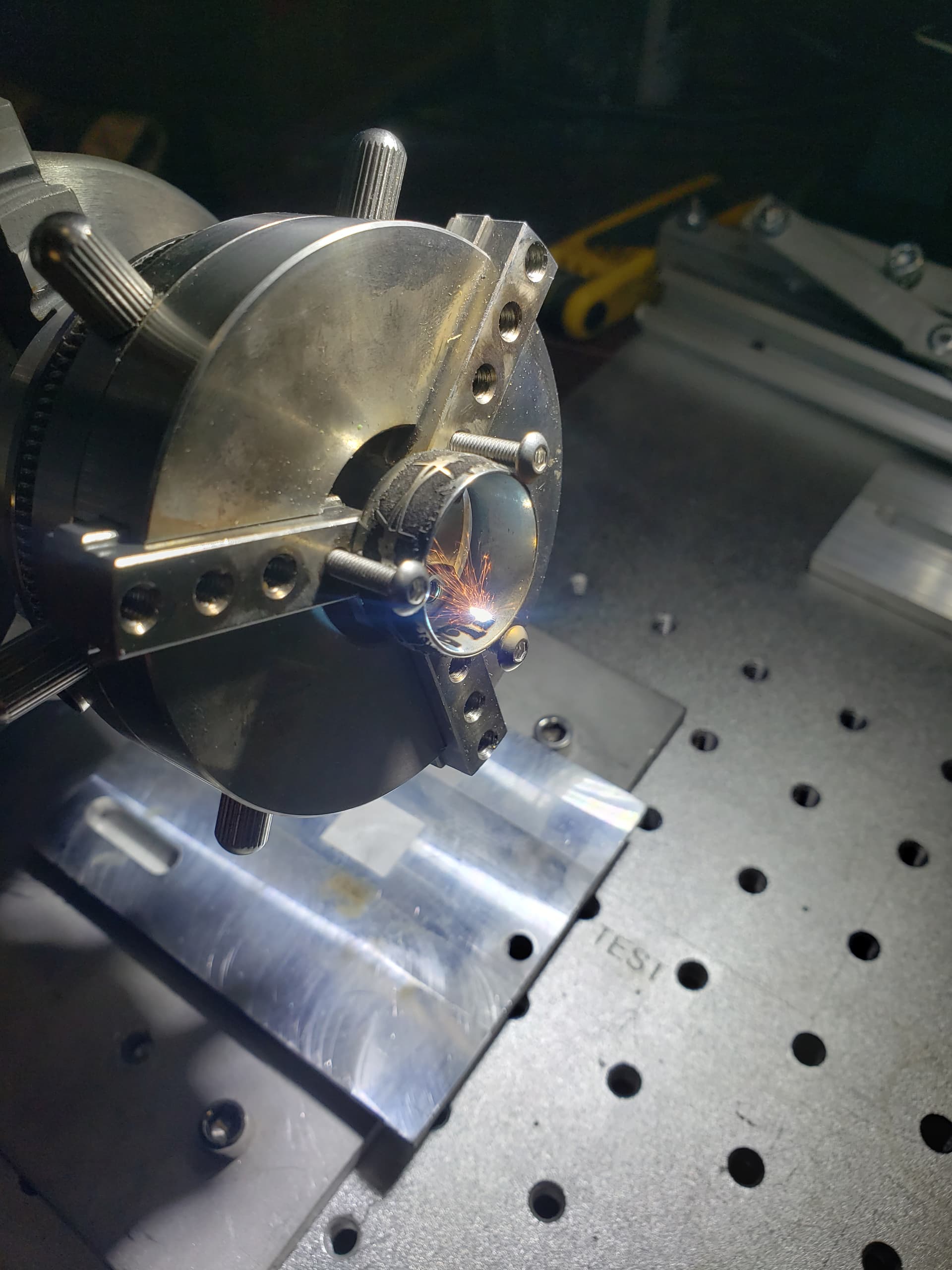
Below applies mostly to my experience with fiber laser/ chuck rotary, Yeti and similar tumblers, working with both a 6400 step set up direct drive chuck type and a 34800 step belt drive chuck type.
First, Stainless steel anneals black nicely with a large lens slightly out of focus. I use 175X175 3-5mm out or 300x300 8-10mm out. The 300x300 is the ticket but you can get good results out of the smaller ones just setup is less forgiving.
Second, you can increase the line increment to 0.01-0.025 depending on lens/ focus and formula below. Pick up a lot of time.
Third, for step/ slice/ LI, divide the circumference by the rotary steps. This will give you the actual surface distance the tumbler will move with 1 step of the rotary. Multiples of this number make a good slice, as there is no reason to tell the rotary to stop somewhere it physically can’t. That will cause a cadence that shows up in the annealing.
Then use divisor of split for line increment. The more accurately the measurement the less the need for any overlap. I have good results with zero overlap.
4th, more steps on the microstep driver = smoother rotation but less accuracy. Better to keep steps on the dip switches 5000-6400 and use mechanical means to increase steps (Belt drive reduction, zero backlash gear drive reduction) Just my opinion, probably get a cussing for that from someone around here.
5th, filling shapes individually will slow you down compared to filling all shapes in each slice, as the fiber galvo laser jumps hundreds times faster then the rotary spins.
Where individual filling can possibly speed things up with a galvo/ rotary is when you are using the “Run Whole Shapes, If Possible” setting when you have lots of small objects like text. Results will start to skew when using it on larger objects and if the larger objects are close together perpendicular to the rotary axis, margins will get smaller to the point the objects will overlap.
Agree with @grumpy22 the galvo’s BJJCZ (EZCad 2) board handles the rotary a lot differently then the other machine types controllers. I try to limit my steps to avoid maxing it’s memory by using larger slicing, get really good results 500-3000 slices. Same as individual filling, the galvo moves so much faster then the rotary, and with a tiny step the rotary never comes up to speed increasing time even more. Use as large a step as possible without skewing or degrading artwork.
A multiple of the interval seems to be the best for my use. This is related to what lens you use.
A shorter lens has less depth of field (focus) and necessitates less of a rotation for a split size… of course this is also taking into account the diameter of the object.
I’d suggest at least an 0.2mm, maybe 2.0mm for a split sized depending on object diameter.
I’m recalling this from memory, but I believe Oz stated that unlike a Ruida where all the code is stored on the controller, the rotary on a galvo is manipulated by Lightburn. When it rotates the rotary, the software has to wait for it to complete the rotary operation before moving on… this can create quite a delay with the numbers of scans that are required for most galvo jobs.
So a bigger split size should make the job run faster. This seems to work for me.
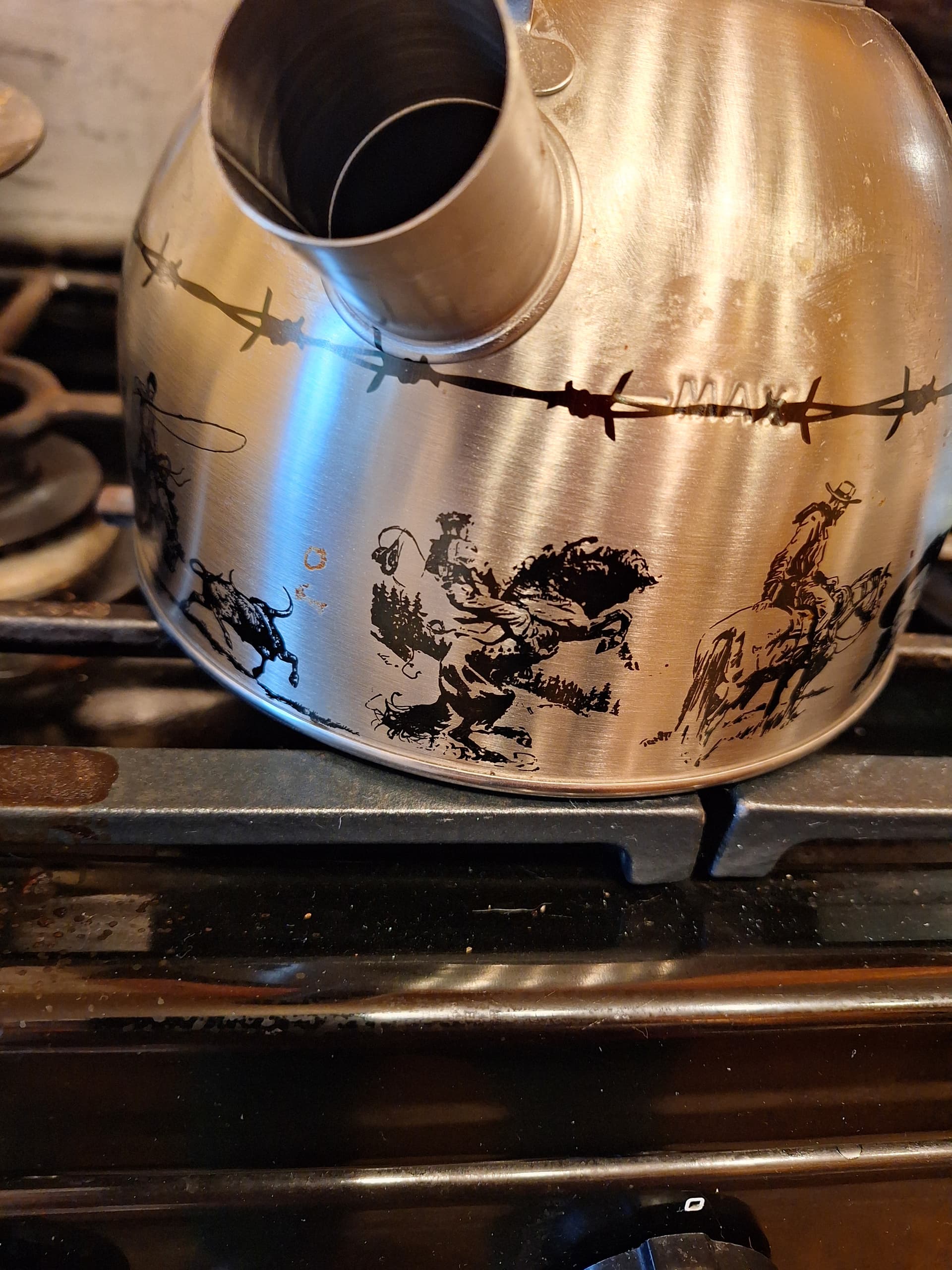
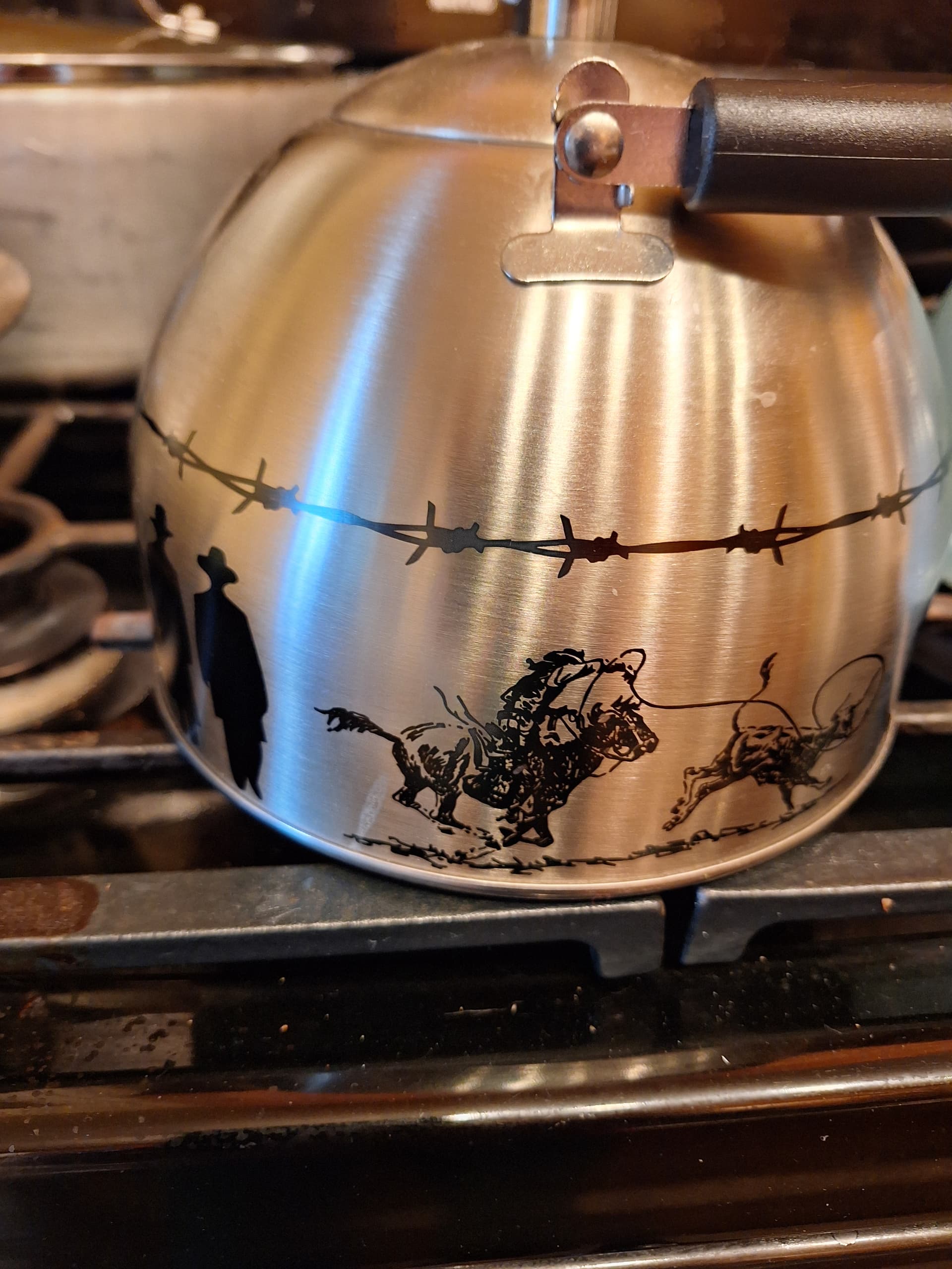
Rotary black annealing on a teapot.
Had to block up the rotary quite a bit to clear the spout, almost ran out of tower, over the 700mm mark on the 800mm tower. 300mmX300mm F=420 lens.
If it’s in the house and stainless it’s fair game for practice!
No, sorry, but it was probably 2 or 3 mm at least.
LB needs to save rotary settings with the individual files like it does with parameters, instead of globally. Think I voted on that request a while back.
Thank you all for the thoughtful comments. I’ll reference this and mess with the math on the split settings, I ahve 24-25 of these to do and at about 2 hours each on the fiber now any speed up would be fabulous.
Thank you for a very detailed break down of what you do,
if I am understanding you correctly, to determine your line width you take the circumference and divide by steps, so 223.06 / 12800 = 0.0174265625 so line width would then be 0.0175 then multiples of this for split size? 0.035 or 0.070?
I have other rotary’s set up for diode/co2/CnC the steps distance to move are calculated in a totally different way, same with the fdm printer as well.
I do not have enough room around the fibre laser to rebuild the rotary setup to a belt.
And yes you are right the more steps less accuracy less torque. If I set my CnC to 12800 steps it wouldn’t be able to cut quickly and any movement would make it skip steps.
I did read further below in the post that unlike a ruida where the whole movement is dumped to ram Lightburn has to do the calculations instead. I can understand why they do what they do now with the galvo. So information like yours is exceptionally valuable to develop a workflow that works, that is accurate and doesn’t require forever to complete.
I have learned something new today, I thank you for taking the time to add to this thread I’m sure what you have posted will help many other achieve much better outcomes with their rotary’s.
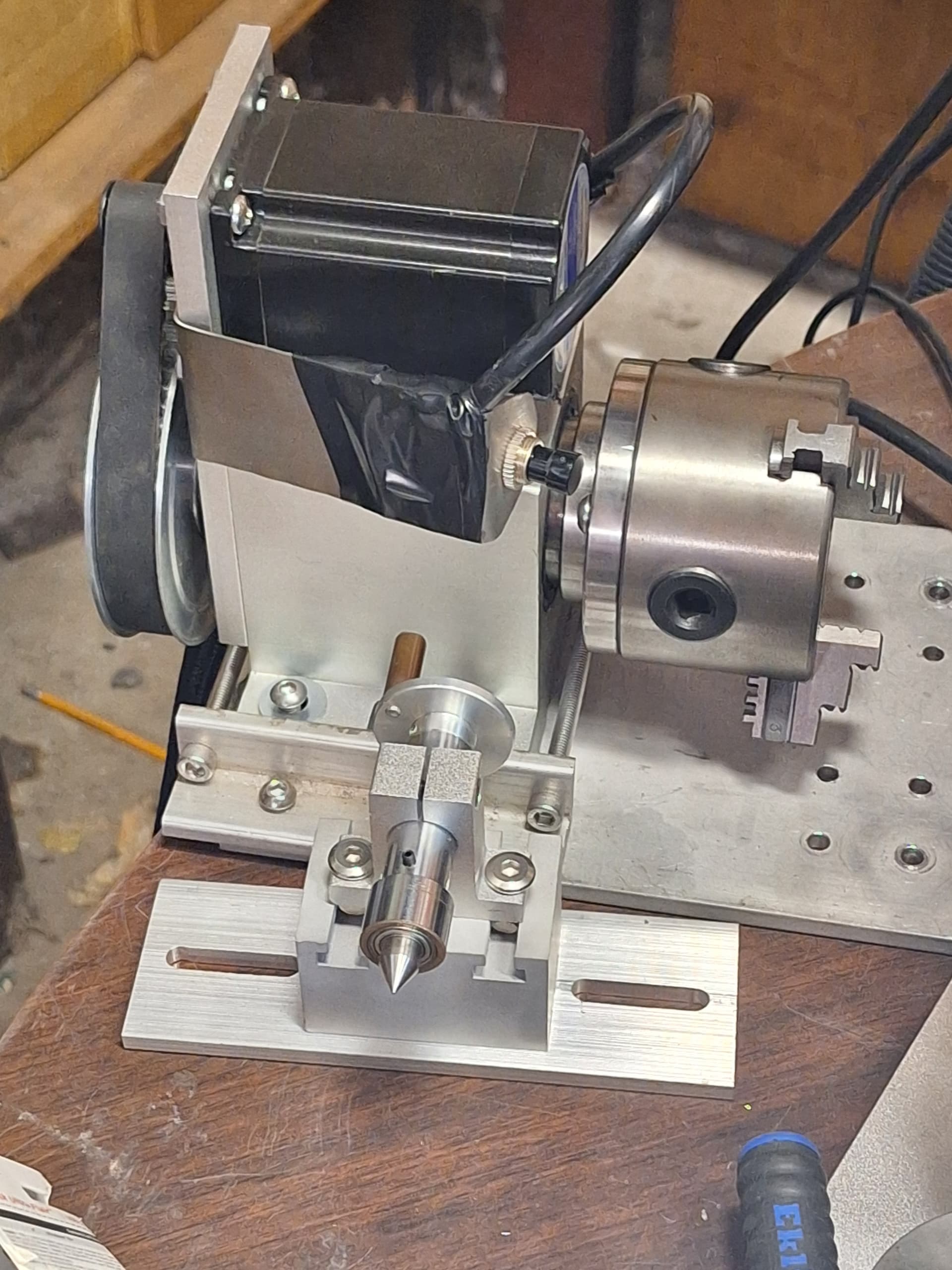
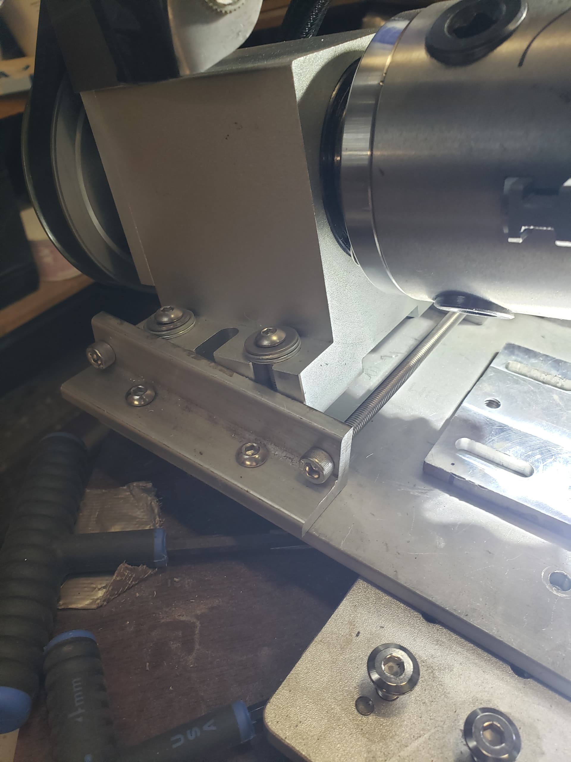
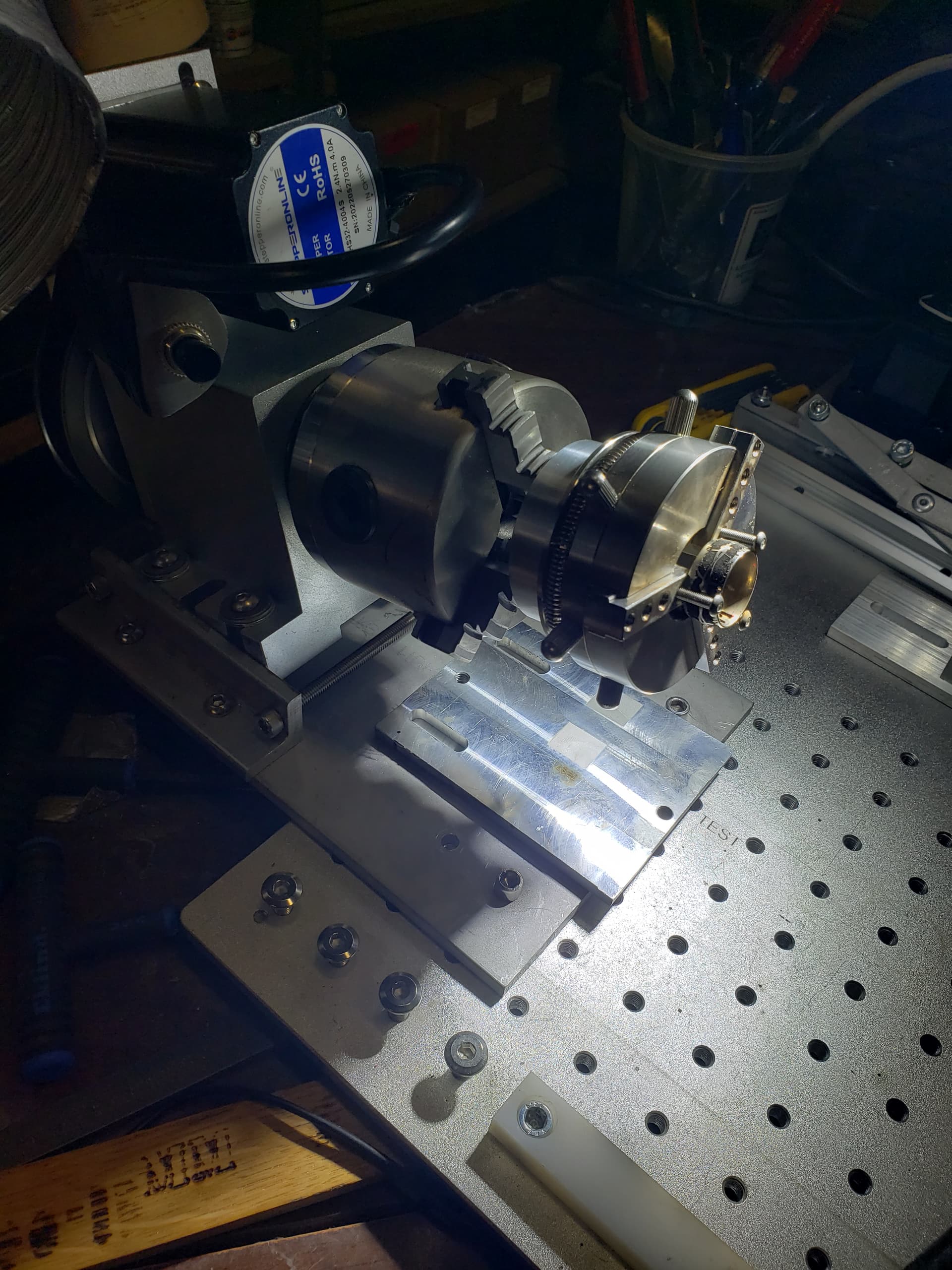
That is very compact indeed!! How do you go about the tilt? adjusting for angle say for a tapered bottle which I seem to come across all the time sigh…
I see you mention brackets for inclined position I can quite make out how that is working from the photo.
Thank you for sharing that, I have a 30:1 worm drive I could use which is very compact but I don’t think 30:1 is quite enough resolution?
This one is 6:1, my table is 10:1. 30:1 probably be way too much, but you could set the microstep to 640 or 1280 I suppose, no reason that wouldn’t work. Backlash is the key, or not having backlash.
Anyway, to tilt I loosen the screws pointing down, tilt the rotary, and tighten the side screws. Could shim but doesn’t seem necessary. Really basic, i was going to make some kind of screw jack but this works fine for inside rings and tapered tumblers. Also have a jewelry chuck, just grab it with the jaws.
Speaking of jewellery I was looking at buying one of those but one that can swivel 90deg - unfortunately the rotary I have can only do maybe 45deg if lucky. I would have to rebuild. Any recommendations?
And ty for sharing your work flow and information. It is appreciated.
If it’s in the house and stainless it’s fair game for practice!
I had to have had the best belly laugh in a long time, my wife stands at my shoulder every time I approach the cutlery drawer lol, I happened to have the same umm sense of adventure which my wife opposes very much.
Ty for sharing that and it looks great, pity I don’t have one of those in the house ours is electric, but it does have a stainless outer… hrmmm…
I think my 1:1 will tilt up 90, but if I wanted to use the 6:1 I guess I would drill and tap a piece of angle. The way it is set up now it will tilt enough for inside a ring or tapered tumblers but that’s about it. Hard to get one setup that does it all.
This discussion was helpful and I would like to thank the more technical answers.
I ened up for doing a tumbler going as high as split of 5mm, this visiably rotates the tumbler 5mm at a time, does the pass and then steps another 5mm. For something not focus critical with longer lenses (was using a 290) there was no ill effect, gaps, streaks etc, with the piburn grip.
I then was doing a glass with the Montana Gold chalk paint spray method and that I did cut it down a bit, probably not necessary as I thought I was seeing some streaking in the results, but it was just debris from the engrave on the glass itself after scrubbing it off.
If you go to small on the split size you get an enormous number of “steps” around the cylinder/tumbler/glass etc and if you are too small you can pretty much lock up lightburn as it tries to chew through a couple thousand which prompted the origina; post on this topic.
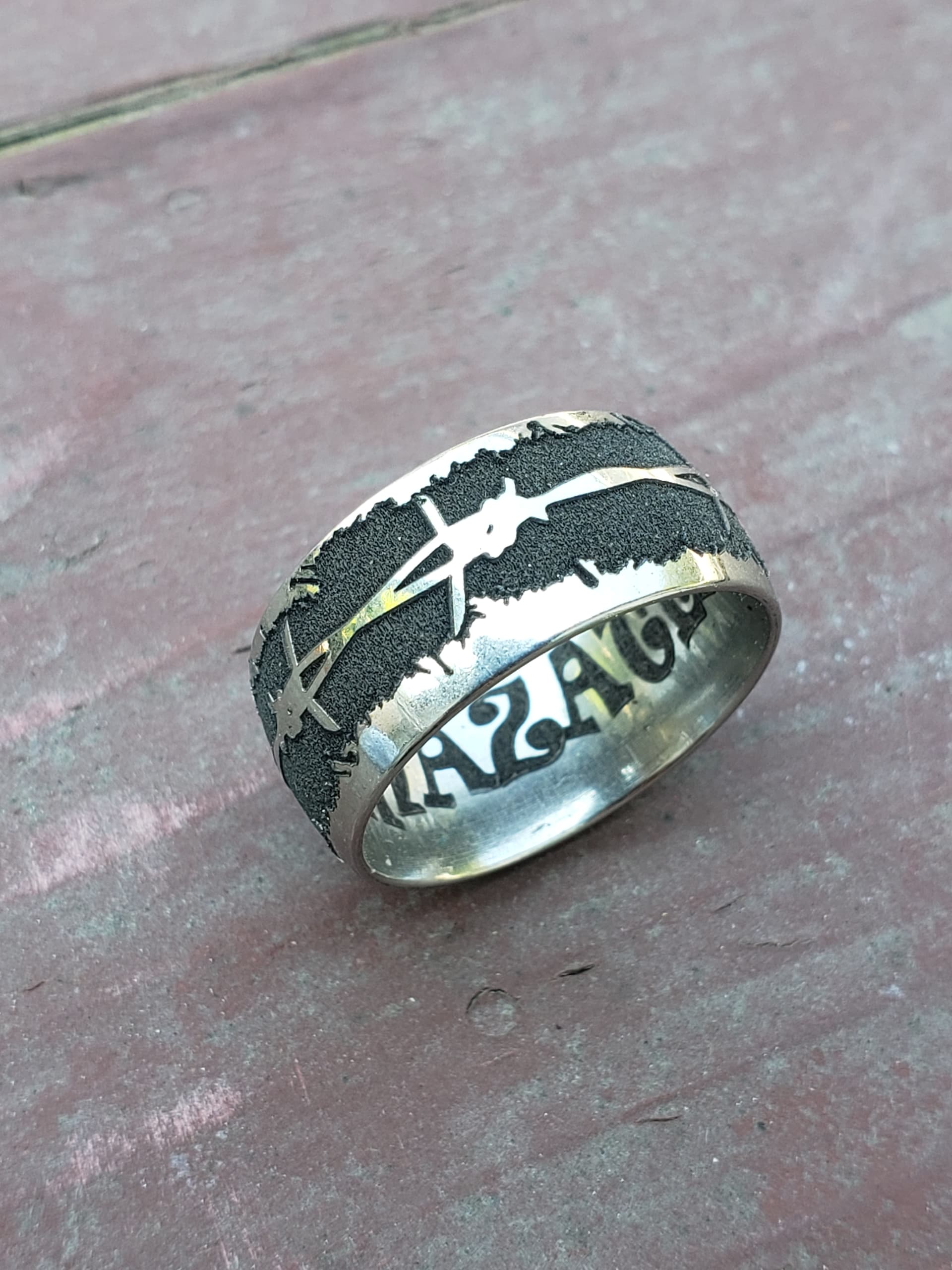
Agree, if everything else is dialed in a larger split has some advantages, big one being speed. I have also ran different splits and line intervals over the same piece for deep engraving/ multiple passes on the rotary. The ring above is an example of that.