This is both depressed
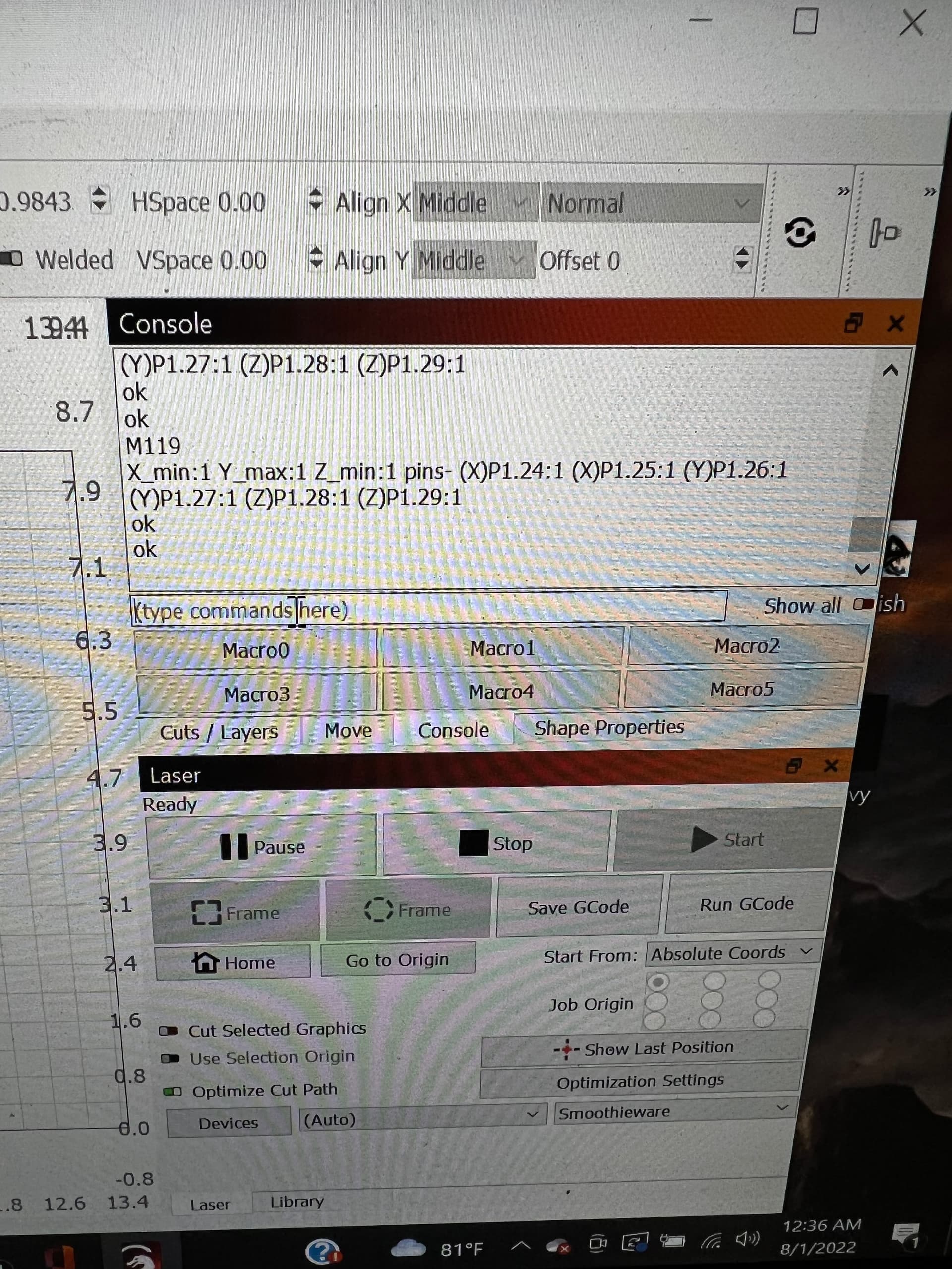
Something is definitely weird. Y seems to be toggling the status. Why it’s inverted I don’t know. Is it possible you switched the wiring on the switch? Although the fact that they’re all inverted is another matter.
X seems not to be working. Can you try swapping X and Y switches and testing again? Would like to see if the issue switches sides or remains on the same side.
With both switches activated nothing is toggled which is odd.
Everything is mounted where they came you want me to unscrew them?
I just want to mention that this machine worked until he ‘moved the head’ by hand, actual cause or not.
IMHO, none of this is going to change …
- the physical hardware switches from NO to NC or the physical wiring
- the configuration file on the SD card (I assume that’s where it lives)
My confidence is high on point 1. This has to be some kind of hardware issue. The only place it fails is during homing. Otherwise it operates properly.
The display of the limit switch status… is that relative to if it’s set to invert or not?
Is it showing a 1 because it’s active low. the pin is low or active. Or is it an actual 1 from the state from a high state of the pin…?
![]()
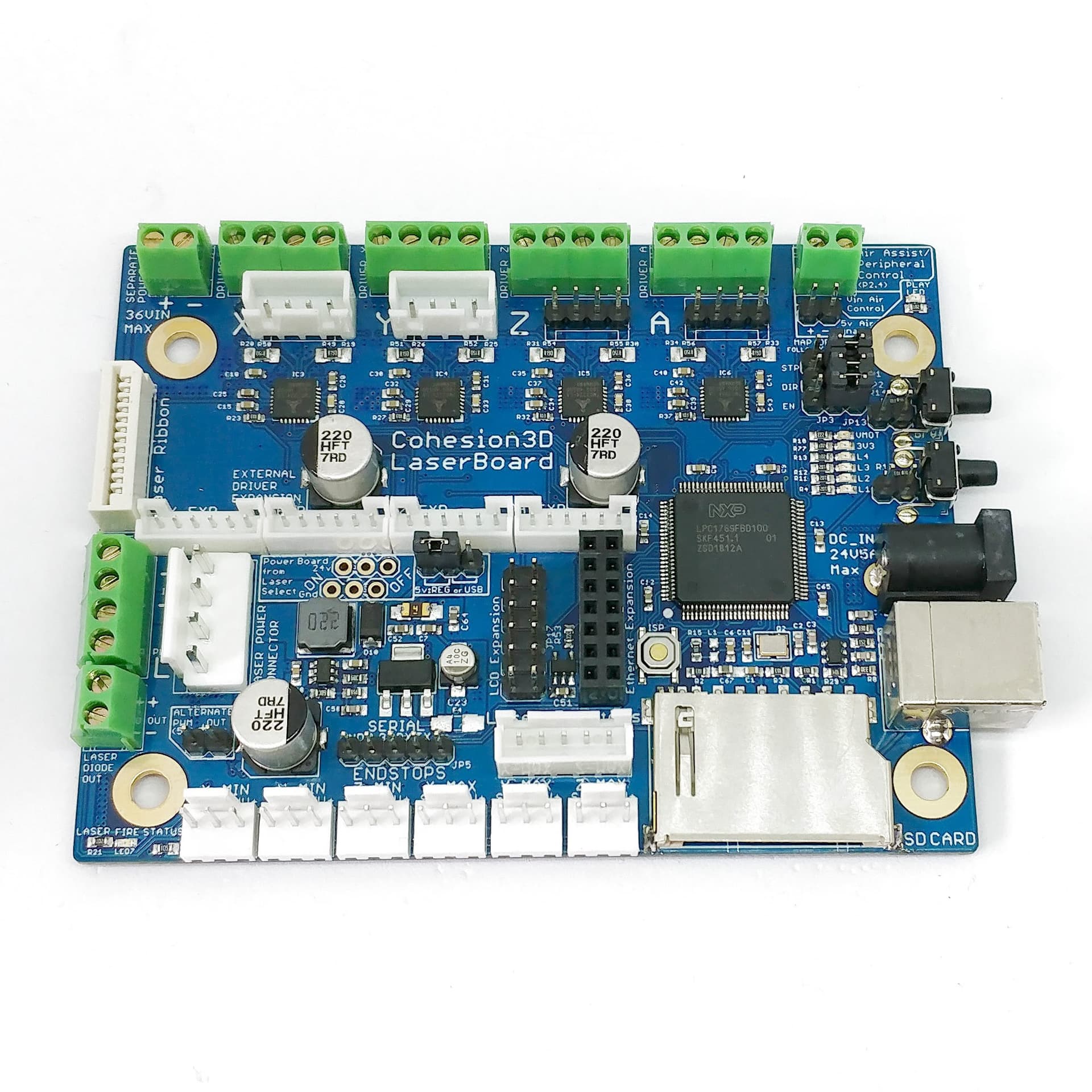
Swap at the controller.
If inverted the statuses should flip.
Status is not an absolute state. It simply means the switch is active relative to expectation.
I ordered a new board and a new limit switch. What else if anything would you like me to try?
Are you able to swap the switches and run the test again? That will determine if the issue is at the switch or elsewhere.
I guess I don’t understand, they are physical switches physically swapping them
On the frame I do t think would tell us anything as it doesn’t hit them due to it just joking in random spots.
I’m saying at the controller, swap the cables that come in from the switches.
Then run the M119 tests again for X, Y, XY combo. This will determine if the fault in behavior that we saw for X and XY combos is something south of the controller or in the controller itself. If the issue switches to Y side then that would imply something wrong with the X cable/switch combo. If it stays on the same side that implies something on the controller itself.
They are all wired into one plug soldered in
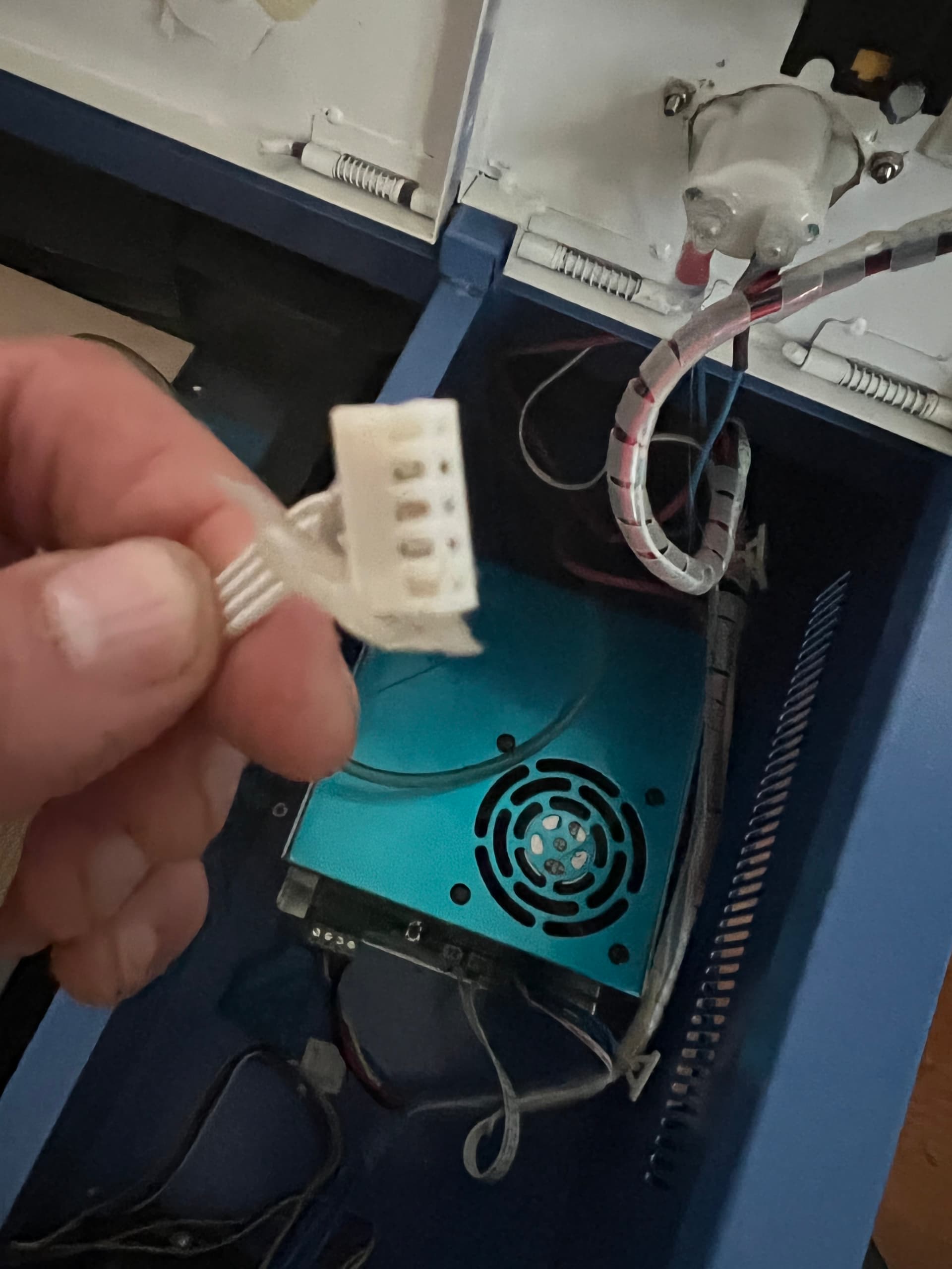
So you’re saying both limit switches are wired into that 4-wire ribbon and then the 5-pin connector spans across the X and Y ports?
Which endstop ports and pins does it span? And which pins go to what?
I don’t see how that’s supposed to work, especially given that the valid endstop according to your config should be X min and Y max.
Yes, two wires to each end stop, they all go into this one plug and plug into the board.
Can you detail out exactly what pins go where? Trace all the way from each limit switch all the way to the pin on the board.
Yes I used the continuity tester and they all get tone so don’t seem like the wire is bad.

Likely ground for the common pin but not certain.
What I’m asking you to do is to document the wiring from switches all the way to the board. Can you document the actual wiring so I can understand what’s happening? So far nothing is as anticipated so having to build up an understanding from scratch.
![]()
I’ll assume this is the connector port that’s being used as referenced from @jkwilborn’s link. I didn’t realize this was a different dedicated endstop port.
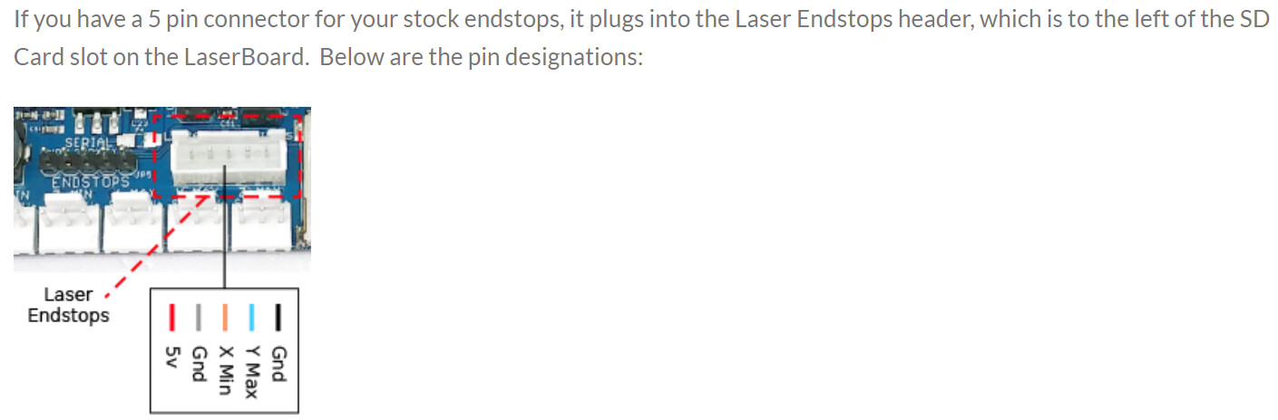
I assume then that the 2 common wires are G, then X min, and finally Y max. This makes sense for what we saw.
Try relocating the pins for X and Y. There should be a release at the top of the connector that allows you to pull out the pin.
Then plug back in and retest.