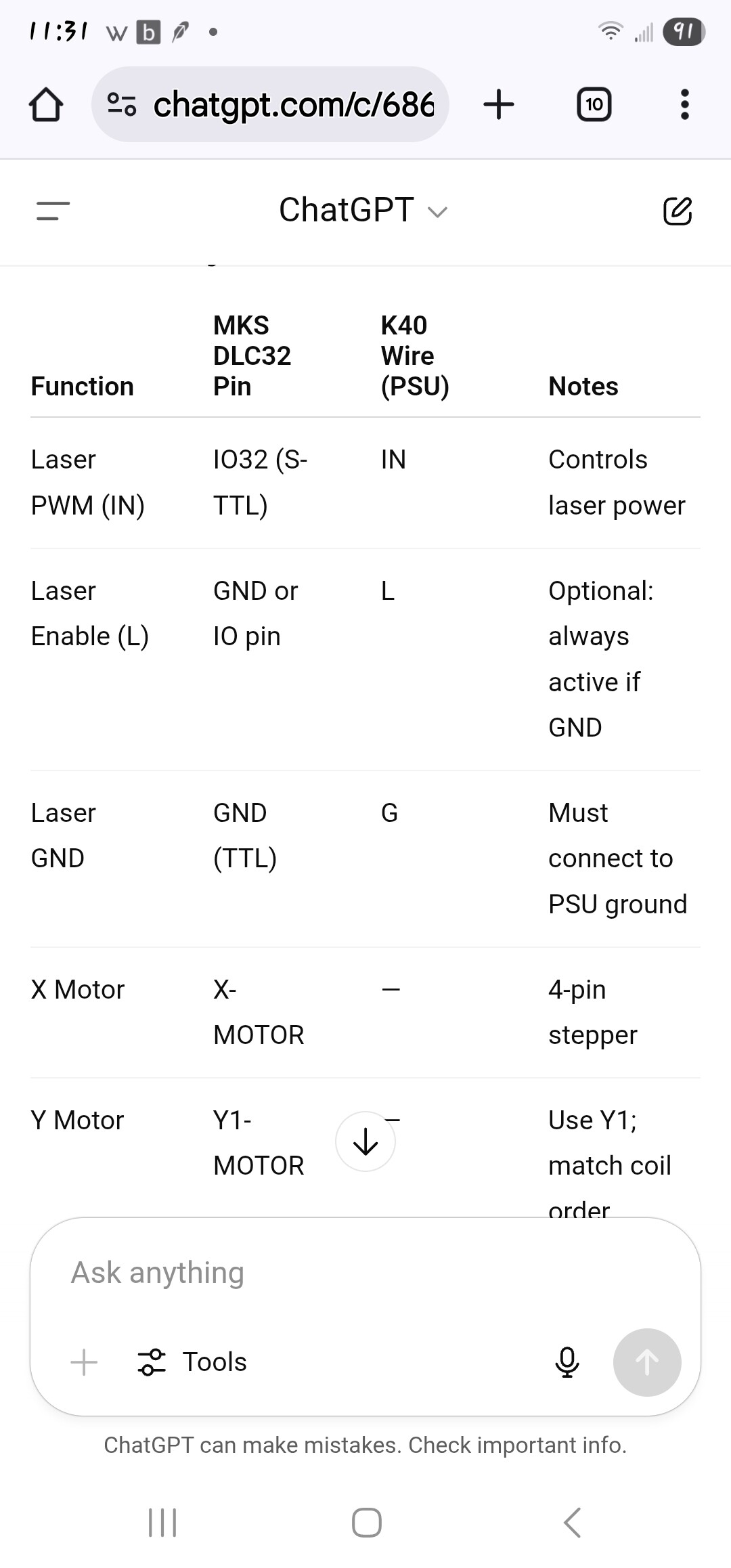
I have the gantry working through lightburn but the laser is constantly on i have tryed all the different wirings i could find on line all have the laser on what seems to be 100% the moment the controller turns on. The mks dlc32 is running stock firmware i could not get fluidnc to work correctly what do i need to change to get the laser to only fire when light burn calls for it and at the intensity lightburn calls for?
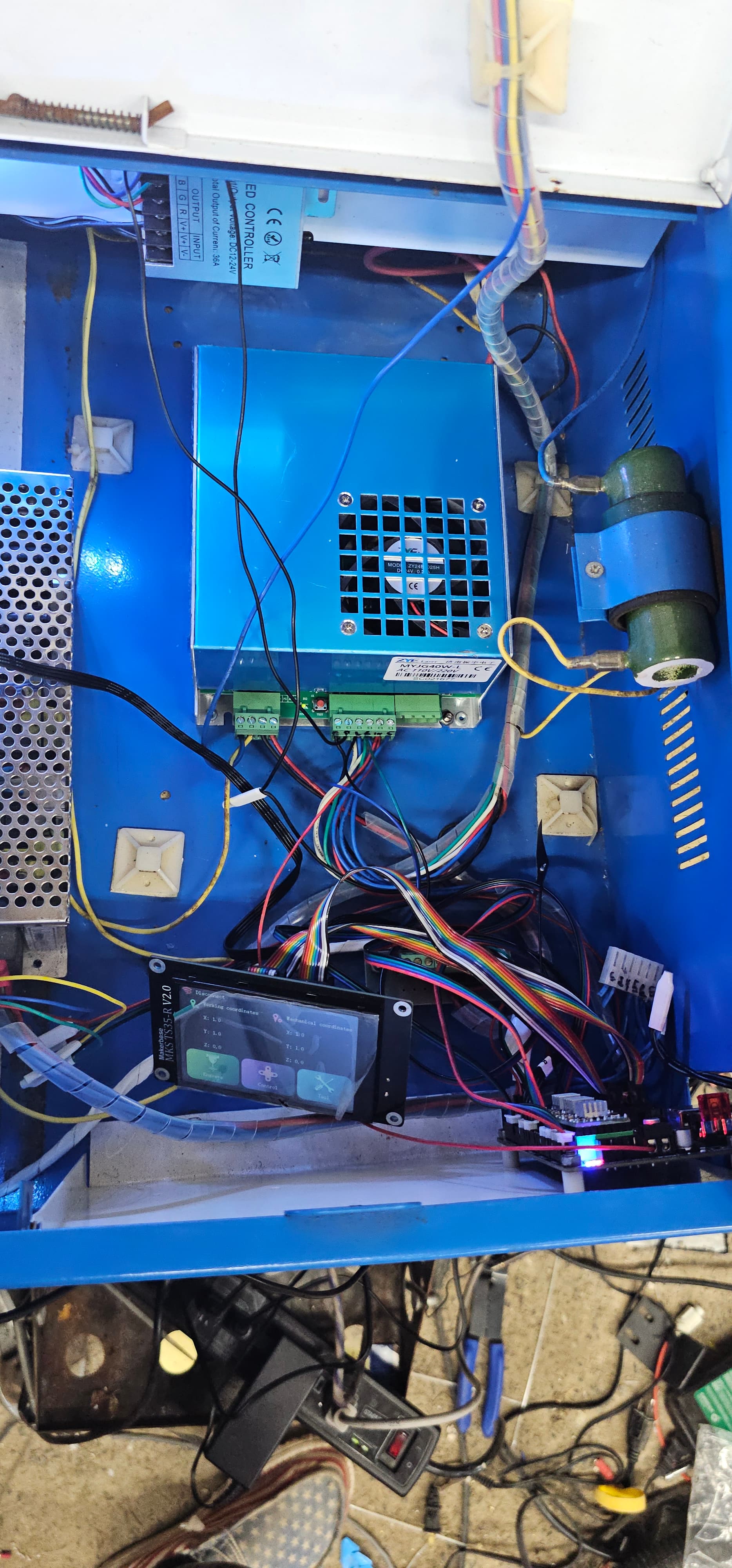
I have attached my setup the current wiring and lightburn settings Through playing with the laser power at 0% its on and at 100% its off so i need to reverse the output if i flash it to fluidnc and import the config i can do that and get the laser to work correctly but the gantry doesn’t work i get error 9 in lightburn. with stock firmware fluidnc wont load the config for me to reverse the laser output its been a struggle. thank you for any help been struggling to get this running for a veteran non-profit
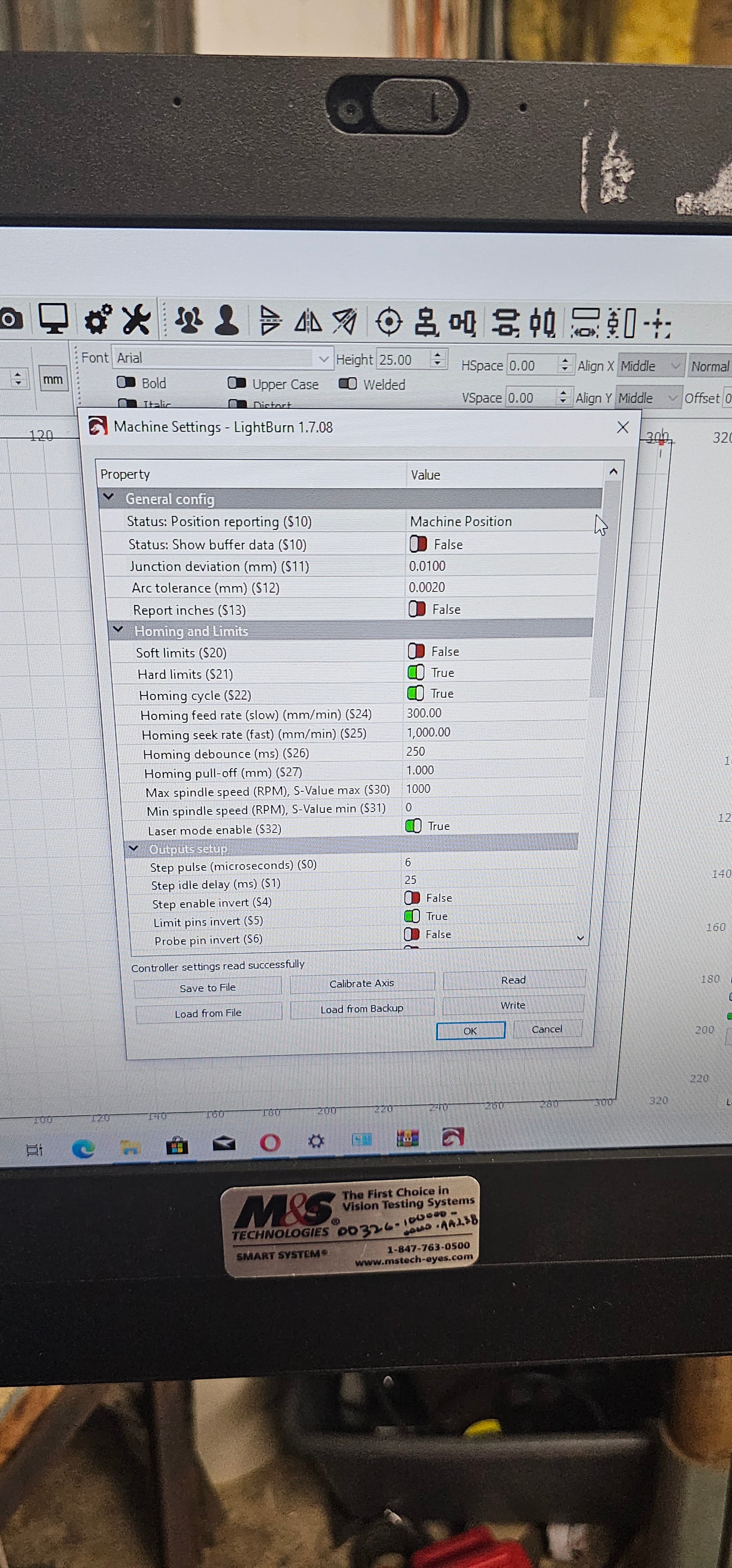
Through playing with the laser power at 0% its on and at 100% its of so i need to reverse the output if i flash it to fluidnc and import the config i can do that and get the laser to work correctly but the gantry doesn’t work with stock firmware fluidnc wont load the config for me to reverse the laser output its been a struggle
I tried one of those boards and went back to Arduino based board.
Be careful when asking AI about the pinouts of a controller board - I’ve been burned before.
There are many versions of this PCB. It’s best to look for the correct one here: MKS-DLC32/MKS-DLC32-main/hardware at main · makerbase-mks/MKS-DLC32 · GitHub
You’ll find a PDF with the name PIN in the respective folder.
Could you post the wiring diagram you used?
If you pull L on the LPS low, it will lase at whatever the IN pwm/voltage is. This is probably what you want. Do you still have a pot on the console? If so what are you doing with it?
I could never get mine to work with the console, I believe I loaded and ran with FluidNC software.
The DLC32 doesn’t have a laser enable output, so you have to enable the laser, I did mine from a switch and then the pwm controls the tubes power.
Pay attention to @Aaron.F – The only way AI works as expected is by ensuring you have feed it scrubbed data you know is valid for your application… It’s much better to deal with the devices manual.
I ran one of the AI against the laser isn’t firing. The results were to measure the output of the lps with a voltmeter ![]()
![]()
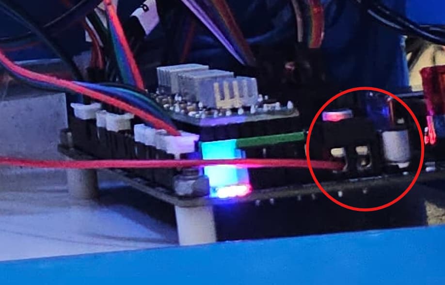
@WhiskeyRebellion1791 Wait, I see, you are using the “Spindle” output of the DLC32. And I don’t see a ground wire going from the spindle connector to the PS.
Also, it’s entirely possible, that you need to connect the LPSU using the TTL output instead.
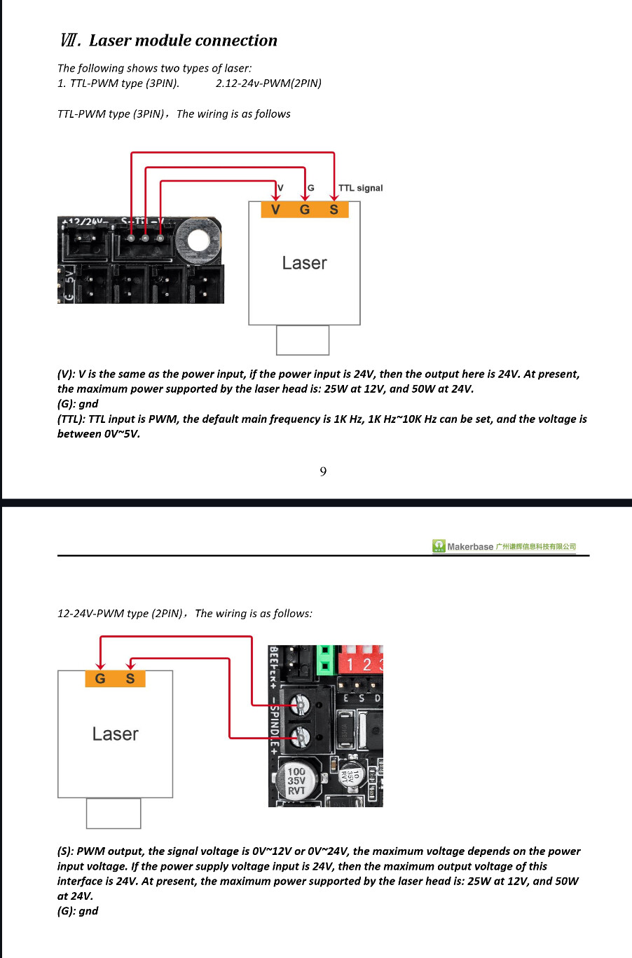
From the Wiring Manual:
Is this the power supply you have?
If you have a diode laser with only two connections (wires) it’s likely you can use the spindle. Most of us have diodes with some type of pwm control.
You probably don’t want to use the spindle connection with one of these.
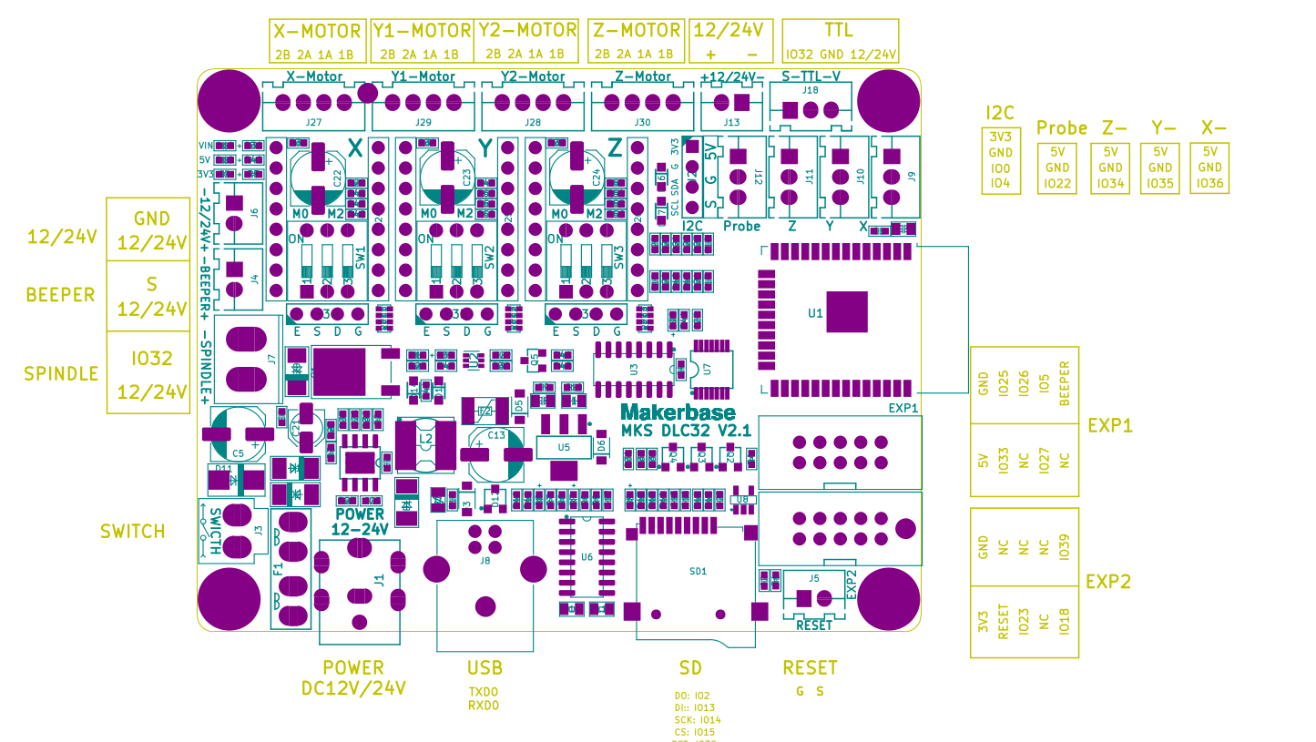
Reference the board and see what it’s doing. This is after the voltage translator as the cpu is 3.3V and most of these depend on the pwm voltage swing to go up to 5V.
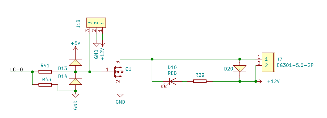
Spindle, J7 supplies board voltage tp J7-2, Q1 turns on when the pwm signal goes high. This completes the ground from J7-1. When the PWM goes high, J7-1 goes low.
I’d suggest you wire it up as specified by the documentation using J18.
If you run your board with a 24V supply, I believe these 12V items would reflect the Vcc of the board.
![]()