I got a K40 yesterday after my diode laser finally reached it’s end of life. I swapped the control board supplied from OMTech so I can run LightBurn on my Mac.
Here is the issue at hand;
Everything works splendid and as expected, laser moves with LightBurn commands.
Laser fires with the test switch on the K40
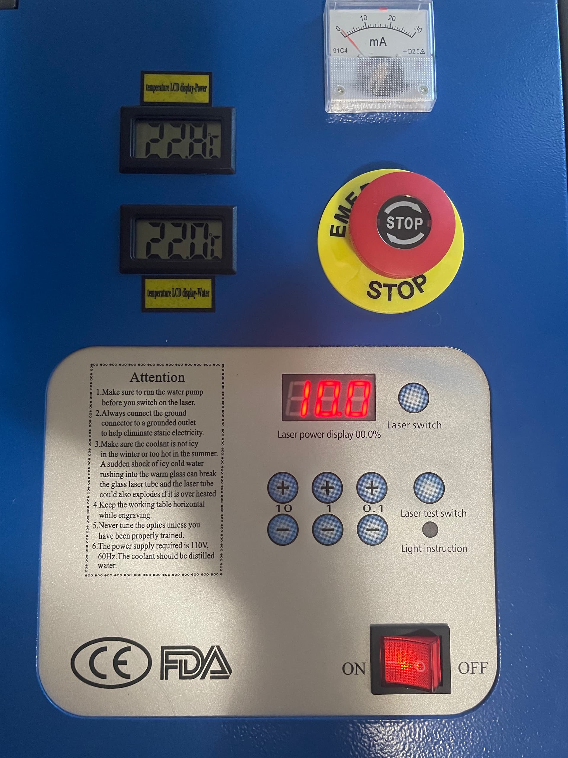
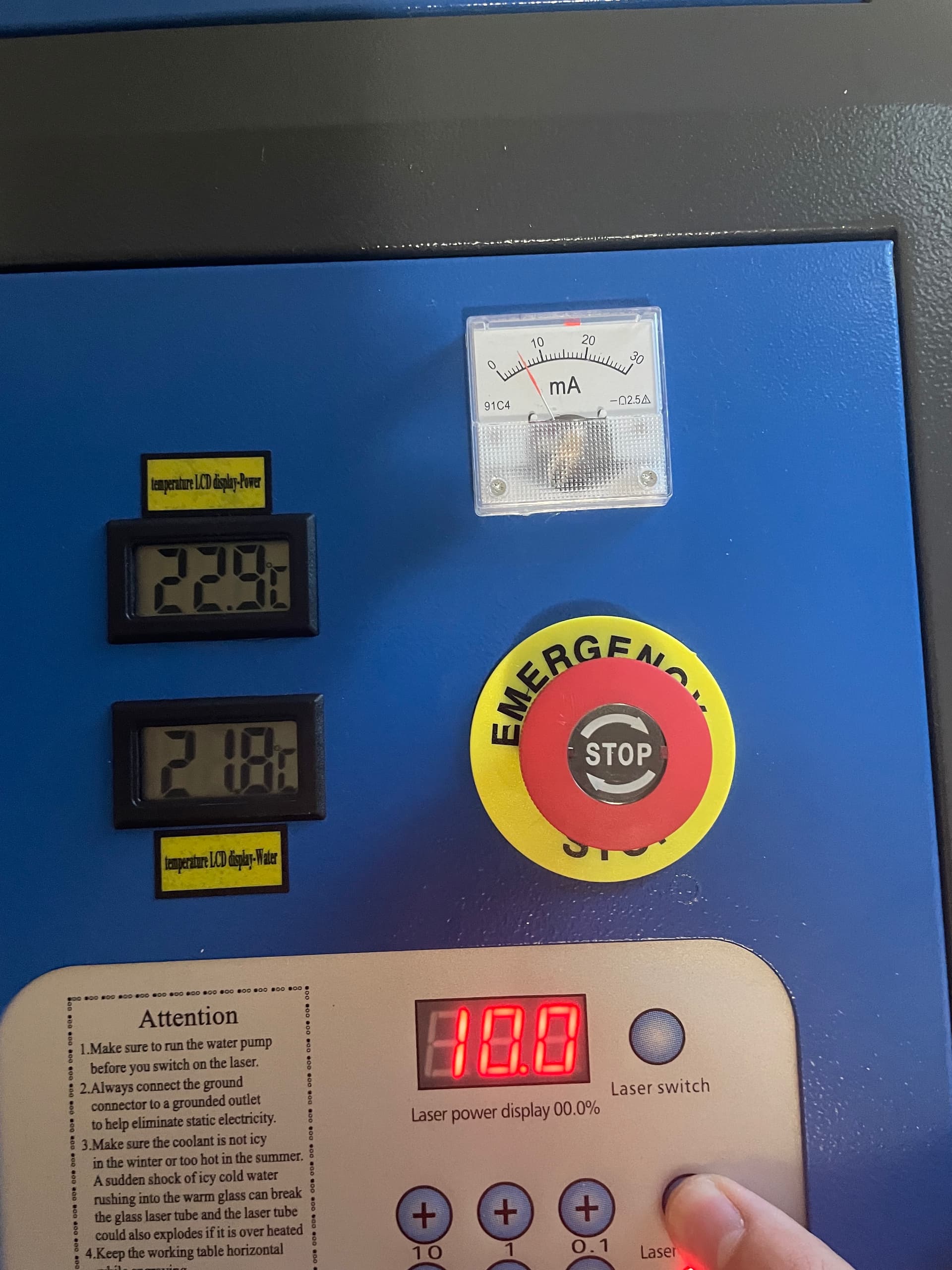
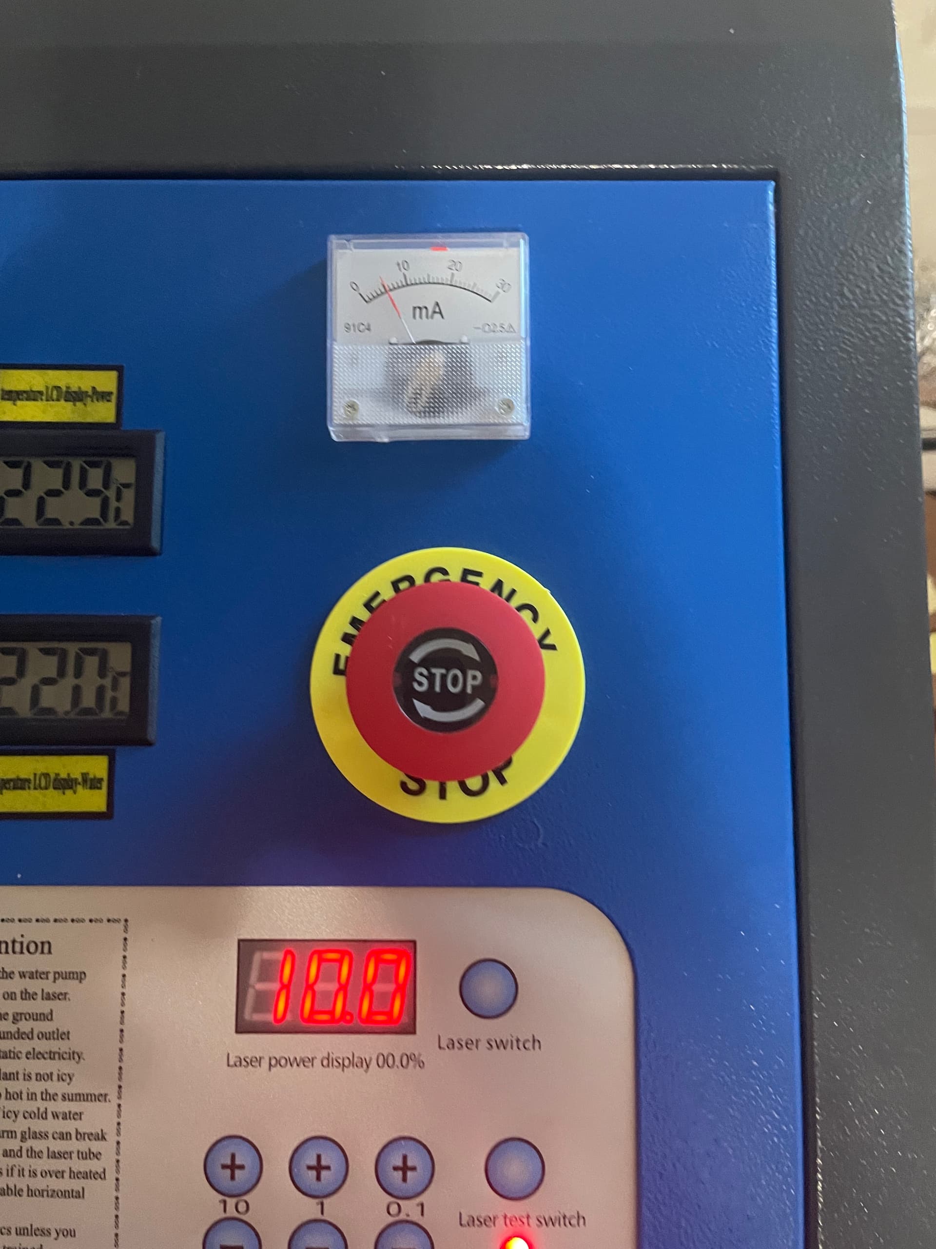
Laser will NOT fire using the fire button in LightBurn or if I task it to do a job, the head will still move around. The ammeter shows the expected output current for the power I have set but does not produce a beam.
Laser will fire on LightBurn if I depress the TEST button on the PSU
Is there a LightBurn setting that I am missing that will correct my issue, or is it internal troubleshooting?
I do not have a water flow sensor to cause a non fire issue, and the K- slot on my PSU has nothing in it, and the rest of that ribbon goes to the top panel display. I have two weird plugs on the back by my AC power supply that say they’re for a water pump, the wires seem to terminate inside shrink-wrap inside a wire wrap.
Ready to do any tests you guys have me and thank you for your help!
I set panel power to 10% tube had nice glow to it, produced a nice etch.
Set light burn power to 10% tube was very dim, left absolutely no mark.
Set light burn power to 50% tube was comparable to the 10% panel power test I did, etched similarly to the 10% panel power.
So I think my problem is that light burn is operating at roughly a magnitude 5 lower than my panel and that’s why everything has been confusing to me, and frankly I don’t know how to edit those settings either.
So I think I was just being dumb all night, a tiny bit of a learning curve that I had to go on.
I’ve been trying to run a project at 10% power on light burn because the 7% power on the panel etched very nice, and every time I fired on light burn I was basically outputting 0.7% and that’s why nothing ever happened. I don’t know my current rating on this tube but I’ll look into it, says it’s 40W but from my diode experience it could be different.
If I just set my panel power to 100% and control everything on light burn how I want, and am used to from my diode, I can get everything ranged how I want? I don’t plan to exceed 25% rated power for my applications. But then again, I could just set the panel to 25% and use 100% in light burn.
But you 100% helped me work through my dumb moment and I can take it from here now that I know what is going on!
You will become aware of the learning curve, like you are now, when you have ‘things’ happen that doesn’t seem right. Or isn’t acting like you think it should.
Comparing tubes to led is an apple to orange comparison when it comes down to it.
From your comment I think you are still unclear of what’s going on…
Keep in mind why and how ‘power’ is controlled on a laser and referenced. There is no 50% power, it’s really an illusion … If you set your power to 50%, it will lase 100% for 50% of the time. When a laser fires, it will fire at 100%, that’s the physics. You are applying ‘power/time’ to come up with what you refer to as ‘half power’.
The lps is controlled by two signals. The laser enable, ‘L’ and power control, ‘IN’.
The IN terminal is the laser ‘power’ control of the lps and can be used either with an analog or digital (ttl) signal. This actually controls the pwm of the lps, thus is the power control. To get the laser to fire there is an L input that is referred to as ‘laser enable’ in most references.
The dsp type controllers use both the IN (with pwm) and the L inputs to control the lps.
The K40 is lacking the L signal and uses the analog input (voltage, manual) applied to IN terminal. This sets the ‘power level’ or pulse rate of the lps. The K40s controller uses the pwm to turn this on and off with the L input. So in essence you are ‘pwming’ a pwm.
You have to set the lps pwm to some value with the pot, then you are using the pwm from the controller to ‘enable’ the tube for that percentage of power, on and off.
This is actually very clever… does away with the L control issue…
The theory is that you set the pot, probably once. Whatever that is set to is equal to 100% power in Lightburn.
I’ve been told it’s handy when the tube starts to go bad and they can re adjust it. I measure mine with a wattmeter if I notice a variation or I’ve cleaned the optics.
The failure here is that the when it lases, it lases at whatever current the lps can supply. The assumption is the meter is telling you the actual current when in fact it is being pulsed. It’s actually displaying the rms value of the signal. The rms value of a 50% pwm signal is virtually half the actual value.
The Ruida has a control panel that allows a few adjustments for manual and override of the ‘programmed’ values. I set mine at 50% pwm and lased it long enough for a stable meter reading.
I noted it was 14mA. I’m reading half of the supplied current or 28mA. My maximum is 21mA, the only fix is to reduce the current on the lps itself. Most have an ‘adjustment’ and I lowered mine to 10.5mA at 50% power. Using 50% power levels make computation easy and ensure you don’t drive the tube hard just setting it up. I’m still very aware that I am running 21mA through it when it lases.
Are you thinking you have too powerful of a laser for the application?
Don’t shoot yourself in the foot…
Speak up if you didn’t follow any of this. I tried to make it as short as possible and simple, only you can tell me how it did with that tact. I also didn’t go into the lps response time, that isn’t an issue with led types.
As for application, most of what I am doing is engraving and cutting 1.5mm baltic birch, occasionally I will do that on 3mm MDF too, I’m about to play with the laser so I can see what my engraves and cuts will look like.
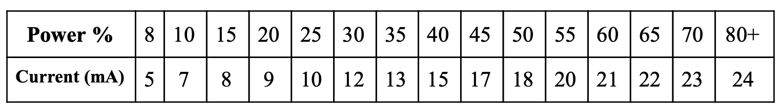
This is the current to power scale that they have in my manual
The controller installation manual makes no mention of how the controller interfaces with the lps.
I don’t have that controller and I’m assuming how it’s wired, as it appears you don’t seem to know^… I’d recommend:
use lightburn to create a single vector line that’s long enough to get a stable reading on the mA meter. I uploaded the one I use.
set the layer in lightburn to 50% power.
‘run’ the line and adjust your ‘console power’ to get 1/2 maximum mA
leave the power adjustment on the console alone until you need to, a year or two.
From what I can see, kind of uncomfortably, but I’d guess that somewhere in the 15 mA range is good for a 40 watt, but I don’t know. That means on step 3 the ‘1/2 maximum’ would be 7.5mA.
make sense?
There are a number of people here with those machines and they could advise you on the ‘area’ in mA you could use as maximum or you could google it. The best is what the factory tells you but that’s not always available… sometimes with this stuff you do end up making an educated guess. That’s why I picked 15mA, probably on the low side.
I keep this file in my ‘templets’ I use it for figuring out focus (ramp test) and such things as the proper speed and cut rate combination. You can use it to set up your max power on the console. Might have to make the line shorter or longer.
^ I’m not picking on you, it’s just fact, probably 99% of the people out there wouldn’t know or care how it’s wired. That’s why I ask if you understand, helps me access your technical level.
Oh yeah, I figured it out. Playing around making my little tokens. I set my console to 20% and let light burn take care of the rest, can make them drastically faster than I’m used to with better quality.
Going to make a new shade scale thing to pin on my cork board.
Great… you should still chase down what current level is maximum and change the lps current control to restrict current to it’s maximum.
Did you follow what I advised or just set it to 9mA … to be safe? It’s more difficult to understand what happened if you are not more specific about what you did and where.
The 20%/9mA numbers seem a little off to me… What size lps do you have?
If you had this problem and it was solved by you, no one would know what fixed what…
If you are trying to get ‘longer’ tube life… these are ‘consumables’, they will die from sitting and not being used as well as used correctly. You should be comfortable at 70 or 80% or you will severely handicap yourself from what you can do along with the quality of your work.
You can ‘cut’ your mdf at many different power/speed combinations. It will cut best at a specific power and speed. One setting may leave ‘carbon’ when you touch it and your fingers are black. If you adjust the power/speed correctly, you can wipe it with a white paper towel and find little if any carbon… correct power/speed combinations are really the name of the game. Identical to any other cnc, speeds and feeds…