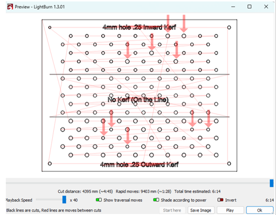
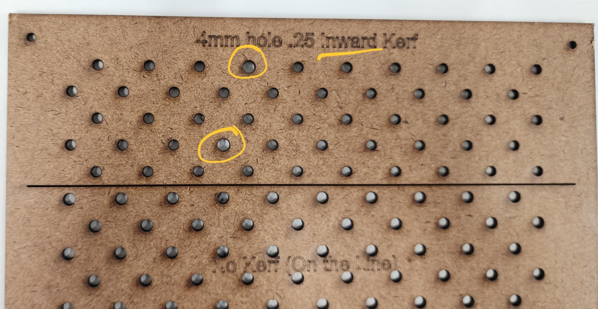
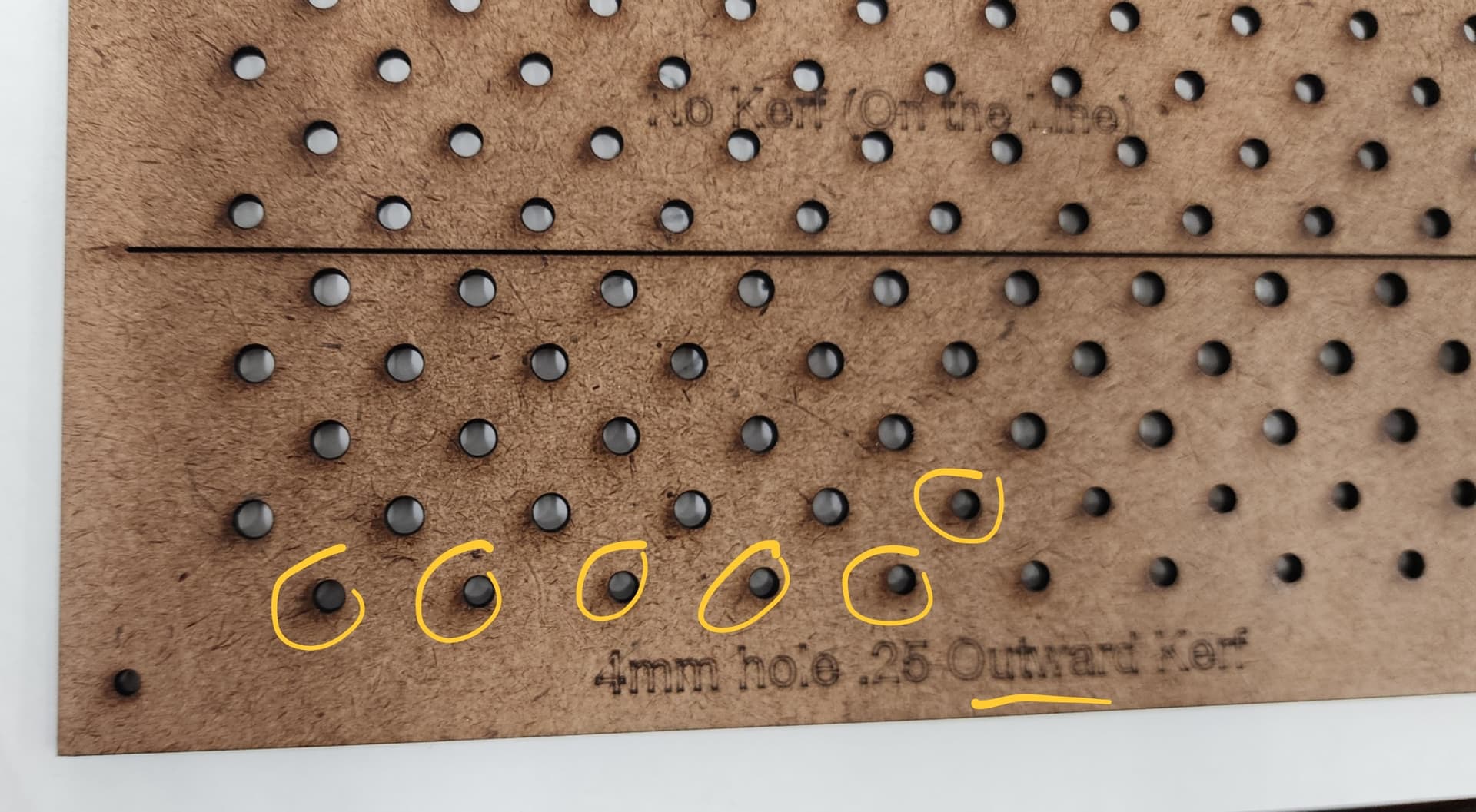
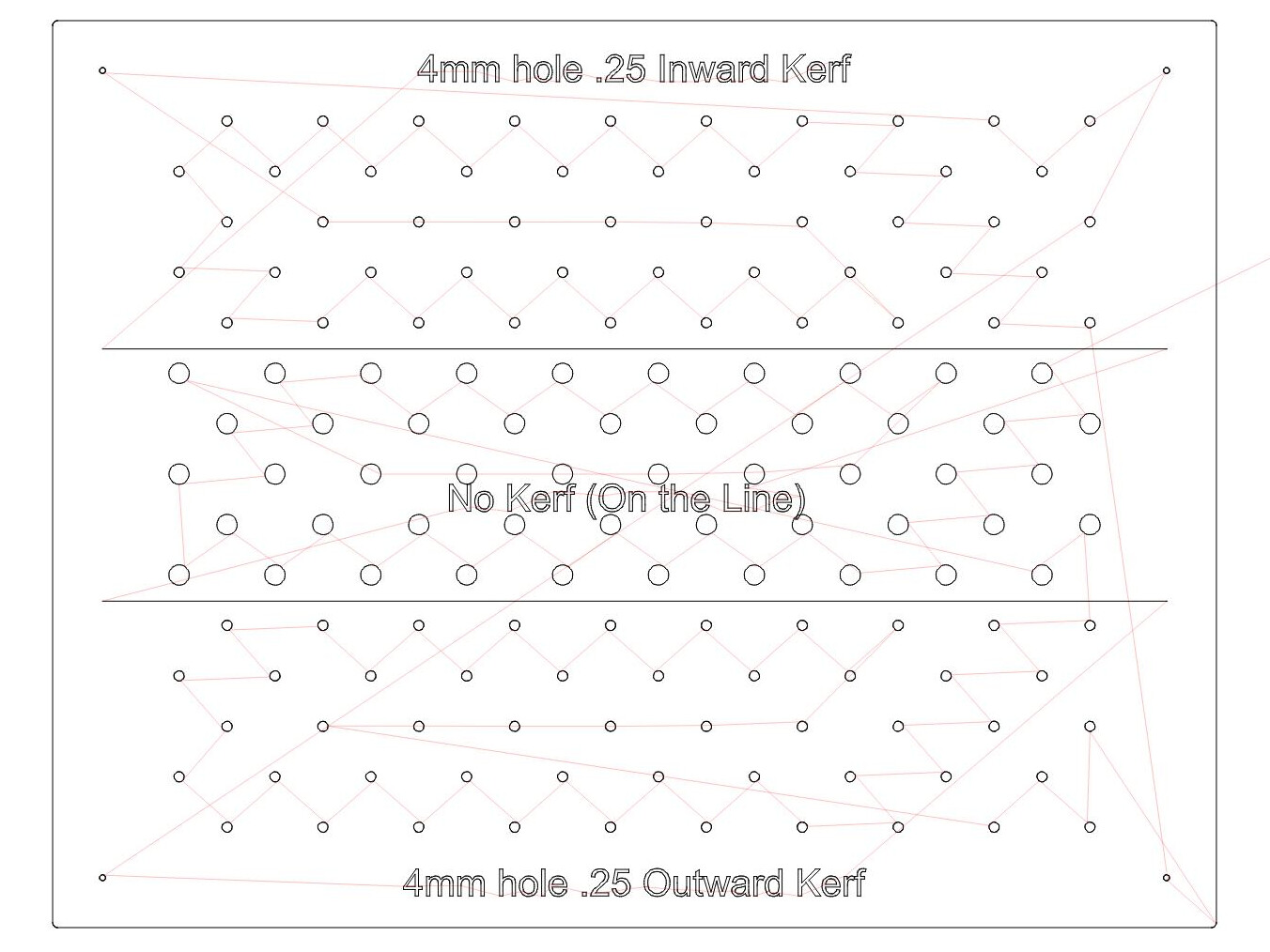
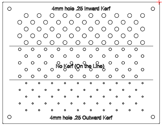
Kerf Question: I’m using 0.25mm kerf offset for my AF lenses. I need better accuracy than just “cutting on the lines” I don’t understand why I’ll have random vectors of a copied circular vector in an array (all the same) that cut differently. In my example, I have the top 1/3 of the 4 mm holes with a inward kerf,
the middle 1/3 cut on the line, and the bottom 1/3 with outward kerf.
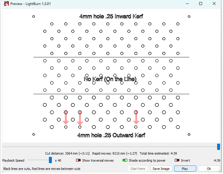
Even the preview shows the output is not what is desired. When the material is actually cut, the random incorrect kerf correction cuts are also random on the material - not matching the mistakes in the preview. It does not matter if the file is transferred over Ethernet, USB, or direct from light burn to the laser CNC.
Ah! The nightly simulation run explains what happened …
The bottom set of circles are inside the outer rectangle in the same blue layer. That makes them holes, so the layer’s outward kerf applies to the surrounding space and makes them smaller.
The top set of holes are not inside anything, so the layer’s inward kerf makes them smaller.
Change the outer border to the black layer and all the circles behave properly.
Which does not explain the random sizes you saw, but at least the rest of it is working as intended here.
No outside box, still the problem happens on mine. On CNC mills, when making pocket cuts between two vectors, making certain both vectors are closed is very important. But I don;t see why a single closed vector, if it is or is not inside another closed vector, is relevant? The software is only cutting based on one vector at a time in this case. Not an area between two closed vectors. I’m really trying to not think like a mill CNC here… I don’t understand how your simulation runs differently? Even more perplexing is the random locations of the wrong side cuts. Works perfect on the lines only (no kerf)
The standard way of figuring out whether this object is inside that object is to cast a ray from it to infinity and count the number of border crossings for that object:
An odd number = this is inside that
An even number = this is outside that
I can conjure situations where casting the test ray at some specific angle from this circle kisses that circle juuussst enough to count as a single crossing, thus putting this inside that, even though they obviously aren’t nested. Erratic results can come from numeric instability jittering the calculation; floating point numbers behave that way.
Which sure sounds like a Just So Story to me, too, but it happens in 3D modeling a lot. You may have inadvertently created a bizarre testcase with exactly the right size circles at precisely the right spacing in the exact layout required to trigger the detonator.
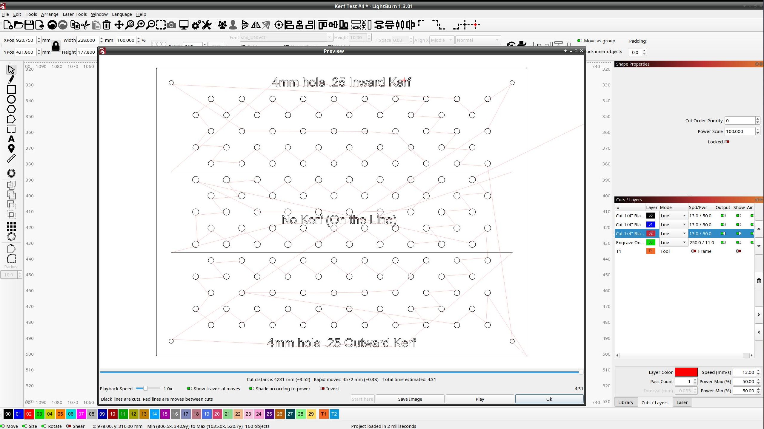
Of course, your testcase #5 previews exactly the way you might expect on my machines.
We’re both running 1.3.01, although I expect you’re using some flavor of Windows and I’m using Manjaro Linux.
I made this test file ultimately from a need to fab up a quick board to hold a bunch of screws to paint. My jobs are typically making dash panels for boats out of black acrylic. I’ve made hundreds of panels on a mill CNC. I’m very familiar with pockets and outside/inside cuts as a 1/8" or 1/4" end mill takes a lot of material away. Pockets can be tricky to be certain that inside and outside vectors are closed. But wouldn’t each circle be considered individual? Say I have a doughnut, a circle with a smaller circle inside: If I tell my mill to cut the outside of both lines as either individual vectors or a group, that’s exactly what happens. A pocket cut would take the space between the two vectors and if the vectors touch or overlap, crazy math happens like the square root of a negative irrational number is divided by zero. LOL
I’ve read some other posts about “fill” layers which to me sounds like pockets. Then it’s something like each pair of vectors would be an outside, then inside boundary for the fill starting with the innermost vector… something like that. But these vectors are not within another as with my “kerf test #5” file. …and it still does it and none of the layers are fill type either.
I have a real example of a recent file I cut 1/4" black acrylic. Never could get my preview to show the clear fault as the screw card file is clearly illustrating, but I had to cut this 30" by 12" panel 3 times before the 12 screws holes were correct. The first two panels each had 1 hole with outside kerf of the 12 holes that all should have been with inside kerf. Different location - no change to the file. 3rd cut did it right. Wasted a lot of money in time and material! Rev 2 SeaRay Dash Panel Twin Axiom_backup.lbrn2 (30.1 KB)
What is your reason for running in Linux?
I going to look to see if it is feasible & stable to run Linux inside a Windows 11 environment. My shop is entirely in a UniFi / Windows 11 environment. I haven’t dedicated a computer to the OMtech CNC yet and my learning period for work has been off my laptop for now. I like to RDC to other computers in my shop so I would prefer to keep all Win11 (unfortunately).
Ed, I greatly apreciate your input and help! Thank you very much!!!
However, what’s obvious to us, with our bird’s eye view of the design, requires an algorithm to extract from a pile of geometric entities and coordinates.
CAM is where you inject your knowledge into the machining process: the tool offset is on the inside of this circle and on the outside of that circle.
Without that knowledge, The Algorithm must cast a ray from a point on one circle and count how many times it crosses the other circle … and fumbles when the ray kisses a circle way over there that’s obviously not enclosing anything, as seen by the bird.
You should take this up with support@lightburnsoftware.com, because The Algorithm will definitely benefit from your “testcases”.
The Offset tool lets you manually define the “tool offset” for specific objects, which would let you set the kerf for those holes forever more. It’s not quite as easy as a layer-wide kerf, but IMO the predictability outweighs all other factors.
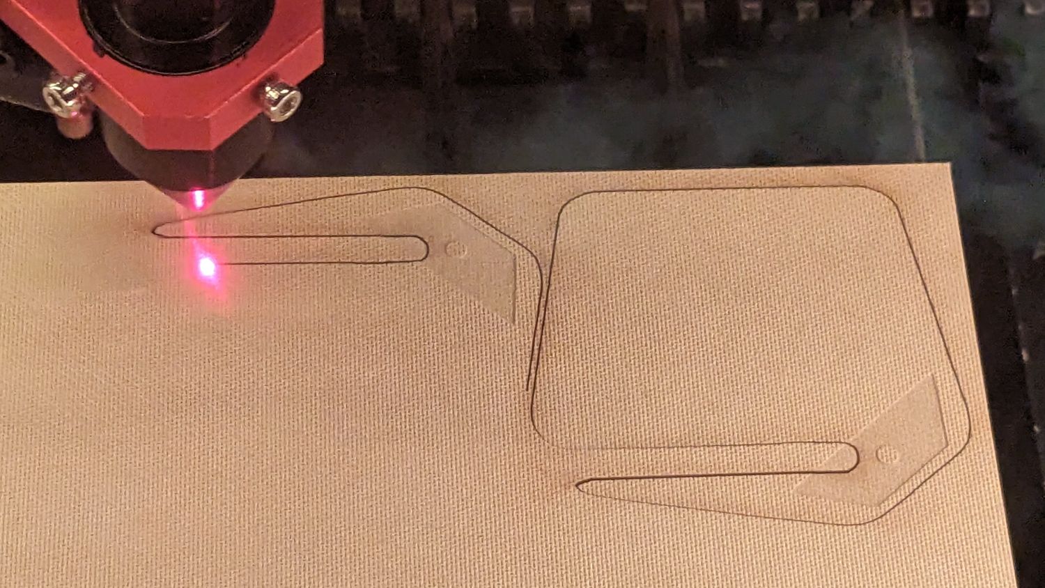
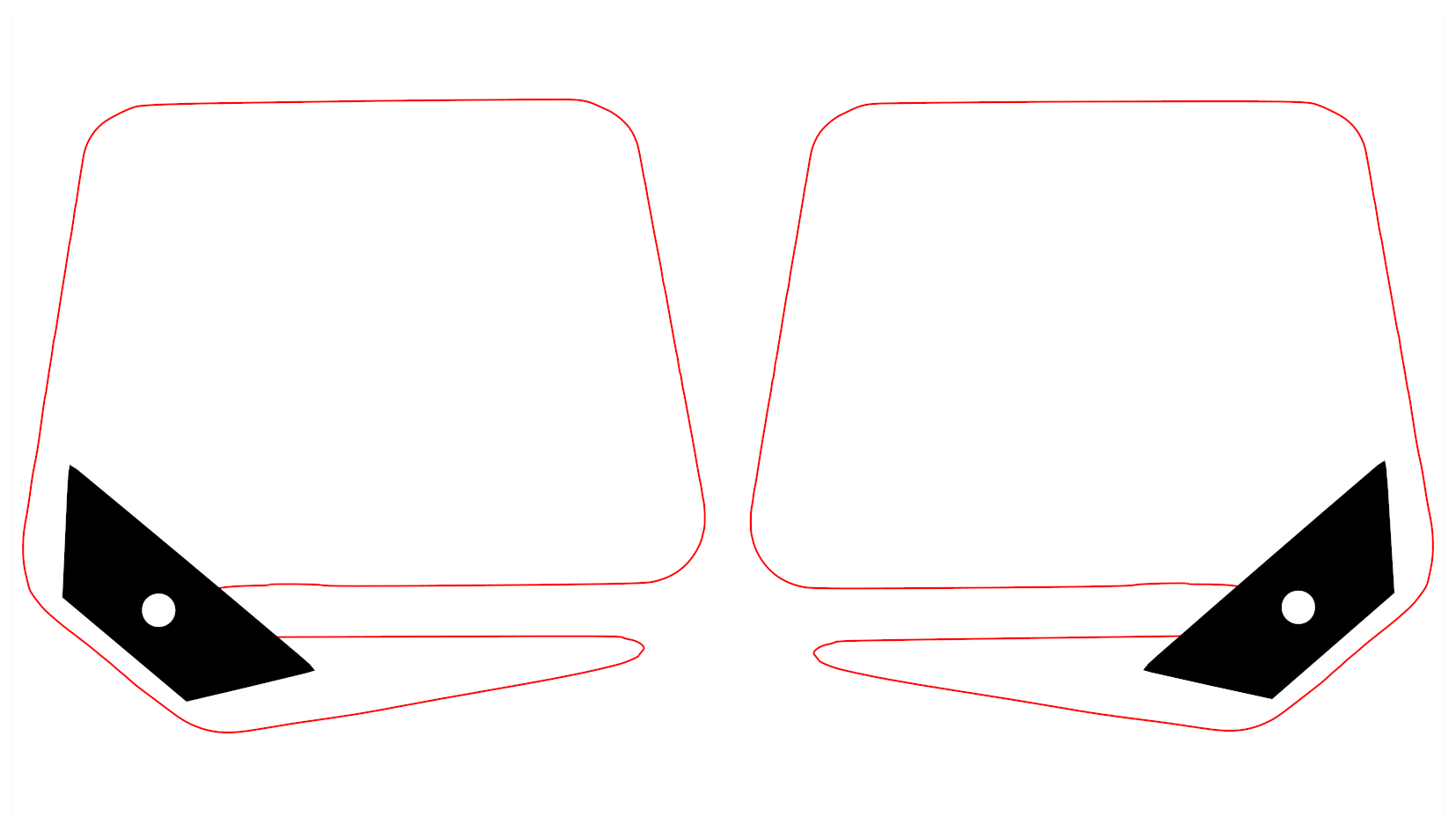
Which is exactly what they are:
The nearly invisible shapes are 0.25 mm pockets capturing the blade in a letter opener.
When the software breaks, I have all the pieces and can (generally) get it running again. It’s admittedly an acquired taste, but the stability and lack of malware compared to the continuing chaos and adware of Windows definitely counts.
And you can remote into a Windows box from Linux just fine. We have a Token Windows Laptop for TurboTax (and a few other resolutely incompatible programs) that I access from my Comfy Chair through RDC / VNC / whatever, which is much easier than crouching over that keyboard.
It’s possible that the version of LightBurn you’re using has a bug - we’ve found a few cases where the inside / outside sorting of layers wasn’t correct because of code changes introduced when we added sub-layers.
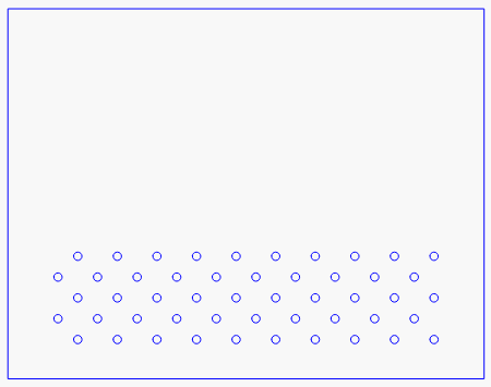
Aside from that, the inward / outward behavior you’re seeing is at least partly due to how LightBurn handles shape groups and layers. When you tell LightBurn to order things by layer, it processes each layer as a separate entity from everything else. Your red and blue layers look like this:
The red holes aren’t inside anything, so they’re “outer” shapes, and an inward kerf moves into the shape itself.
Since the blue holes are all inside a blue rectangle, they’re treated as holes in the blue rectangle, so adding an outward kerf, toward the outside of the shape, moves them into the empty space within the hole. If you didn’t have the blue rectangle around them, it wouldn’t do that.
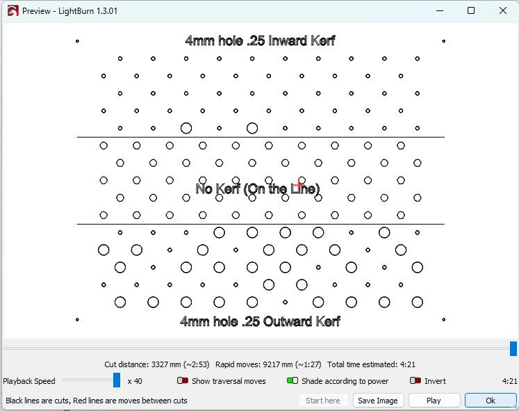
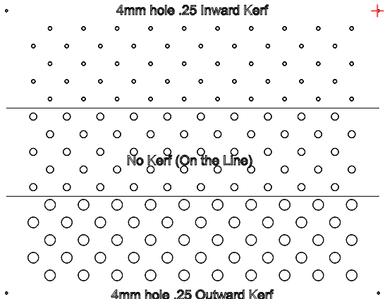
If you remove the ‘Order by Layer’ optimization, all layers are processed at once, and then the behavior is consistent:
In this case, all the holes are inside the blue rectangle now, since layers no longer matter, and the kerf offsetting is as I’d expect. If the blue outer rectangle is removed, they all flip:
Ed & Oz,
I didn’t want to be that guy that leaves the thread open after the solution has been found. GOT IT!!!
I now have a much better understanding of this amazing software. It’s still a little difficult for me to un-program my brain from other software I’ve used for years. The order by layer optimization changes is now giving me consistent results. I’ve learned other features along the way too!
I can’t thank you guys enough!
Paul