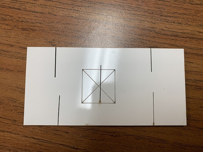
I’ve really been working on tuning my 150w CO2 laser to maximum efficacy. Spent a lot of time perfecting mirror alignment, making sure my cut bed is flat and consistent distance from the lens. Mechanically I’ve got everything as close to perfect as I think I can get, but I’ve noticed now when I’m doing my focal tests no matter what I seem to do the kerf of my cuts and engraves at the top left corner of the machine is always at least 2-3x as thick as everywhere else on the cut bed. Again, focal distances to the material are all the same. Beam is aimed, mirrors and lenses are clean. Is it just cutting that much more intensely up by the emitter because it hasn’t travelled as far? The result of more concentrated power density? Is there any way to compensate for this? Ideally I’d like my kerf to look consistent across my cuts so I know my hole sizes and dimensions are consistent. Attached is an image to illustrate the issue. Each of the corner cuts represent the same power and speed settings as well as focal distance. 20mm/s 85% power. 150w. Material is MDF. The bed size is 1300mm x 900mm. Has anyone else experienced this?
As the bed size increases so does the span of travel for the laser beam, but there should only be a slight variation in power comparing the top left (shortest path of light) to the bottom right (longest path). This variation on any machine can also be made more dramatic without the use of GOOD and effective fume extraction (especially if working with wood producing a lot of smoke).
What you pictured looks to me like an optical alignment problem. I had similar variation in power across my 900 x 600 bed until I spent literally hours calibrating the optics. It is a lengthy task. Adding to it all, you must verify that the beam (once passed through the lens) is clearing the nose cone of your laser head.
As your laser head is moving along X and Y, ever so slight changes are occurring in the light angles. It is possible that the upper left corner is unobstructed by the cone while the lower right is indicative of the beam interference within the lens holder nose cone. Try testing a couple of shapes at the extremes without the nose cone attached and see if that improves the consistency. If so, you know that your problem is the dreaded optical alignment.
Can you elaborate more on what you mean by “Calibrating the optics” that sounds different from alignment.
Considering some of the definitions of calibrating:
- adjust (experimental results) to take external factors into account or to allow comparison with other data
- to adjust precisely for a particular function
I think there is more to optical alignment than “meets the eye”, but essentially that’s what I am saying (alignment).
But understand that you’re not aligning in or at one point. If you’re working on X (for example), then once you think you have dialed that in, you have to move X from one extreme to the other and observe the change in beam angles.
I used a reverse laser when doing mine along with a fog machine, but that was surely to the extreme. There are several posts here on the forums detailing optical alignment. It is not fun. And the larger the machine, the harder it is to do well across the work area.
Gotcha, thanks for the insight.
I meant to link to this as well:
This topic was automatically closed 30 days after the last reply. New replies are no longer allowed.
