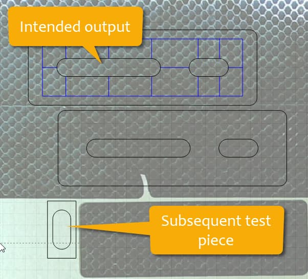
I thought I perfectly understood how the kerf offset works but in practice I am getting baffling results. It has been my understanding that you would use a positive value to account for the laser beam width so that both internal and external features would end up at the desired size. Here is exactly what I have done and the results. I cut a 1.000" square with zero offset which resulted in a size of 0.990" actual. I then entered a positive Kerf Offset of 0.005". I then cut my intended design which is a router template and I designed the bushing slot to be 0.630" wide for a 0.625" diameter bushing. The resulting slot measures exactly 0.620" which seems right IF the cut were negative. This is not the desired outcome. I then entered negative 0.005" and cut again. This time the slot came in at 0.640" and the loose cutout does indeed measure 0.630". Neither is what I am want. So please advise me how I am to properly use the Kerf Offset in this context.
It would help to see exactly what you’re working with. I just tested with a simple rectangle and negative kerf made it smaller and positive kerf made it bigger. Post a screenshot of your Lightburn and possibly also upload your file.
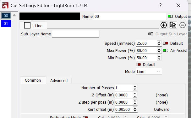

It’s easy to get disoriented as to whether a kerf + or - is moving the line outward or inward
When I’m not certain, I just enter an absurdly large value like 2mm and check out the preview window, it will be very obvious which way + and - is moving it in that context so I can go back and enter it right
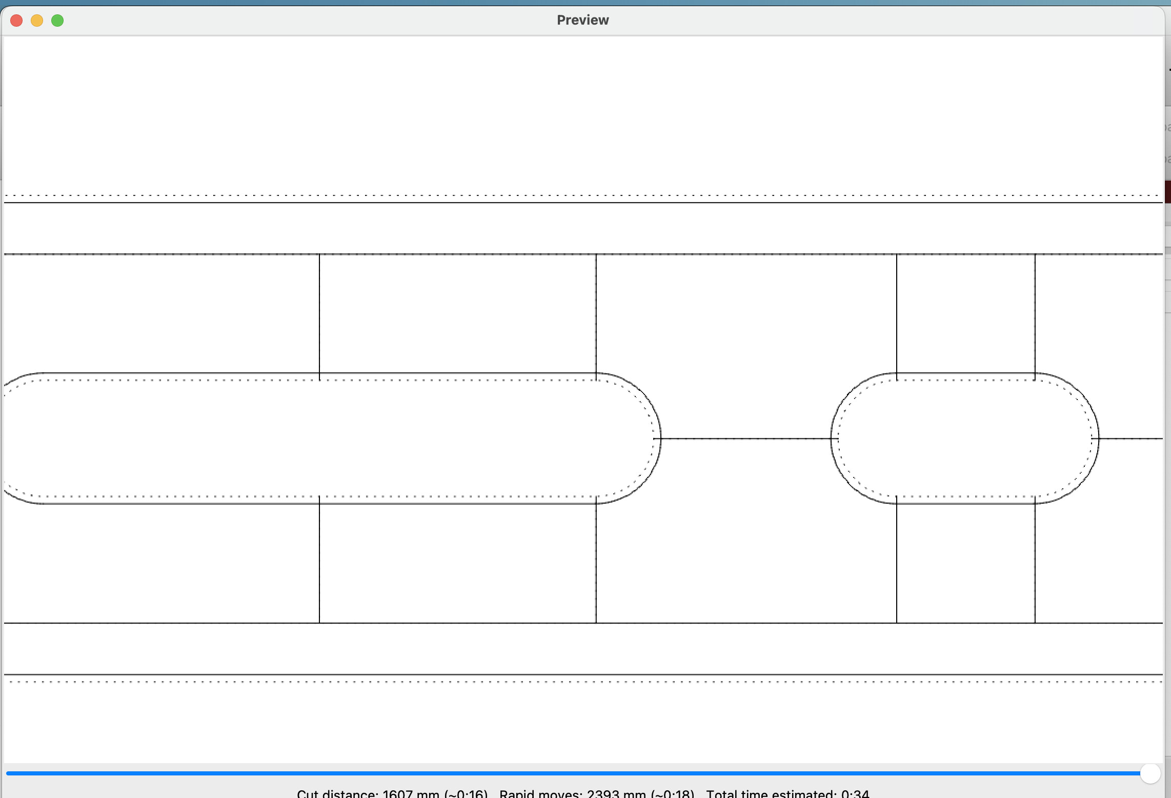
Let’s see if I can explain what it’s doing. It has something to do with hainge the entire shape cutting, Lightburn is moving everything toward the middle of the cut area. If you only select the oval, it makes it smaller. Better explained with pics.
I duplicated your shape and made a perforated layer of the duplicate with no kerf offset(dotted line is the original shape) and put a negative kerf offset. You can see how it will cut in the preview.
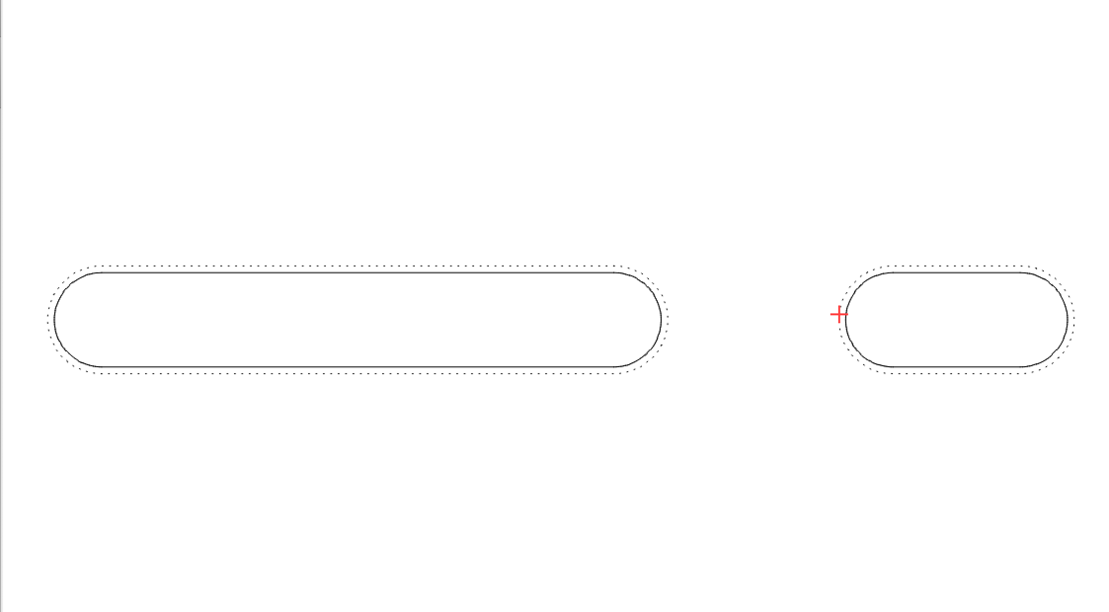
Here I only select the ovals with the same negative kerf offset. See how it handles them differently.
I ran yet another test using the small slot and then a 1” x 2” boundary with zero offset. Both external dimensions measure 0.010” small (as expected) but the 0.630” slot width measures 0.632” (an acceptable deviation from perfect). I don’t understand the discrepancy here between external and internal dimensions.
Notice how both offsets ar either going closer to each other or farther away from each other. That’s what happened with your graphic. The outer offset and the inner offset went in, making your hole too small.
The best way to see what is going to happen, in my opinion, is to copy the shape to a dotted line and use an extreme number kerf offset for visual aid in the preview window. Then, once you know which direction it will go, set the correct offset and delete the dotted line.
What is a kerf and an offset? When I cut 3mm tabbed boxes with my 10w laser using 2.8mm Baltic Birch, the tabs fit the slots perfectly. ![]()
and an important point is there may be consequences to how you do it.
For example, we often separate inner cuts off in one layer just so they go first, then follow with the outer cuts.
That would reverse the kerf direction for the inner cuts, since, on the layer they’re on, they are now the outer, not inner.
This is another way to handle it. You probably don’t need the kerf offset on the outer cut. Assign it to a different layer without the offset to cut after the inner cuts.
That is also accomplished via the optimization settings without needing to separate via layering (to cut inside shapes first). I am still not understanding why the software isn’t simply doing what it says it does. The online documentation illustrates that a positive offset adjusts the beam to be offset by the kerf offset amount (the beam diameter) to the outside on an external cut and to the inside on an inner cut without needing to go thru the additional steps of layering. I must be missing something here but I am merely going by what the software says it does.
I saw your post on Facebook and see that you still are having difficulty wrapping your head around this. I choose to respond here as thing get lost too easily on Facebook.
The issue is Lightburn treats a complex shape and a simple shape differently. Let me try and explain, at least to the best of my understanding. When you have a complex shape and request a negative kerf offset Lightburn takes that to mean you want everything smaller, so it moves the kerf inward away from the lines, which, in effect makes the inner holes larger when you thought they would be made smaller. A positive number does just the opposite, making the holes smaller. It’s expanding or shrinking the complex shape.
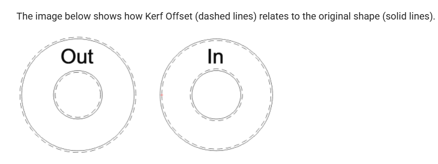
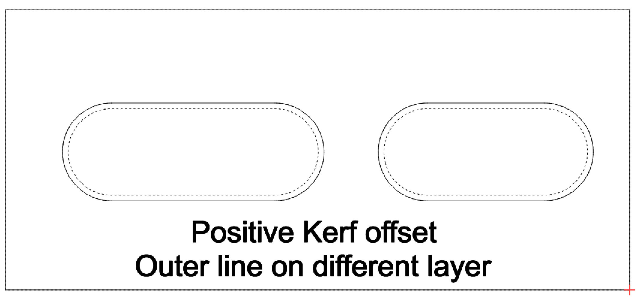
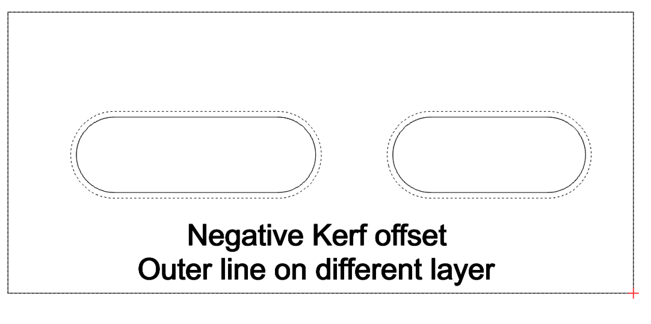
When dealing with a simple shape it works as you expect, negative makes the holes smaller and positive makes it bigger. Look at the screenshots below. The dashed line is the original shape without kerf adjustment for reference, the solid line is what will actually cut.
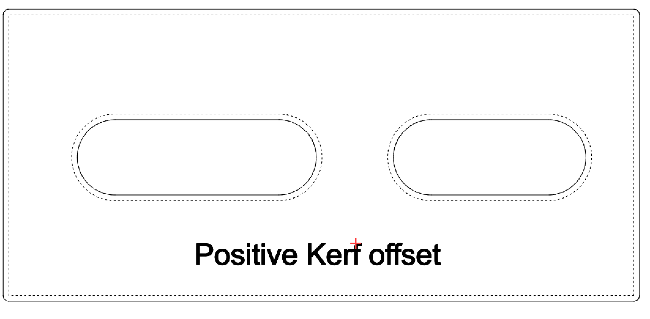
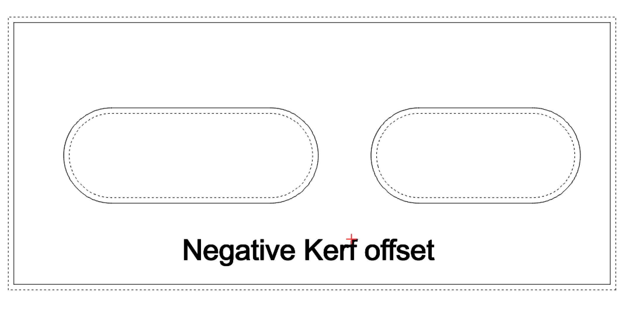
The first 2 images are your complex shape(all lines on the same layer) with kerf offset applied. Notice how it makes the entire cut area smaller or larger depending on pos. or neg. kerf.
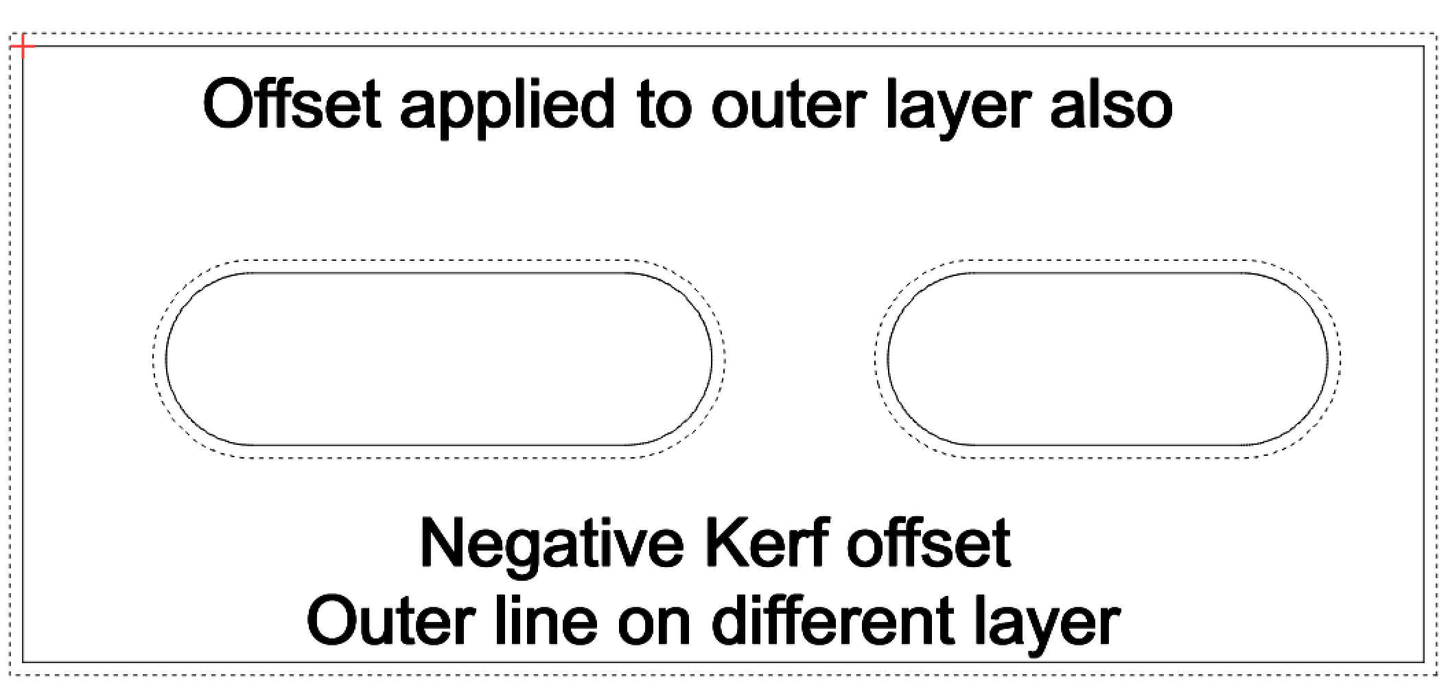
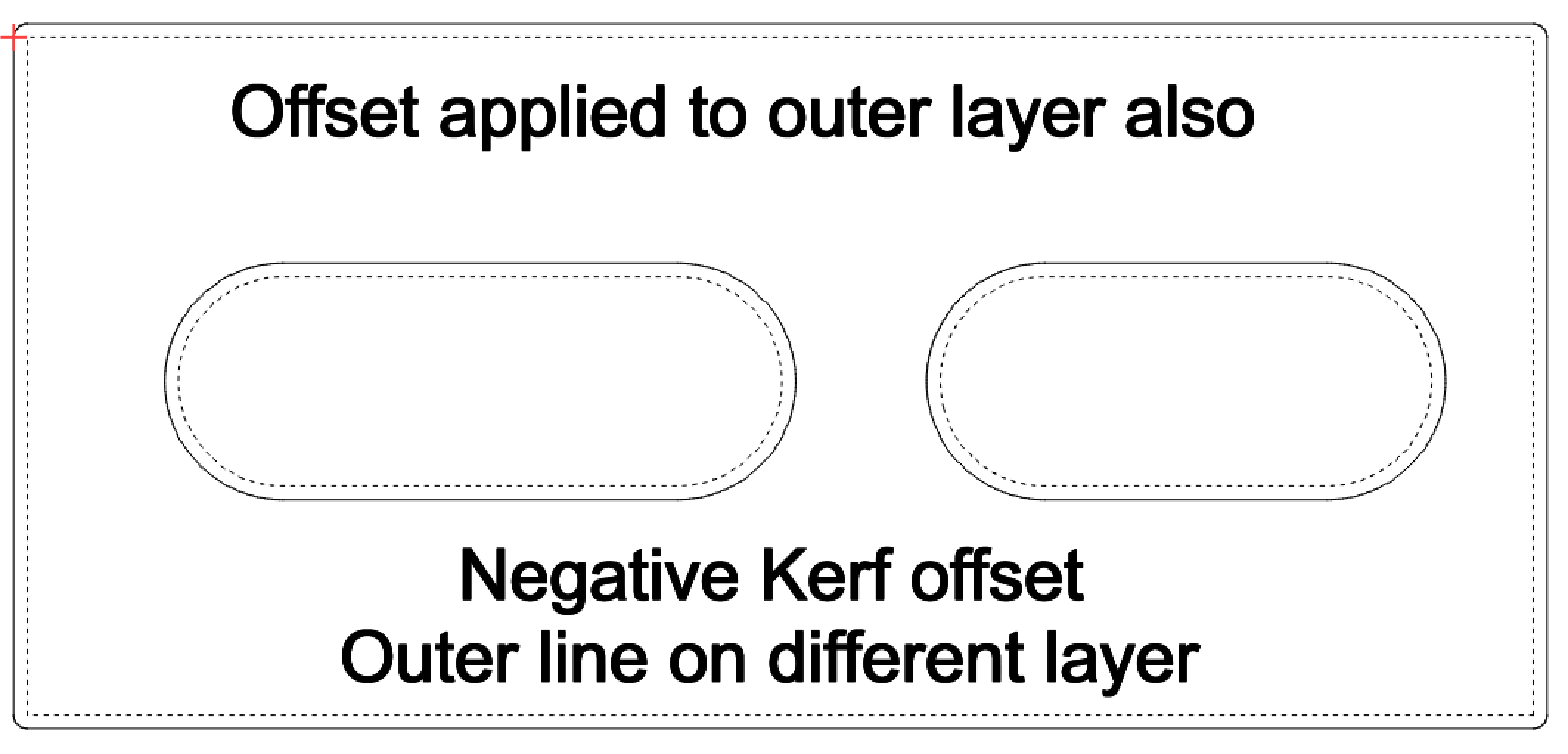
These next 2 are with the outer line on a separate layer and kerf offset applied to the holes, but not the outer line. Notice there is no change to the outer line. It is right on top of the dashed line. Also notice how the behavior of the holes is exactly opposite of how it was with the entire shape having the offset.
These last 2 are with the same offset applied to both inner and outer layers. The outer line is on a separate layer and the same kerf offset has been applied to both layers, but because they are not the same layer the behavior is different than when they were all on one layer.
I hope this helps clear up your understanding of how Lightburn handles this.
Tim, I do thank you for your attention to this. I’ve read all of your responses thoroughly and I do grasp what it is the offset is supposed to do. Philosophically the software is doing just what you say, but the accuracy of the real output is the issue. Take for example, where I say I used the offset of 0.005" which was first determined by using an actual test cut, not theoretical This is using a 1.000" square test piece, measuring 0.990" after cutting with a zero offset (1.000-0.990 = 0.010 / 2 = 0.005). The resultant real world 0.630" slot dimension measures 0.620". Then using the same value but negative, the real world result was 0.640". Neither produce a 0.630" slot. It would seem that LB is doubling the offset value. So why is this occurring?
What dimension do you get without kerf offset applied? With the numbers you’re posting I’m guessing that your laser is cutting .630 natively, which means your calibration is off slightly.
With a .005 offset I would expect a .020 difference between the 2 cuts. It’s .010 negative and .010 positive, which equals .020 difference.
Was the .632 result without any kerf offset applied?
Are you certain that your slot width is exactly .630? Use the measure tool and check by dragging across with your mouse, also check the angle is 0 or 90. Even a 1 degree difference will make a diiference in actual measurement of your slot and may not be noticed. I have been bit by this when using the scale handles, I accidentally rotate something a tiny bit and don’t notice.
I’m not trying to find fault in your work, just trying to find the answer.
Edit: I just redownloaded your svg from above. The dimensions and angles are correct in it.
Edit 2: What material are you working with? I want to experiment on my machine, but different materials react differently.
Your Kerf is actually 0.01, when you draw the box 1" square and it cuts “ON” the line, you loose half your kerf Top and bottom or left and right resulting in 0.990. Your .630 box is enlarging by half top+half bottom resulting in .640, I think the error in your logic is you thought because there a 2 kerfs “opposite each other” you needed to divide by 2. If you measure the cut square it is reduced by half the kerf on opposite sides, and if you measure the hole it left you are measuring the enlarged size by half on opposite sides, so measuring either is giving you a result of original size + or - 1xkerf. It makes sense to me, hope you can follow my description.
If so, then why is the text listed below how laser kerf offset is mentioned when researching this subject…
Reference 1:
Steps to calculate laser kerf
- Cut a square with the laser
- Measure the width of the square with digital calipers
- Subtract the measured width from the original width of the square
- Divide the result by 2
Formula
𝐾𝑒𝑟𝑓=(𝑂𝑟𝑖𝑔𝑖𝑛𝑎𝑙 𝑤𝑖𝑑𝑡ℎ−𝑀𝑒𝑎𝑠𝑢𝑟𝑒𝑑 𝑤𝑖𝑑𝑡ℎ)/2
Reference 2:
Start by cutting a square that is exactly 1 inch with your laser. Measure the square with calipers after cutting to see what the measurements are. To calculate the kerf take the width of the square (1 inch) - width of square measured after cutting=kerf
Keep in mind again that this value equals the full width of the laser beam, but because the laser beam cuts from the center of the cut line only half of the laser beam falls on each side of the cut. Therefore, you will need to divide this number by 2 to get the kerf to add to your design cut lines.
So for example,
1”-.99”=.01” kerf of the laser beam .01”/2 = .005” the kerf of the material for each cut line.