Yes, I have checked and rechecked the design file to be sure. I use parametric design software daily so am well versed in CAD.
This is 1/8" thick clear cast acrylic.
Yes, I have checked and rechecked the design file to be sure. I use parametric design software daily so am well versed in CAD.
This is 1/8" thick clear cast acrylic.
You are correct in your thinking above for how to determine kerf settings.
I ran you file on my machine using 1/4" plywood and learned a few things.
First my Y axis calibration is slightly off. I recalibrated it to my satisfaction.
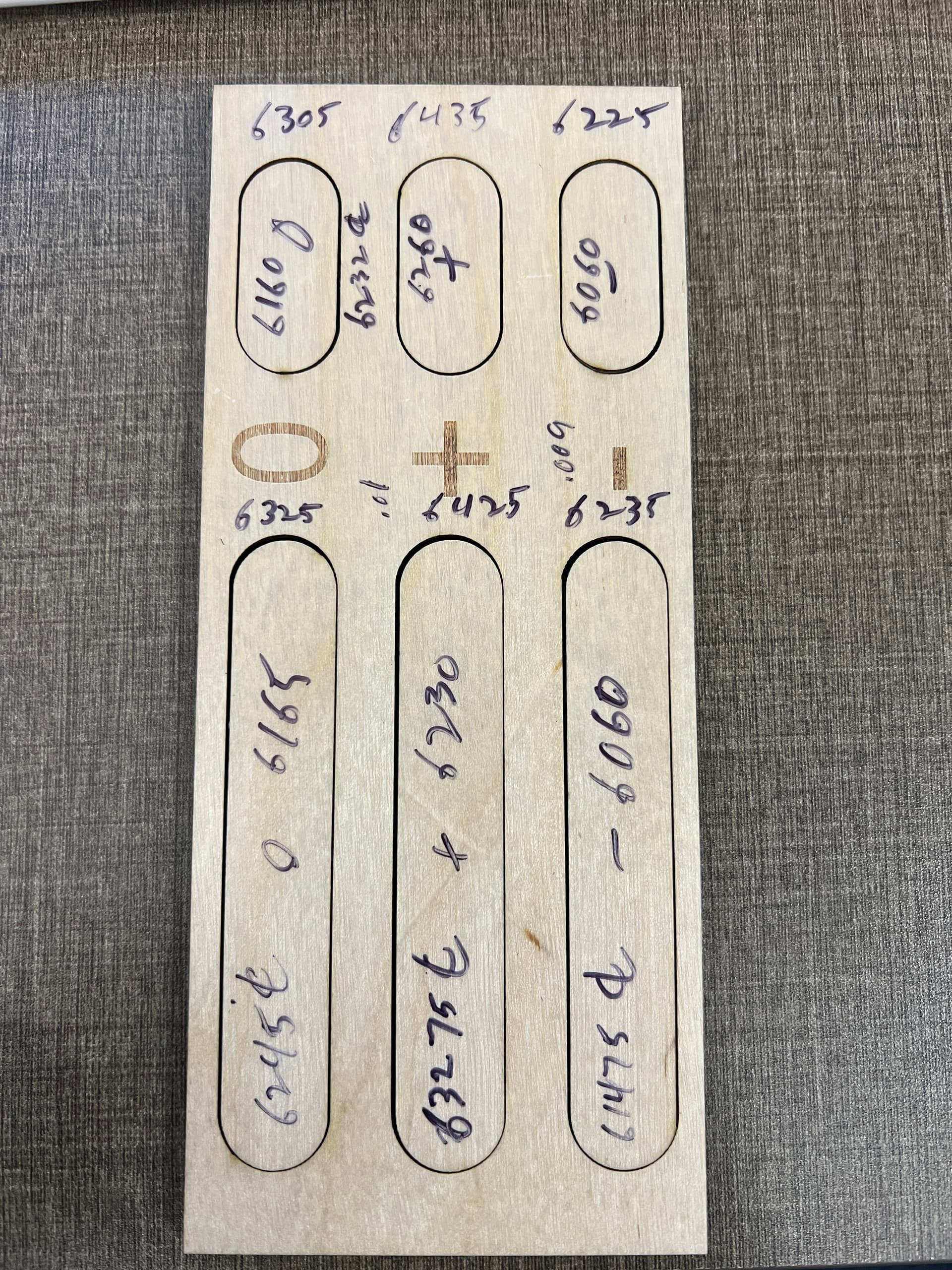
Second, I don’t think it’s possible to get repeatable accuracy to the .001 with a laser, you’re burning / melting material away and that will always have some variation. On my tests I got 1-2 thousandths difference between the short and long slots and there was also variation within a single slot. I don’t know if that’s due to how the material burns or due to slop in my machine.
Here is my test piece with dimensions. I measured the cut and the drop both and split the difference to determine center line. Notice the variation between the small and large slots.
Bottom line, in my opinion, run a test without kerf offset, measure the result and add or subtract the amount of kerf needed to get your desired result, rather than getting hung up on “the numbers say it should be this”, and know that there will be some variation. If you need accuracy to the .001, a laser isn’t the right tool for the job.
Great feedback. Your results largely emulate mine, thus confirming the issue at hand. Based on this, the software is not properly accounting for the kerf as it indicates it does. This is merely a simple math problem with a known solution (Design - Actual / 2). While you may see some variance, a laser is pretty damn precise and asking for +/- 2 or 3 thou does not seem to be asking too much…your results show that. Surely a variance of 0.01" should be unacceptable to most any user of a instrument such as this. While it may not achieve CNC machining accuracy, it is still not unreasonable to expect certain levels of precision.
The Kerf being described here is the kerf of a straight line, not the Kerf of a closed shape, when talking closed shapes you have the kerf with the square twice, once on the top cut for example and once on the bottom so 0.5+0.5=1, In ref 1.3 it is correct IF by original width they mean the hole left in the material the square was cut from, not the drawn square. I think this needs clarification in the documentation. In ref 2 the 3rd last word is critical “EACH” cut line IE: Top AND Bottom - Left AND Right.
Lightburn is offsetting it correctly. If you don’t trust the LB kerf settings, offset your shapes “manually”. If your results are the same, your laser isn’t accurate.
Download @BillieRuben kerf tool and use it… ![]()
Your description should also work.
I have to agree with @RalphU that Lightburn is working correctly. There are a bunch of users that have used and still use keft settings.
I use mm, so the numbers look off to me and I’m too blind/lazy to convert them, however, it seems to me that the kerf on my 3mm acrylic and mdf was surprising larger than expected… I’m still looking for the files after a new computer upgrade.
To see if it’s following the drawn line, you need a kerf setting the same size as your lasers kerf.
Good luck
![]()
The focused beam is vaporizing 18 mm³/s of plastic and blowing smokin’ hot gas through a 0.2 mm slot with a 15:1 aspect ratio, so ±2 mil = ±0.05 mm of accuracy along the side walls seems way smaller than the process allows.
Even though the motors in my machine take 0.012 mm steps, the motion definitely lacks such resolution! ![]()
Yep, thats why I don’t use a single cut/shape to work out Kerf, I use a design with multiple cuts then divide total kerf by number of cut to get a better average.
It all sounds very complicated without it needing to be.
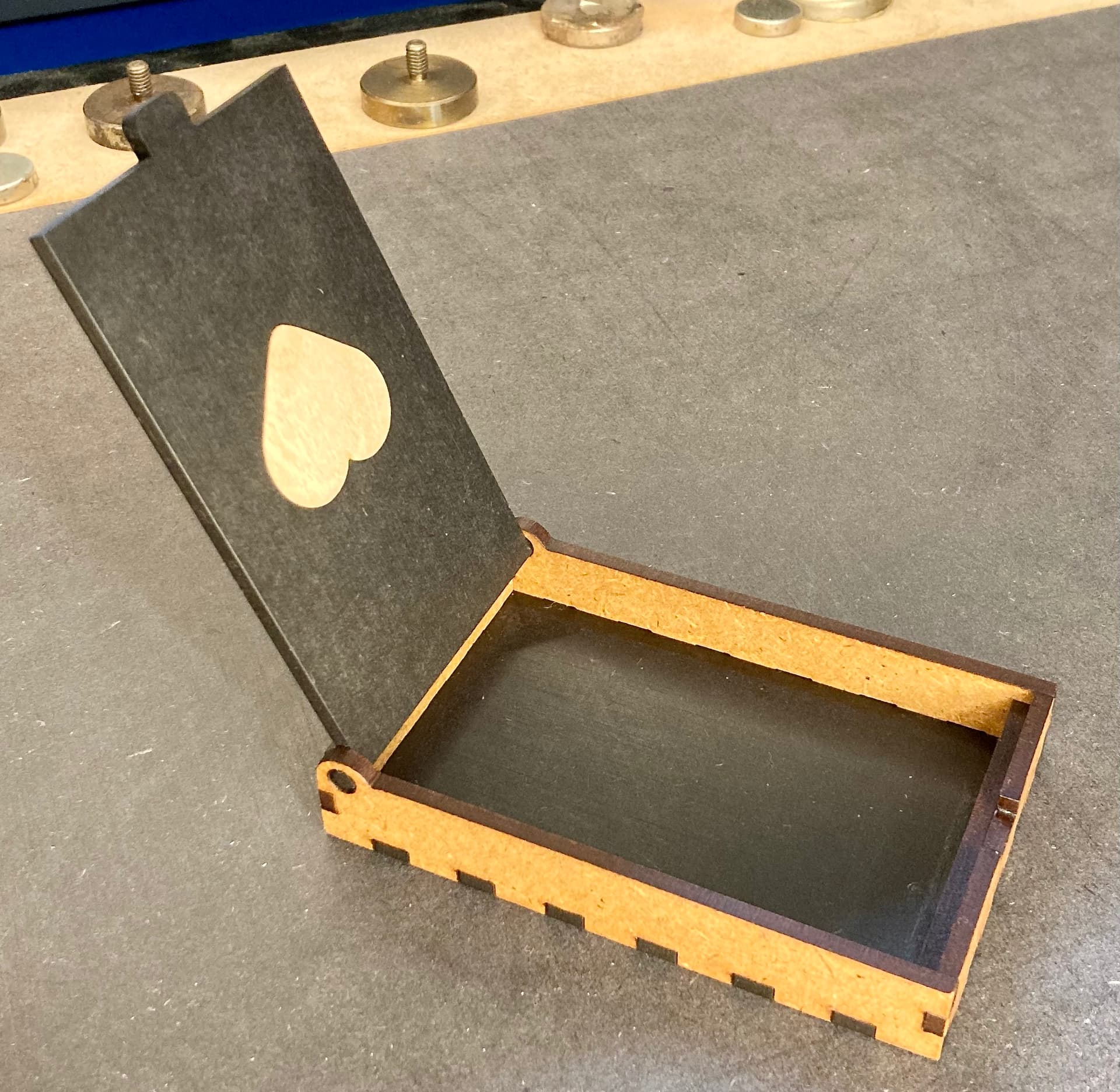
Take a very simple example. In the small box the heart is cut in the black lid. Out of light material I have cut another heart, all settings (including my finger joints) are cut with 0.075mm kerf and constructed with total dimension “0”, i.e. 3mm is 3mm and not 3.xxx mm or 2.xxx. This gives a tight press fit in MDF and hard birch plywood.
LightBurn subtracts and adds on the “male and female” parts and figures it out for itself.
Of course you can cut without kerf and assign an offset to one of the parts or both, but why make it more complicated as necessary when there is a kerf function.
Another phrase I have fallen over is “offset of a single line…” or similar, you cannot add or subtract kerf from a non-closed shape. When my press fits once do not fit, it is because I have not checked whether the shapes are closed and they are open.
This topic was automatically closed 30 days after the last reply. New replies are no longer allowed.