Brilliant. Thanks so much for sorting this out for me. It’s another thing ticked off.
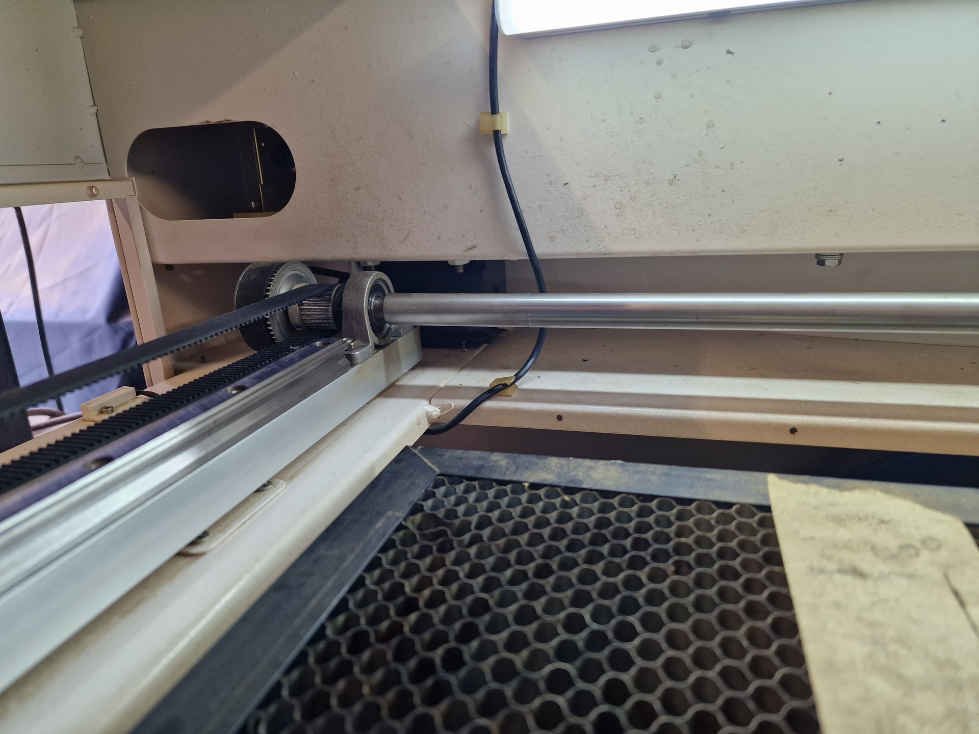
Do you know if It is possible to adjust those rail guides? They seem very tight. Just wondering if adjustments might help?
Brilliant. Thanks so much for sorting this out for me. It’s another thing ticked off.
Do you know if It is possible to adjust those rail guides? They seem very tight. Just wondering if adjustments might help?
The linear bearings will (should) be snug in all directions and slide smoothly in the obvious direction, with no adjustments possible. You must (should) disconnect the belts to get them and the motor out of the test, but don’t bother for the first test. With the power off the gantry should push slowly & smoothly across its full range of travel. If it jams or sticks anywhere, that’s a problem.
Stepper motors generate torque proportional to their winding current, as determined by switches on the drivers. In principle, those switches will be set correctly in the factory / by the seller and never need any attention, but it is possible for them to be incorrectly set; @jkwilborn had drivers arrive set for about twice the motor’s rated current.
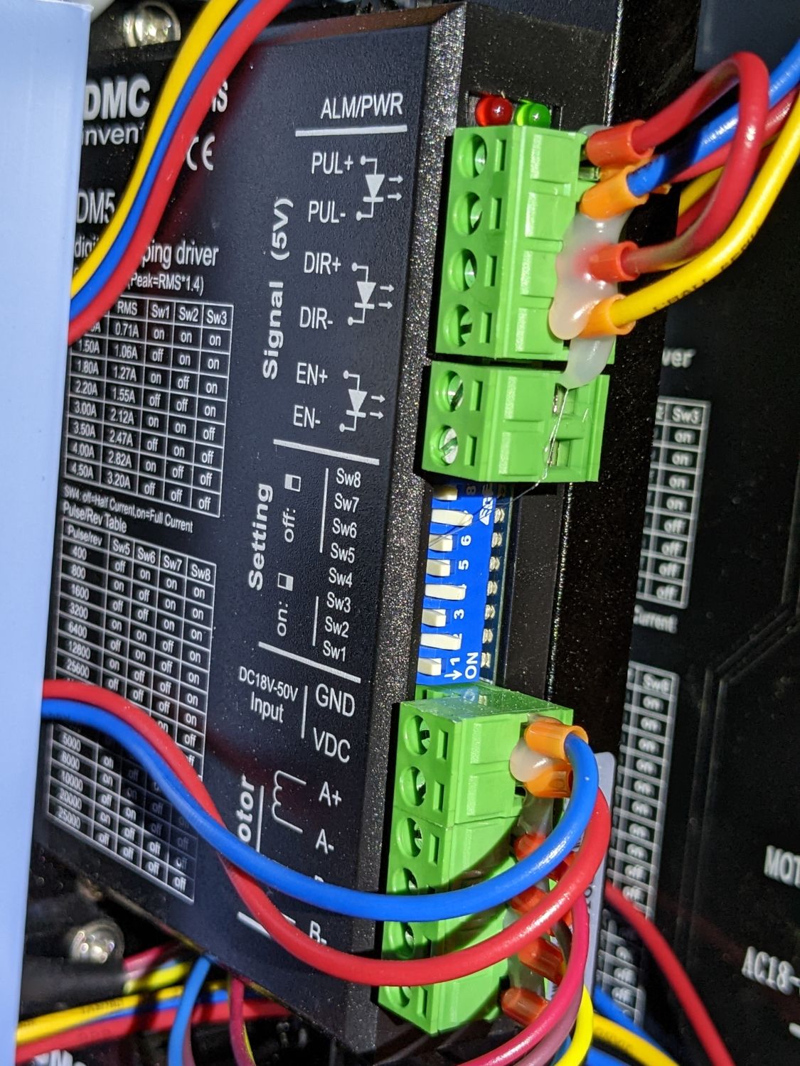
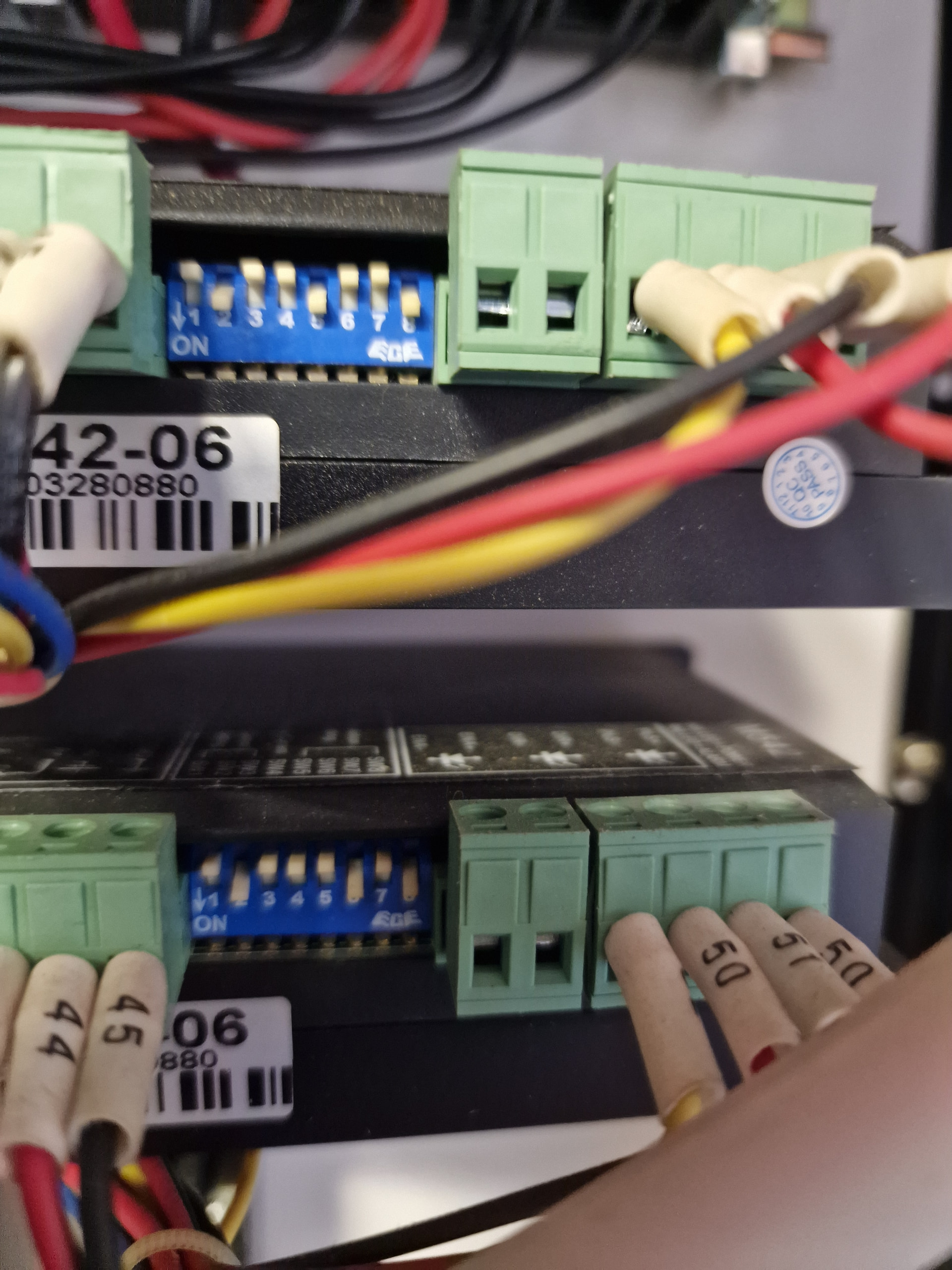
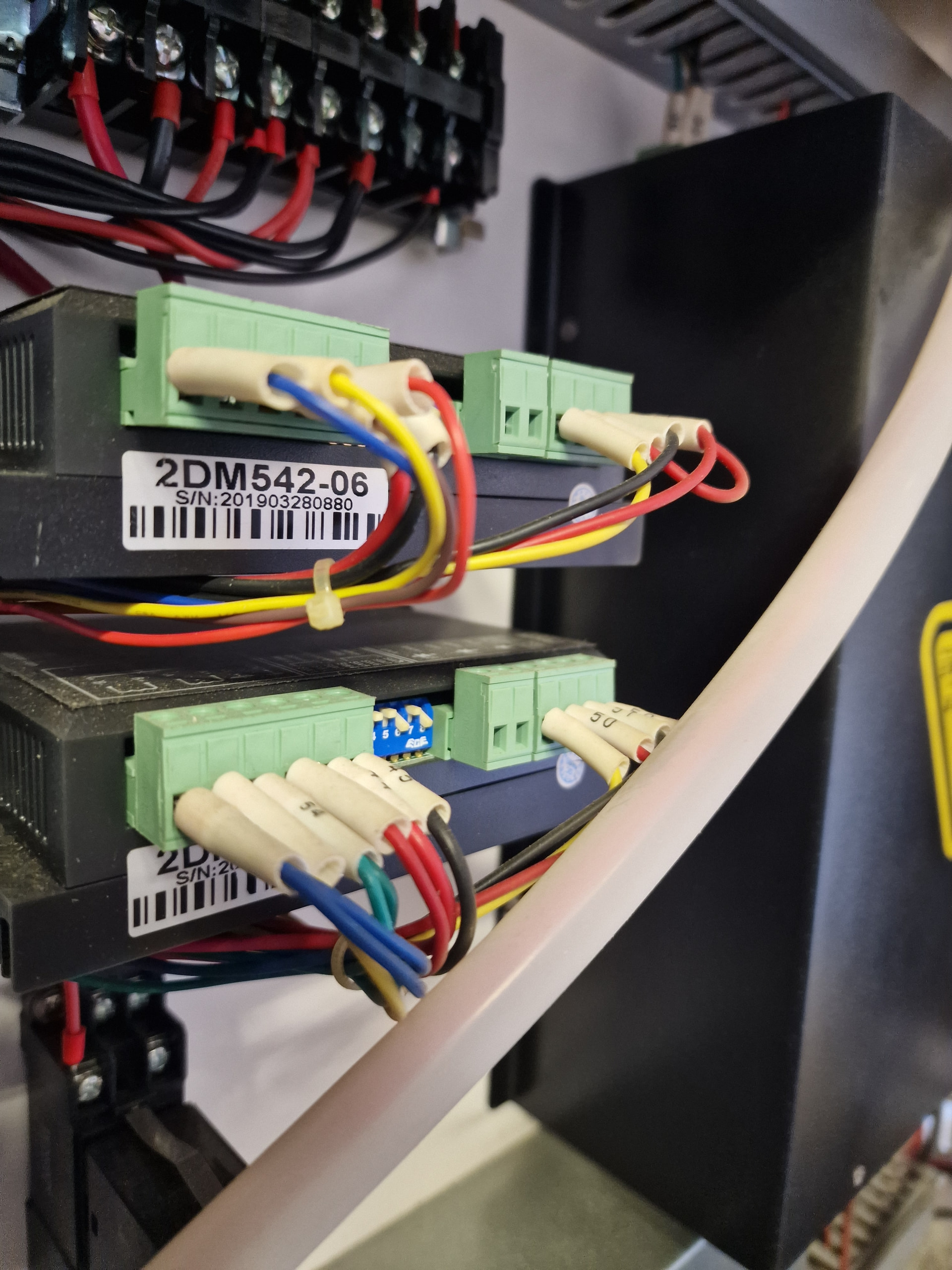
To eliminate the possibility the Y axis driver is set for too-little current, get good pictures of the switch settings and the (barely visible) data plate on the side of the driver so we can ponder them:
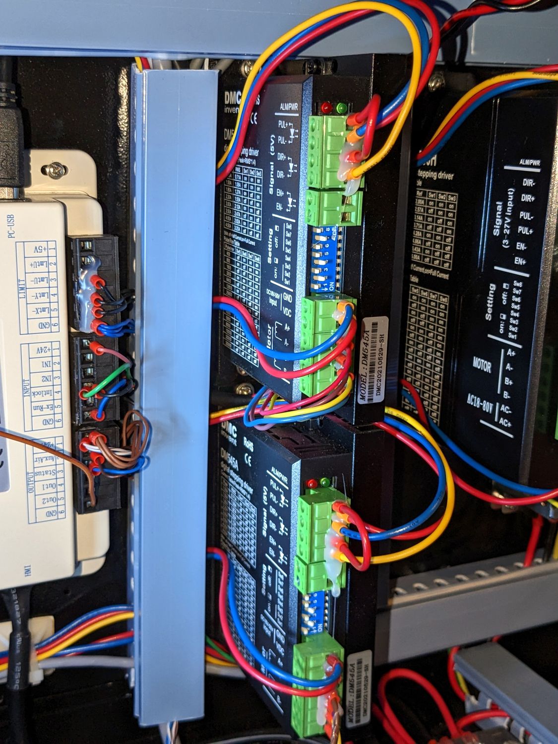
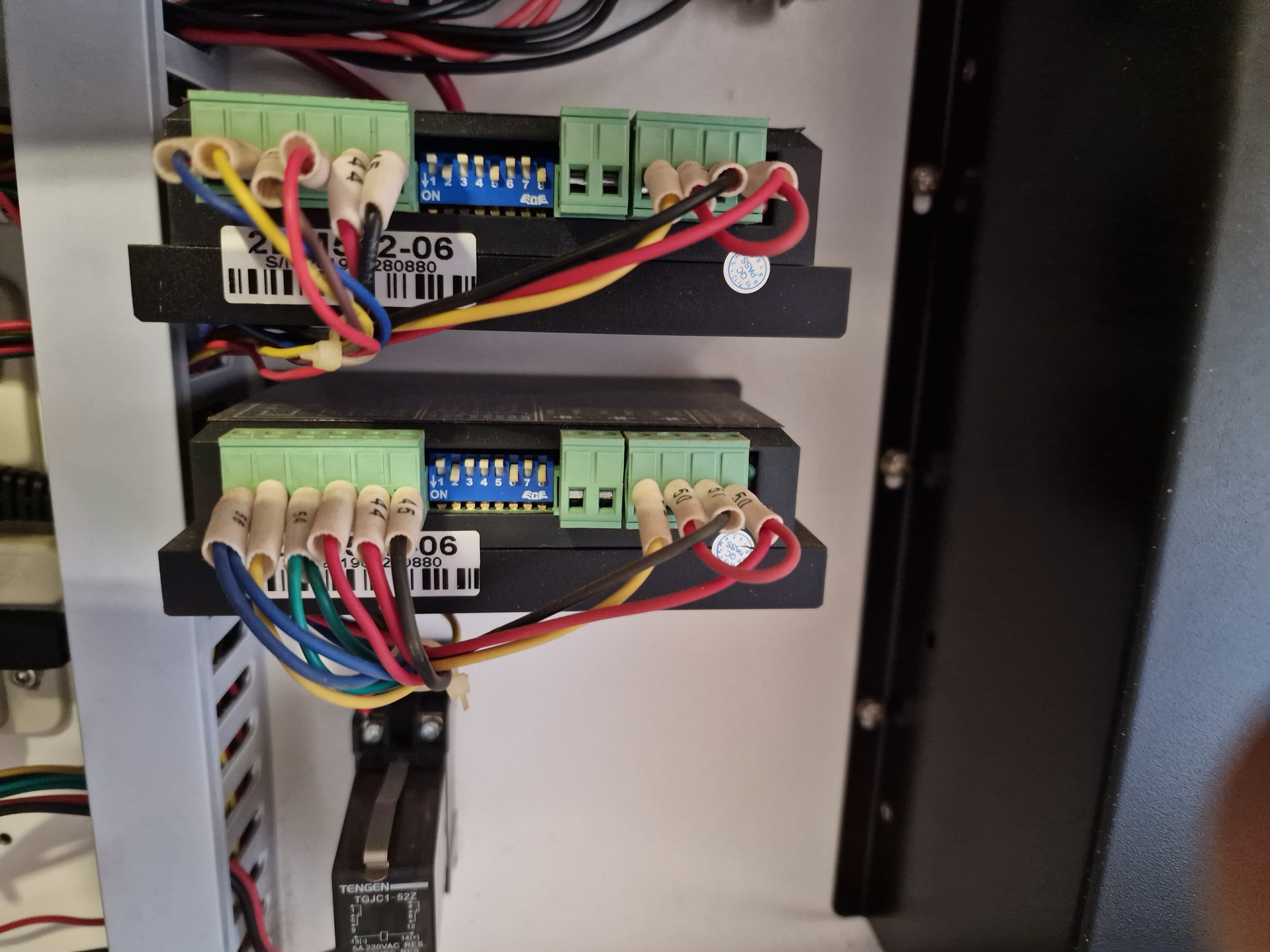
The X and Y drivers are typically the same, because the motors are typically identical, so you can compare the two driver settings:
The Z axis motor, if it has one, and its driver will be different.
I’m still thinking mechanical trouble …
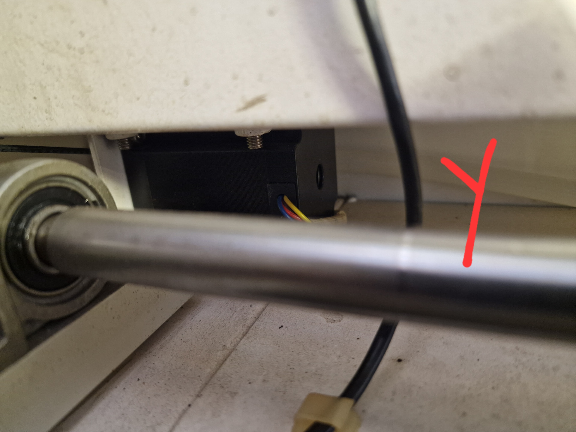
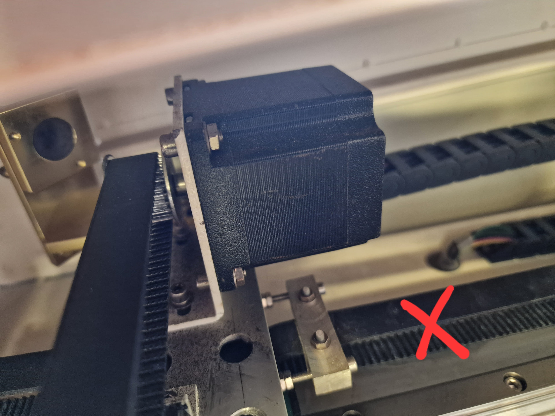
Grub screw on the y motor .
Loosen it , take it off ,set it back onto place with the flat perpendicular to the grub screw .
This has driven me nuts when first building.
Now that would be a nightmare. Not sure who designs these things but access is rediculous.
I cannot find anything that is loose or moves anywhere. I’ve taken some videos of the belt tightness and y movement for feedback it says i can’t post videos.
SW4-8 set the number of steps per motor revolution, so those will depend on the pulley sizes. The two settings look like:
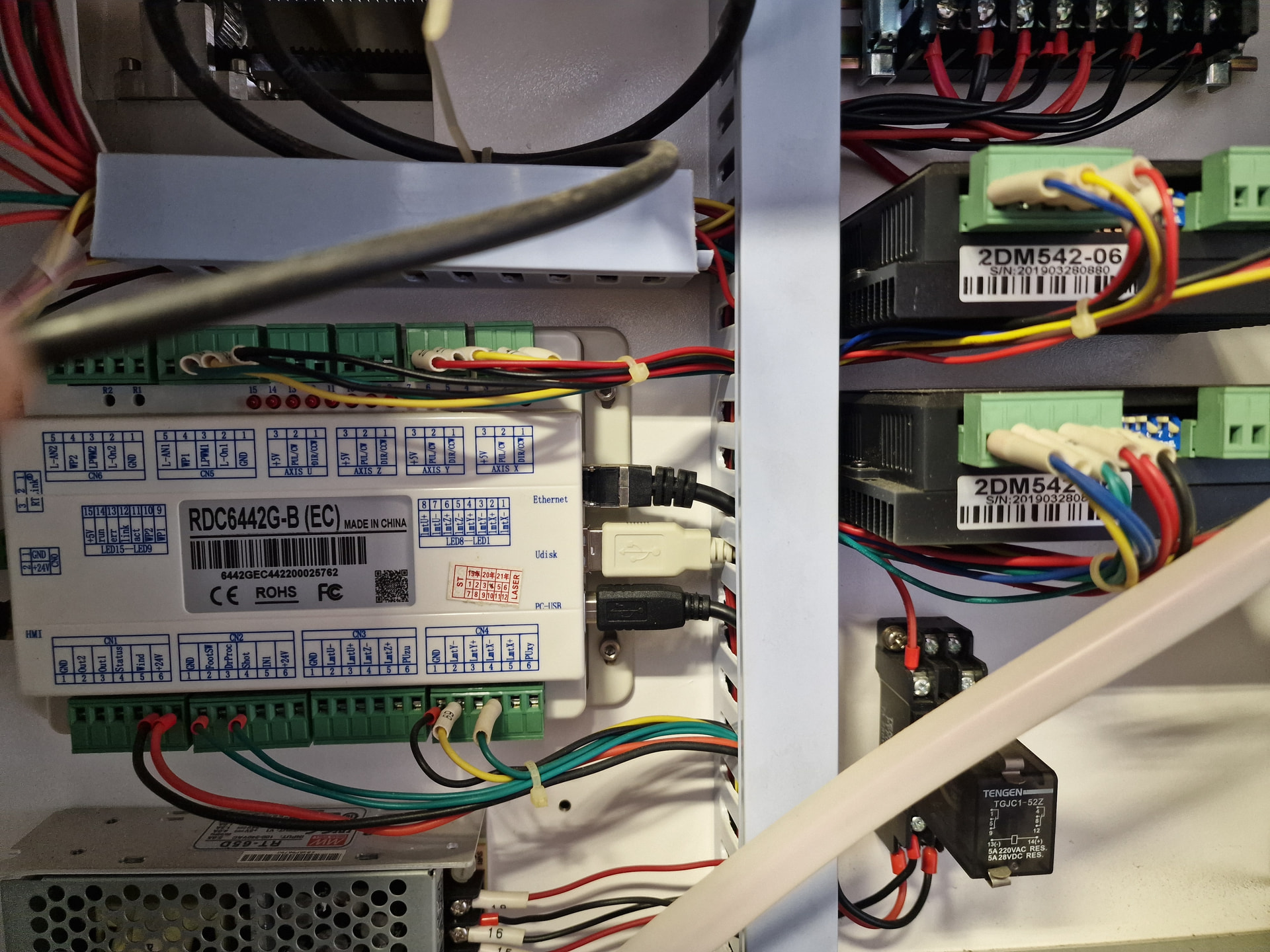
The only way to know which is X and which is Y is by tracing the wires from the controller through the raceway to the drivers.
The empty U and Z terminal blocks show the machine does not have a stepper driving the platform up & down. It may have a DC or AC motor with a pair of pushbuttons on the machine.
FTFY: “I have not yet found anything that is loose or moves anywhere.” 
A mechanical problem is not absolutely certain, but based on what you’ve reported we’ve ruled out a host of other common causes.
Until you have loosened / wiggled / tightened every [mumble] setscrew along the Y axis drive train, then the loose one remains to be found.
The good backlash test rules out a sloppy-loose setscrew, so it’s likely jammed against one side of its shaft flat, where it will remain until the motor moves just right to twist it free and jam it against the other side of the flat, where it will stay until the next just right motIon occurs in the other direction.
Wiggle all you want without loosening the screw and you’ll never feel it, because your fingers cannot apply the just right torque / acceleration / motion to the shaft, especially in a place you can barely see.
Understood…job for another time for now. Thanks for your help.
This is most likely the Y-axis, since X has no gear reduction so would need more microsteps to get resolution, also this driver has two sets of motor wires, so I’m guessing there is another Y-motor on the other side and it looks like they could be hard-coupled together with that shaft?
It would be useful to see the specs of the Y-motors to check their current rating, because the current dip switches look to be set the same as X, but if there are two motors the same as the X motor at half-current then step loss under load would be unsurprising.
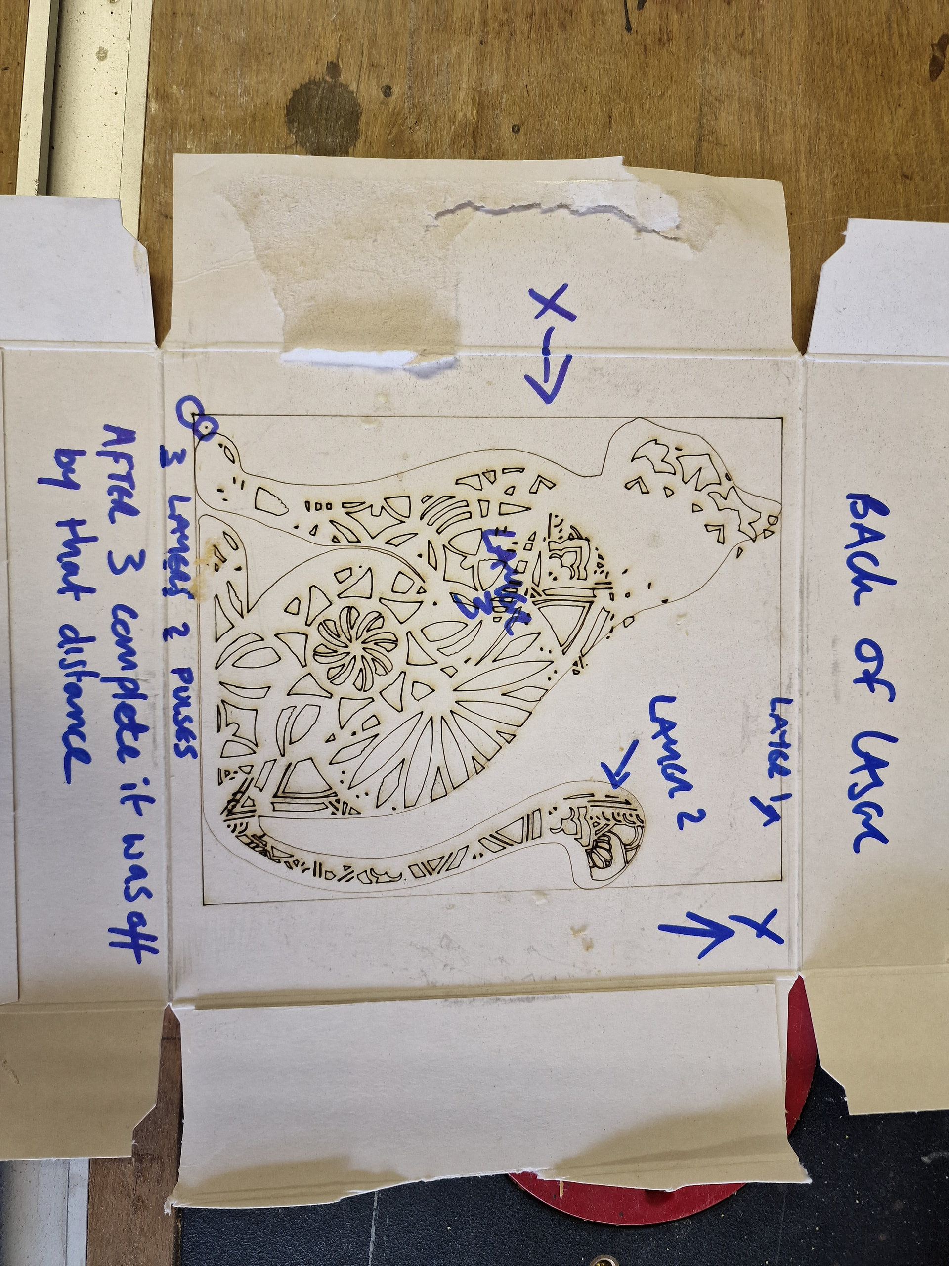
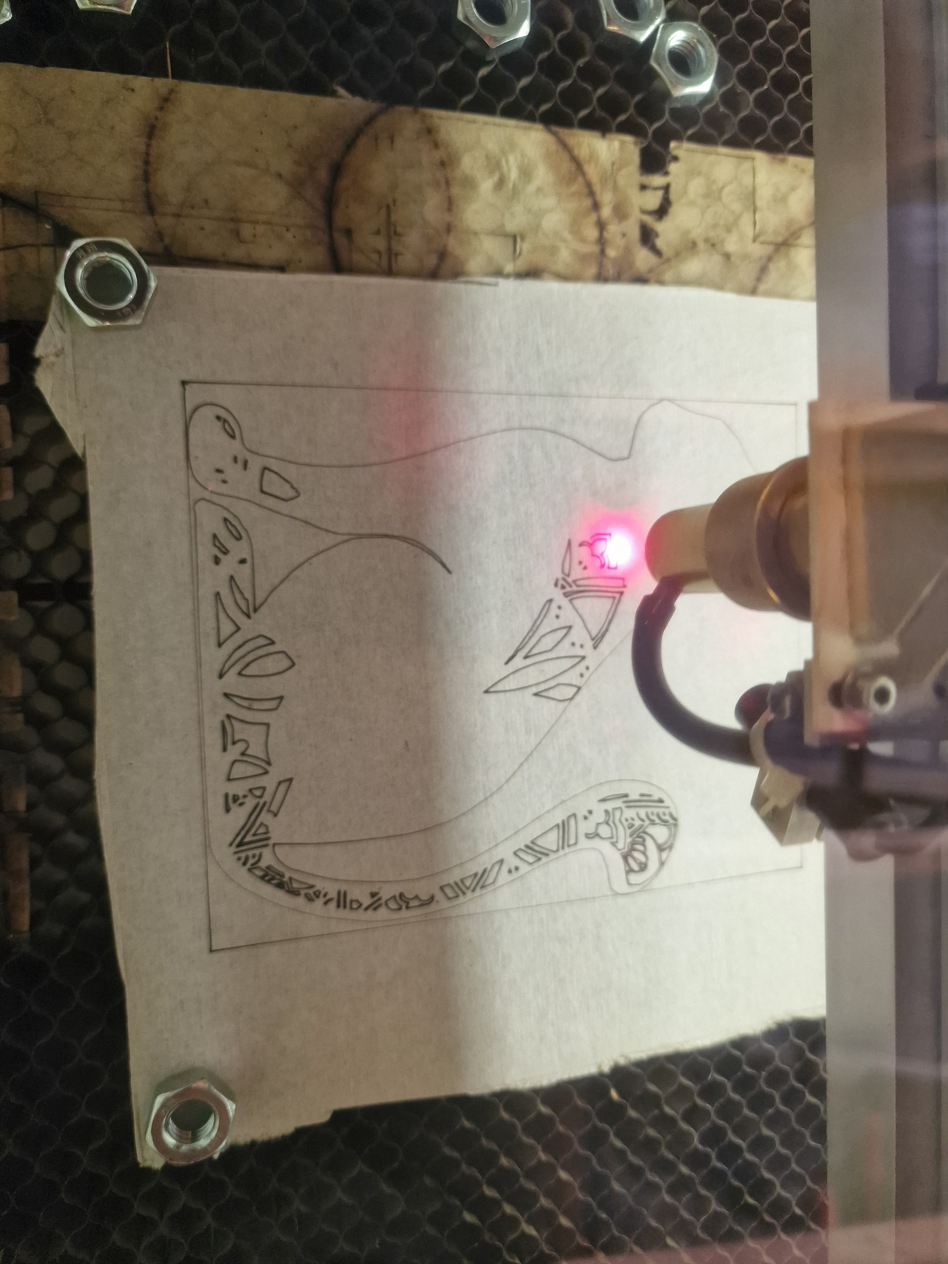
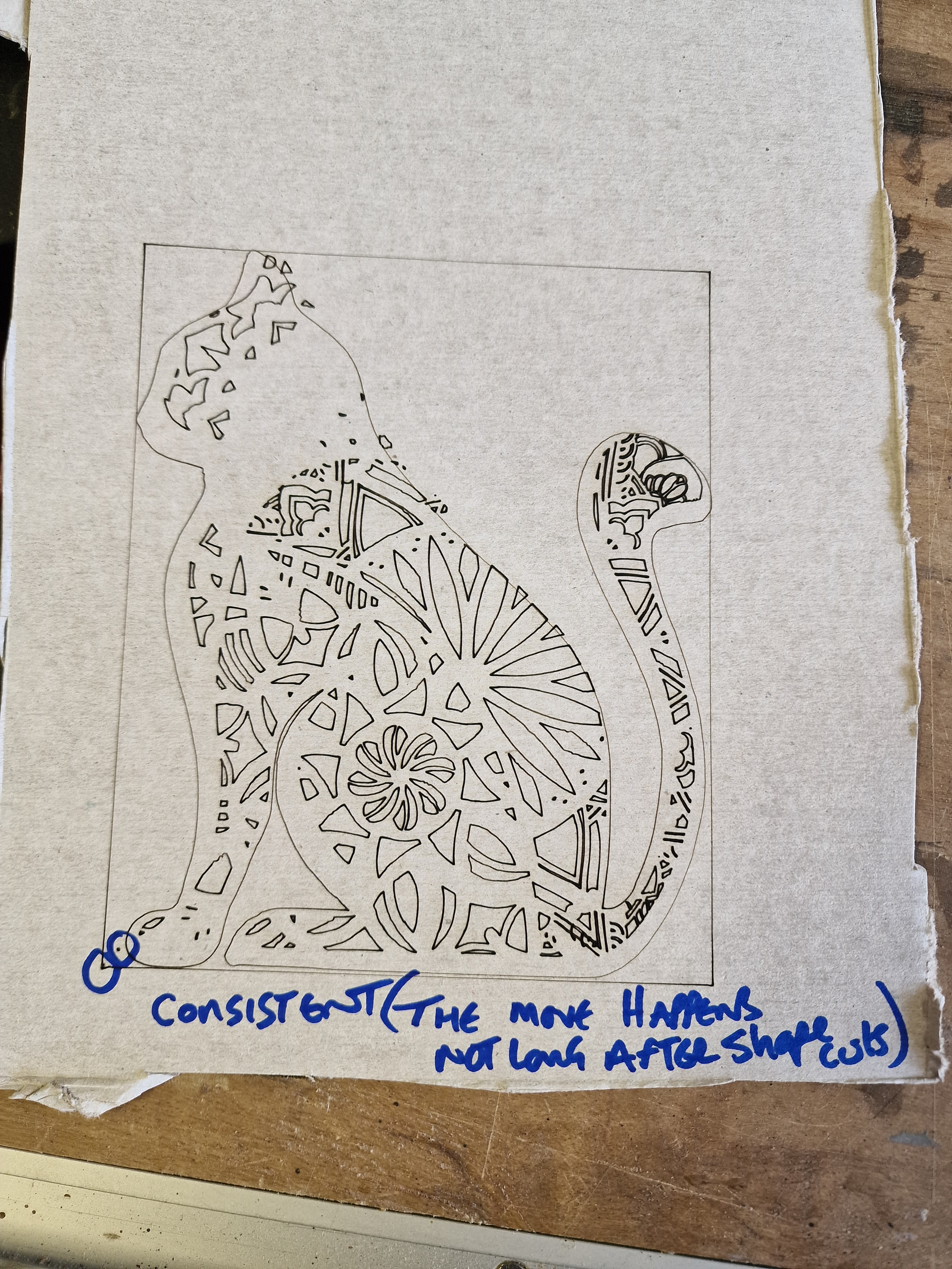
The origin does not change after box or outline layer but after shape layer its out. Going to try a different shape layer for giggles!
Yes for rotary.
Ok thanks, it makes better sense that the stepper driver would be at the same current setting then, although it would be good of that Y axis motor had a readable spec plate to check it’s current requirements. Is there not a pass-through panel at the back where the motor is that can be removed?
That’s unsurprising, because simple patterns don’t have the exact motions required to knock the motors / hardware awry. Right now, the cat’s interior is the definitive testcase: it always fails, which means you’ll know when you find the problem.
That’s important new news: the problem affects both axes.
The stepper drivers have two LEDs to the right of the terminal block from the controller:
In normal operation the green LED should be steady and the red LED should be off. Is that what you see while running the cat interior?
The stepper driver data plate shows the power supply range is 24 to 50 VDC. The Ruida 6442 data plate shows the usual 24 VDC power input and the manual says “compatible with 36V for power supply, but not recommended”.
I’d lay big money saying the machine has a single 24 VDC power supply for both the steppers and the Ruida controller. That would be at the lower limit for the steppers (which are having problems) and at the upper limit for the controller (which would develop heartburn).
Having eliminated all the other problems, I put further money saying the power supply is failing. They’re typically under-sized for the machine’s total current and seem to fail early.
I’d expect the voltage to be about 24 VDC while the machine is idling and a bit lower when it’s running. Without an oscilloscope it’ll be almost impossible to catch a glitch in action, but the LEDs on the stepper drivers may flicker to indicate a brownout.
At this point I suggest preemptively replacing the power supply with one rated for 15 A or so:
That adds up to 10 A. A 50% margIn seems prudent given that the stepper drivers are at the low end of their range.
Side bet: The OEM power supply will be rated for maybe 5 A, definitely less than 10 A.
Protip: Get the power supply from a reputable seller who does not also offer skimpy beach attire, pet food bowls, and acupuncture needles …
Well I’ve got an interesting addition to your thoughts.
I replaced the tube after it blew a few weeks ago. After firing it up I noticed that the internal light wasn’t turning on and figured the tube had blown. However, I now know it’s a 220v led strip which is wired to an internal power source. I purchased a replacement to find it didn’t light up either. I removed the old light and powered it from the mains. Both old and new lights worked as intended…however, the other day I was working on it late and realised that the Old light was turning on but at about 5% and nearly visible. I’m wondering if you are right and that the power supply/s are damaged.