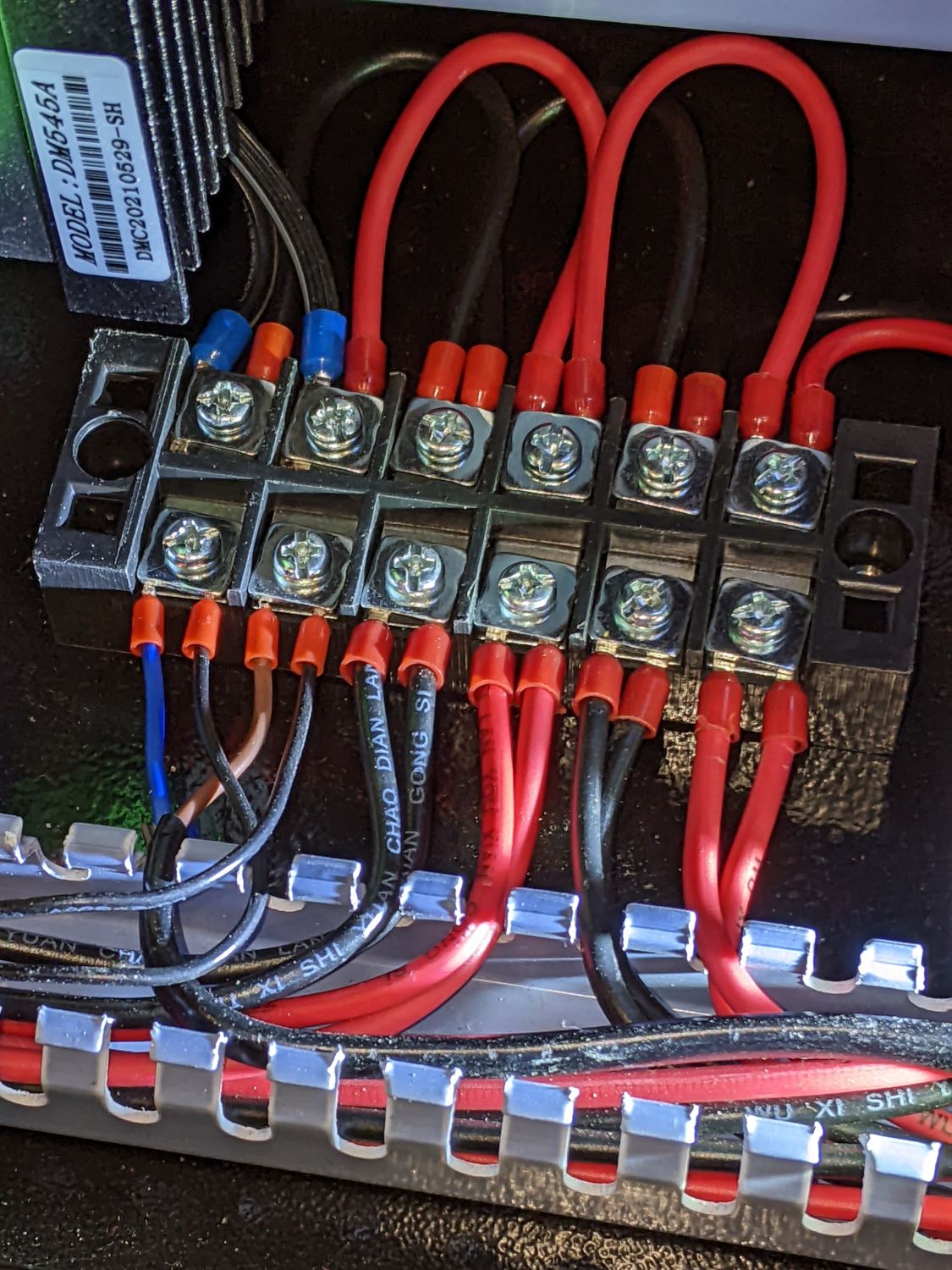
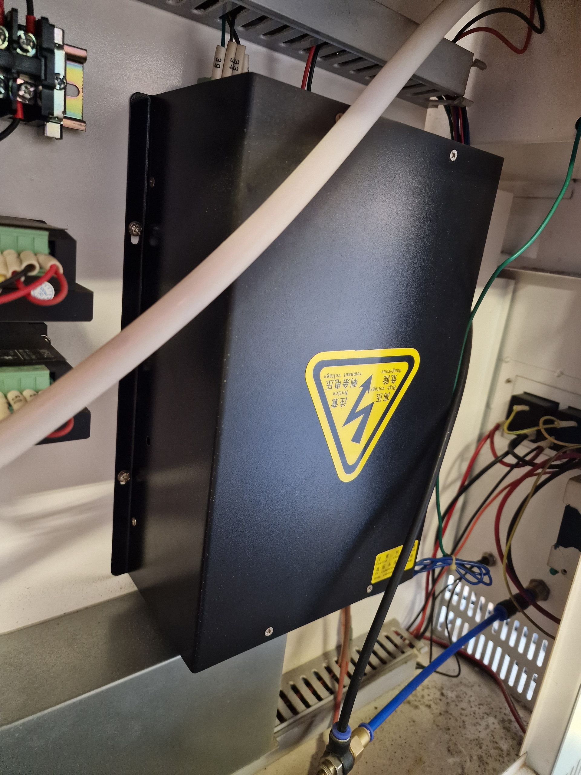
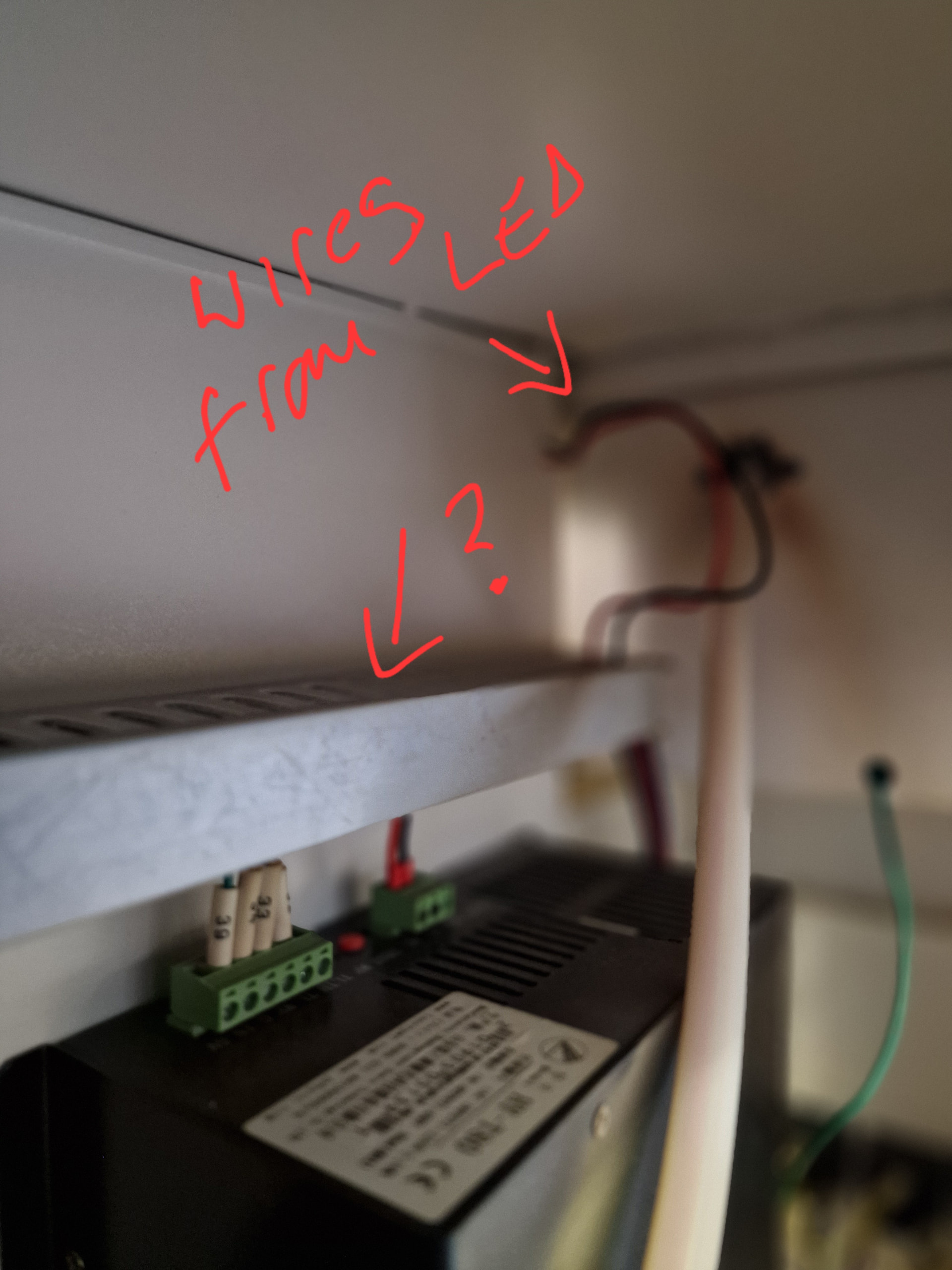
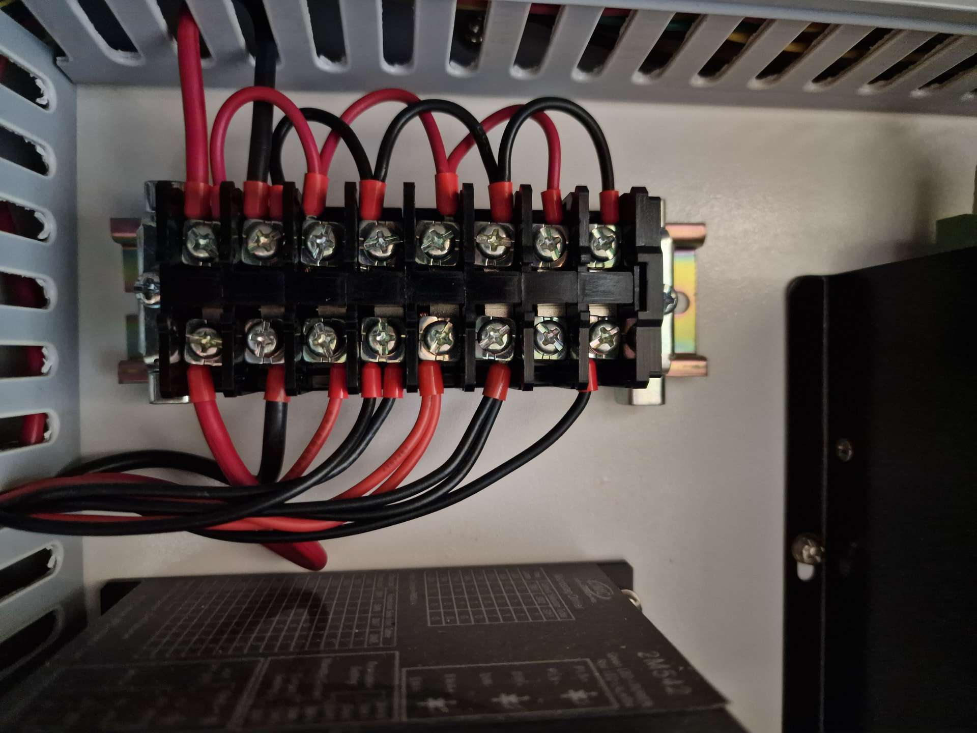
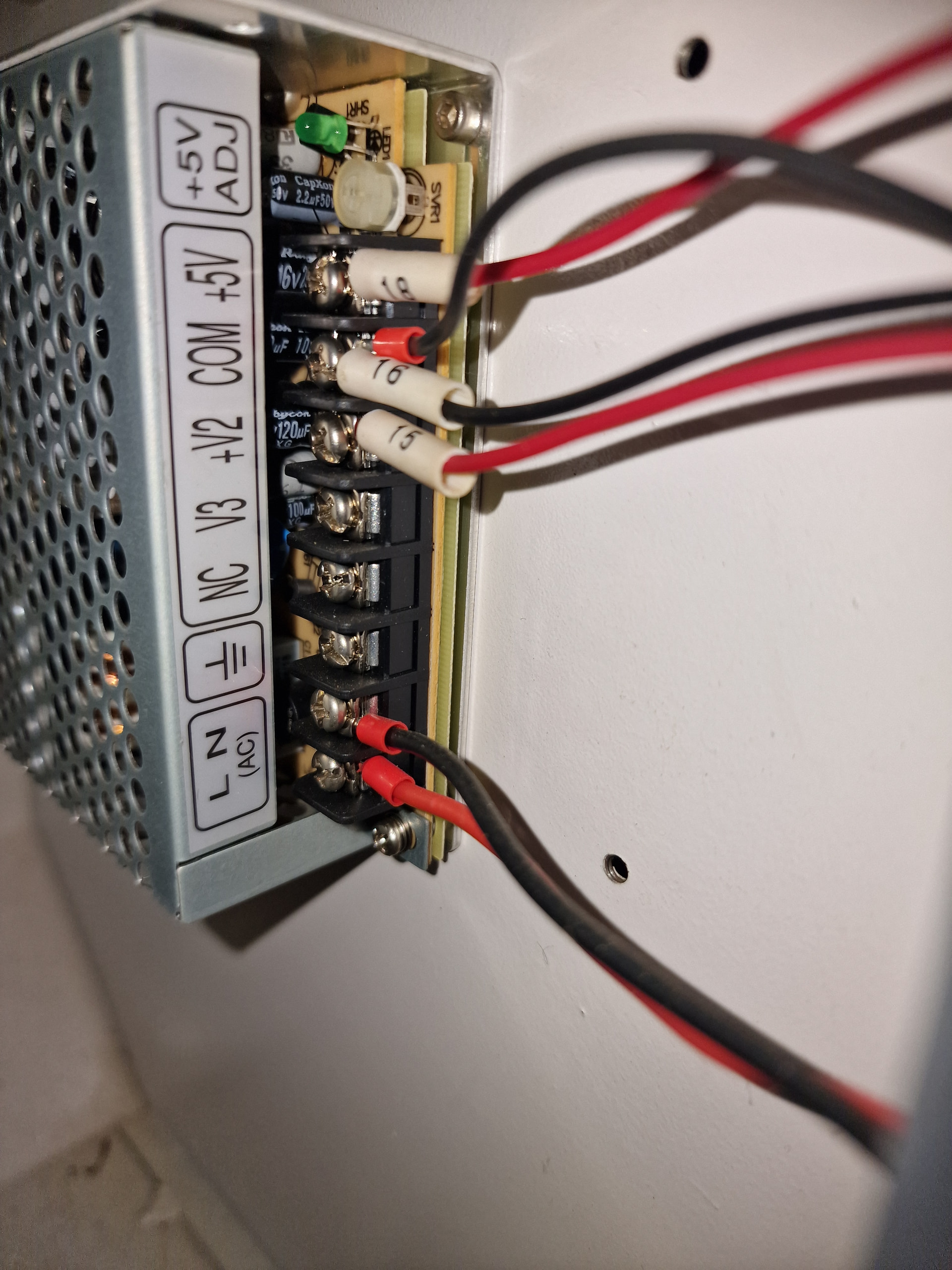
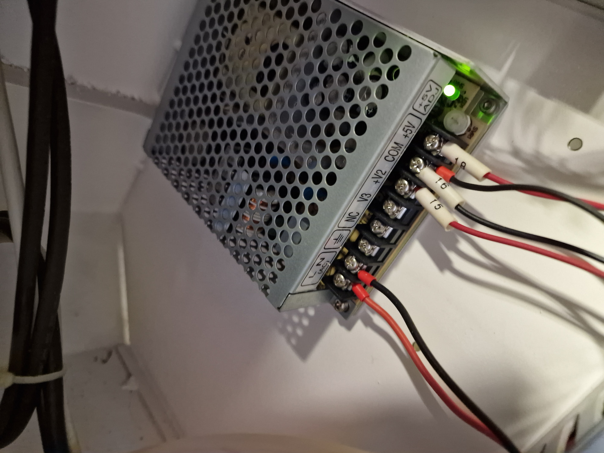
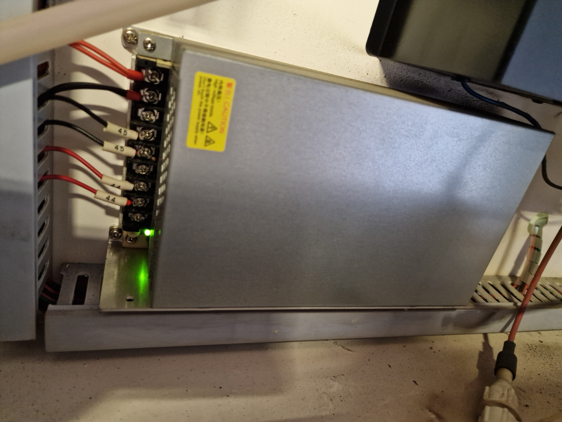
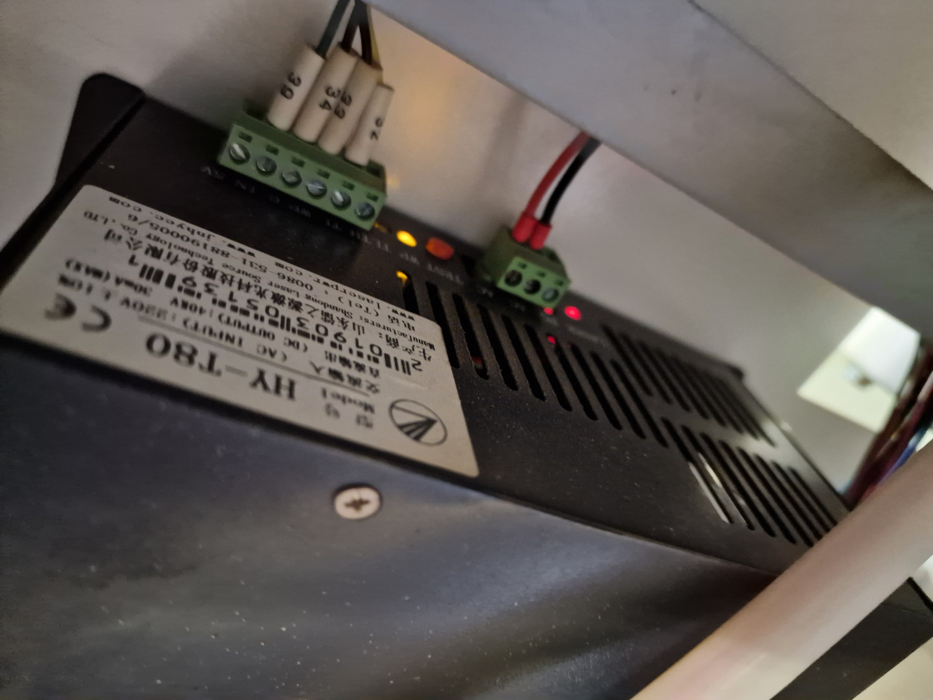
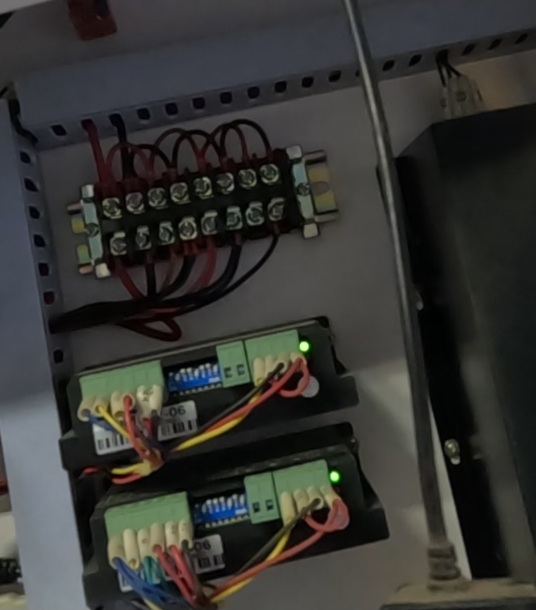
It’s not clear what the LEDs are connected to, but it’s possible a screw in the barrier strip distributing the wall-socket voltage (“220 V” is definitely not USA-ian) has come loose and the input power to the supply is glitching.
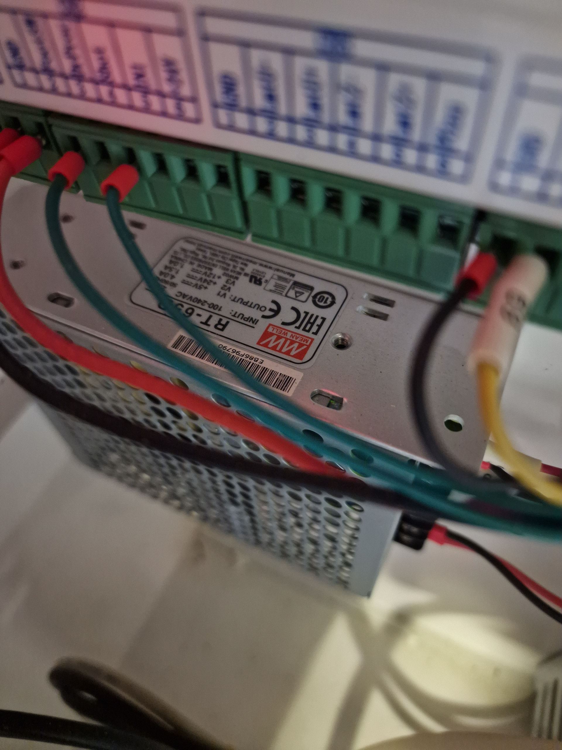
Find the sticker on that power supply with its ratings so we know what’s going on. If the sticker isn’t on the end with the terminal strip, then it’s on the bottom where you can’t see it.
Assuming the input power distribution block (and all the wiring) passes inspection, that’s the supply to replace.
FWIW, having two low-voltage supplies (one with three outputs!) is exceedingly unusual. That’s far
more attention to detail than you’ll see in the current crop of imports.
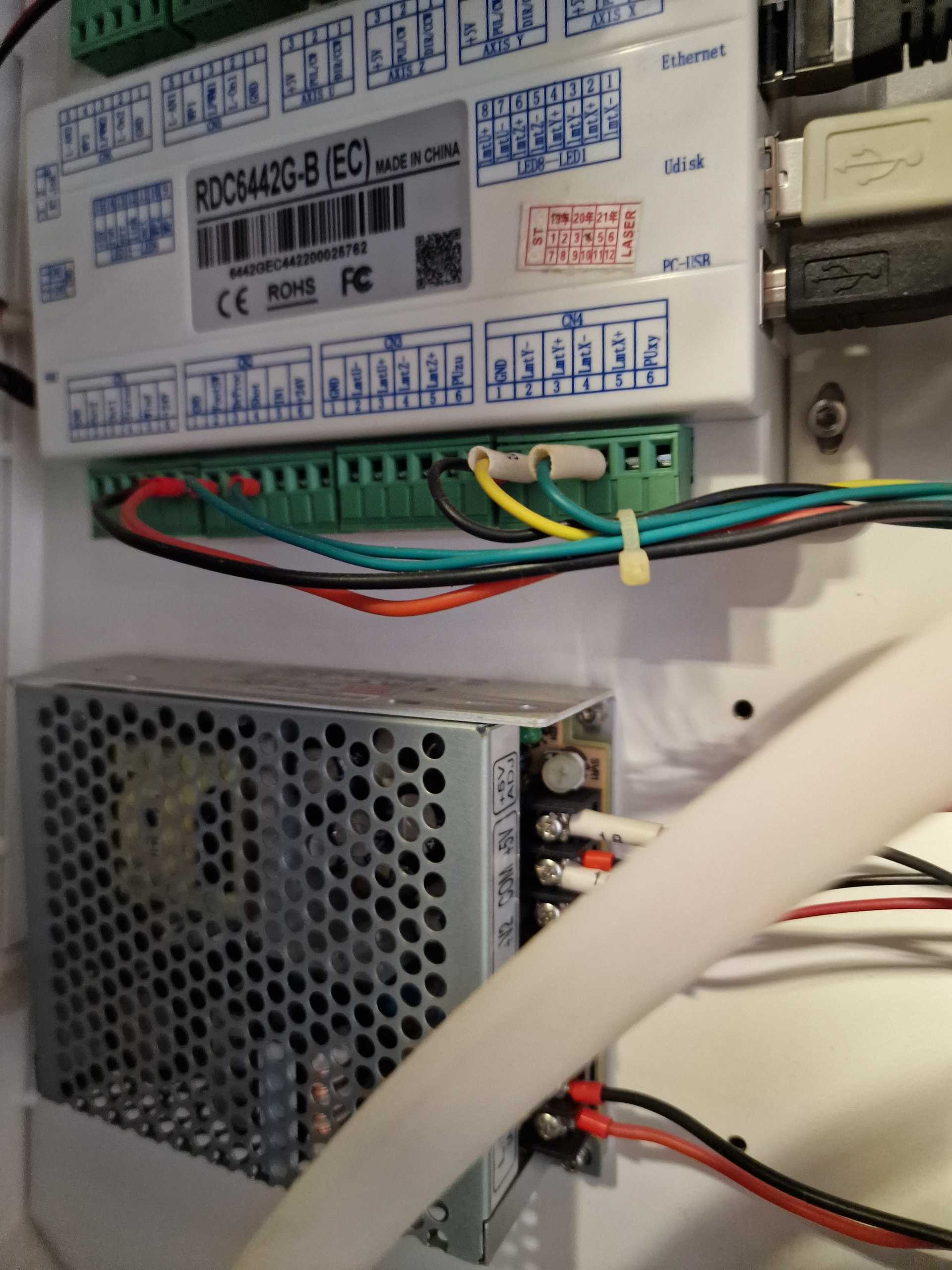
+5, +12, and maybe +24 = perforated silver case directly under the Ruida controller
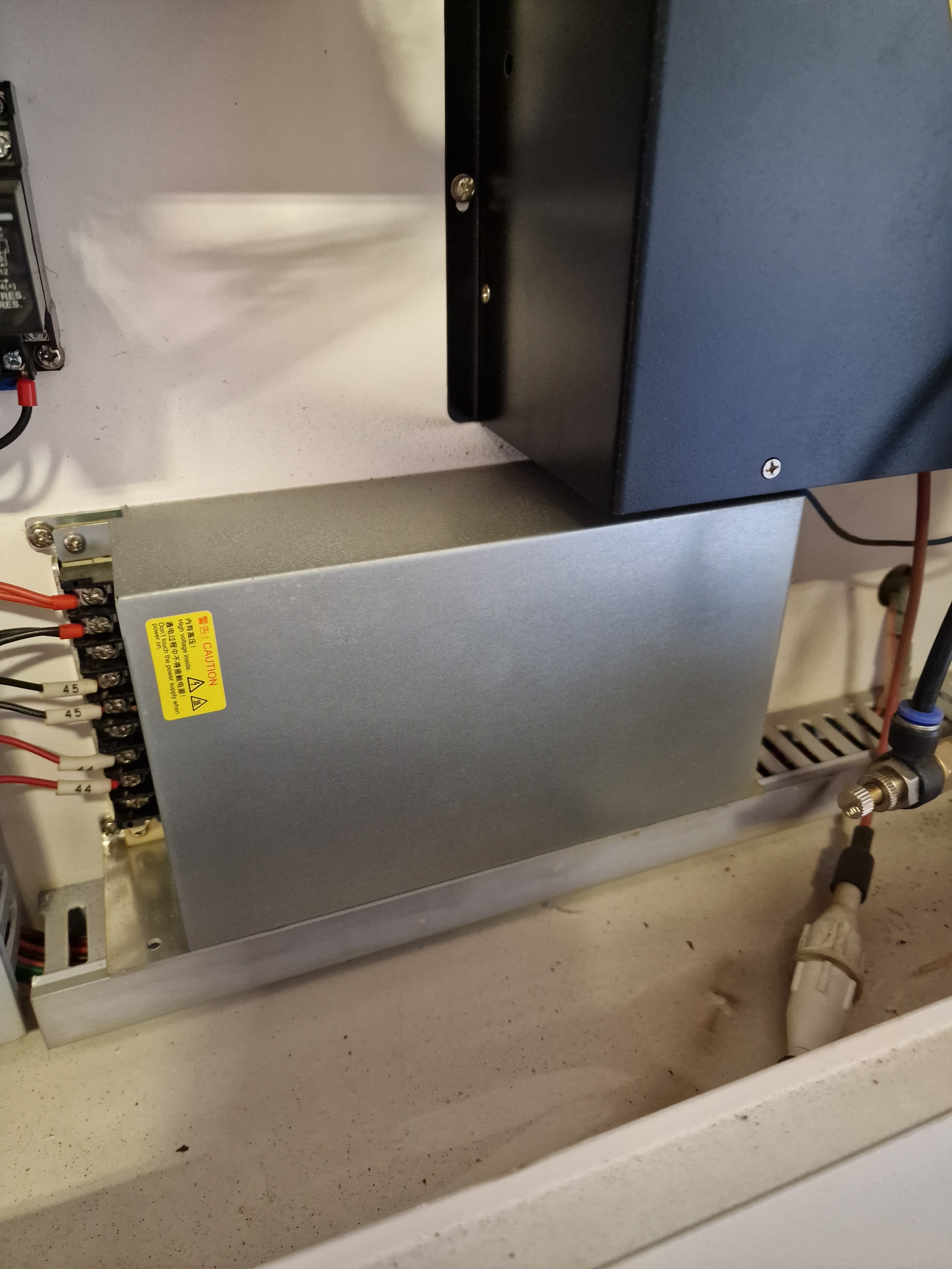
+36 = solid silver (?) directly under the black HV supply
Extra-spicy HV laser supply = large black case with the fat red HV wire out the bottom
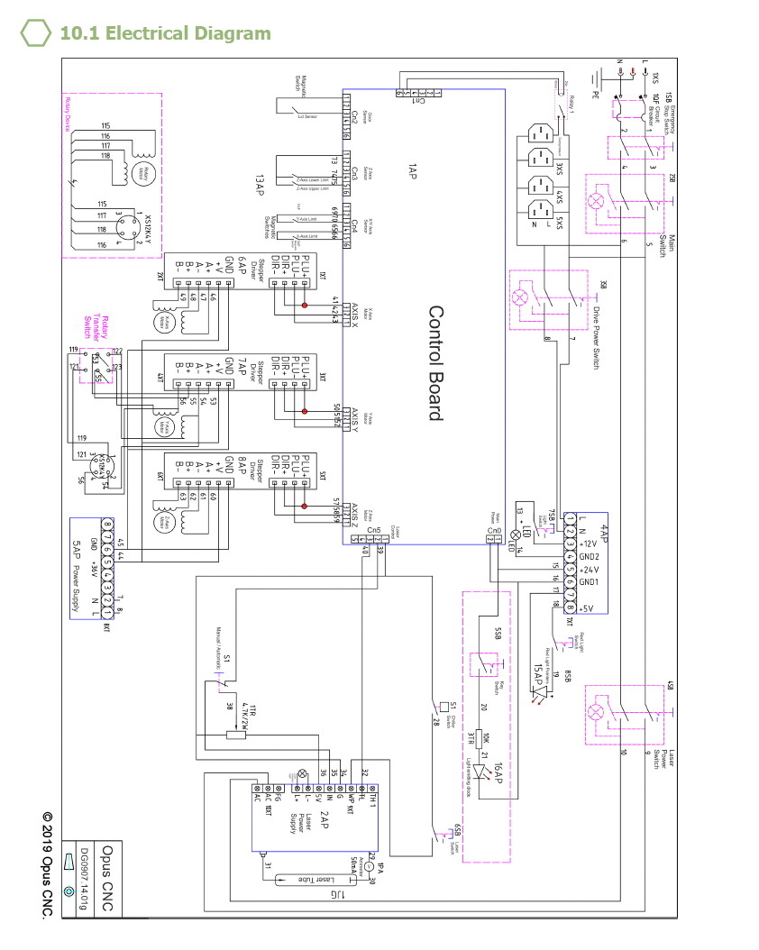
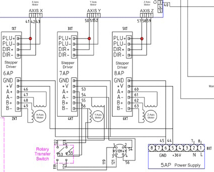
The wires on the 36 V supply have tags 44 and 55, which match the wiring diagram, and those tags reappear at the stepper drivers.
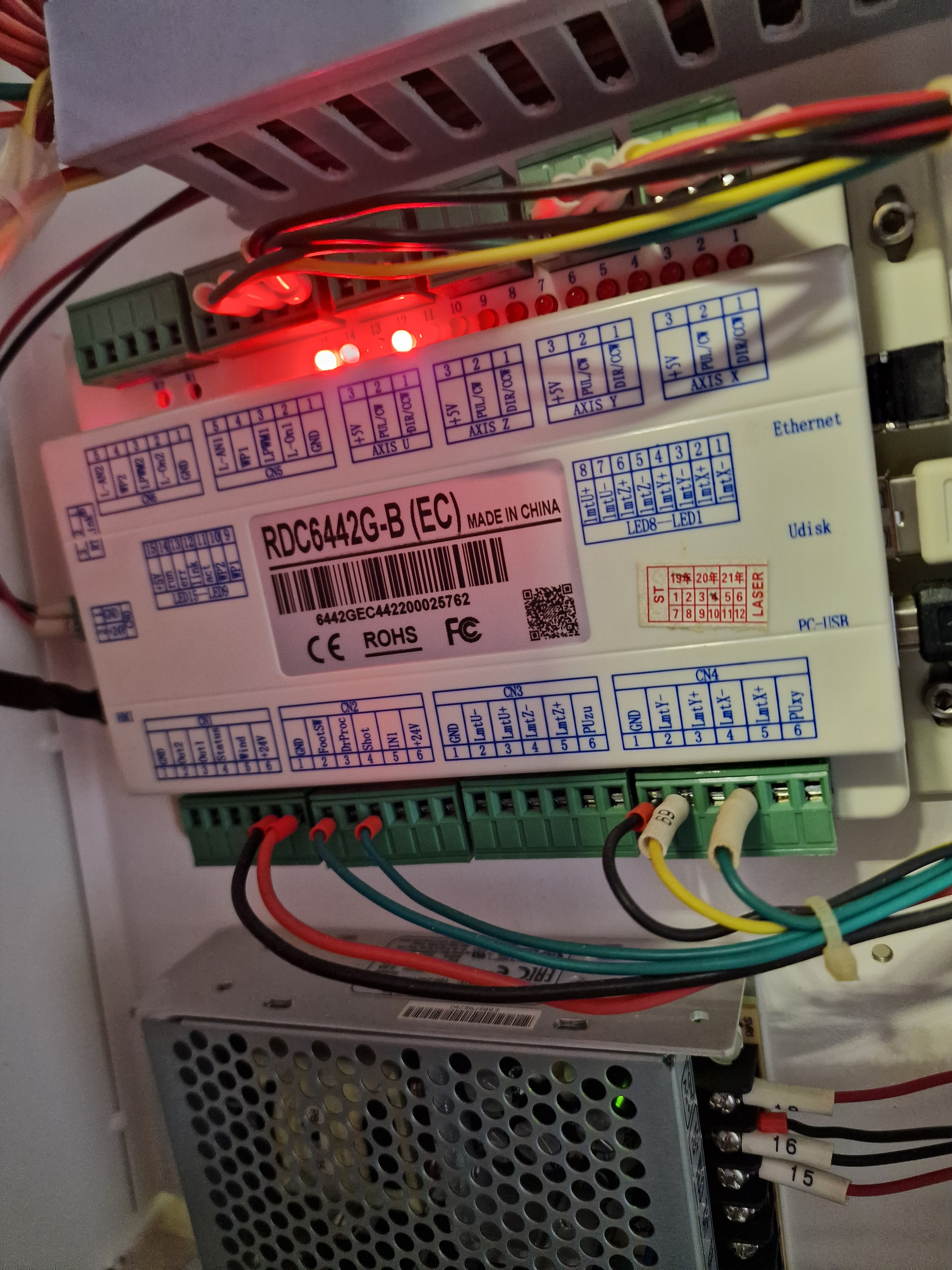
I do not see any wires to the Ruida controller from what might be the 24 V terminals of the perforated silver supply. This could mean:
They’re hidden behind other things in the pictures
The controller is powered from the 36 V supply
Something else is going on
Can you get good pictures of the 5/12/24 V supply terminals and the power terminal block on the left side of the controller? Maybe trace the power wires from the controller while you have your head in there.
Wow you have been through a lot. I had a similar issue a while back. It turned out to be as simple as the lens had become loose in the holder. You’ve probably checked that already though.
I read something somewhere that these are 36v and a failing one would have symptoms like lost steps and a red led flash as you stated. Could be a quick fix if its the issue. I’m going to try looking at it tomorrow whilst cutting and see if the red led illuminates.
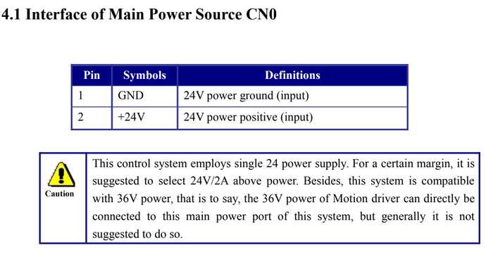
So nothing connected to what the diagram shows as 24 V for the controller. That means the controller is (almost certainly) connected to the 36 V supply, contrary to the doc, unless something truly undocumented is going on.
Try to follow the controller power input wires to wherever they originate …
After a few days of tedious follow-the-evidence problem solving, that would be great.
I think there’s more wobbulation than a loose lens could account for, but it’s certainly worth (re)verifying the mirrors / laser head / lens all sit snug in their sockets. If anything moves when you (try to) wiggle / push it, that could be the problem.
My plan is cut the cat whilst monitoring the leds. Hopefully we will see something which indicates a power supply problem. I’ll remove it to see the label and go from there. Thanks again for your contributions they’re invaluable.
I’ll give anything a go right now. It’s been a painful week of testing and frustration. Something has changed in my machine but I’m sure it will show itself soon. I’ll try this test soon.
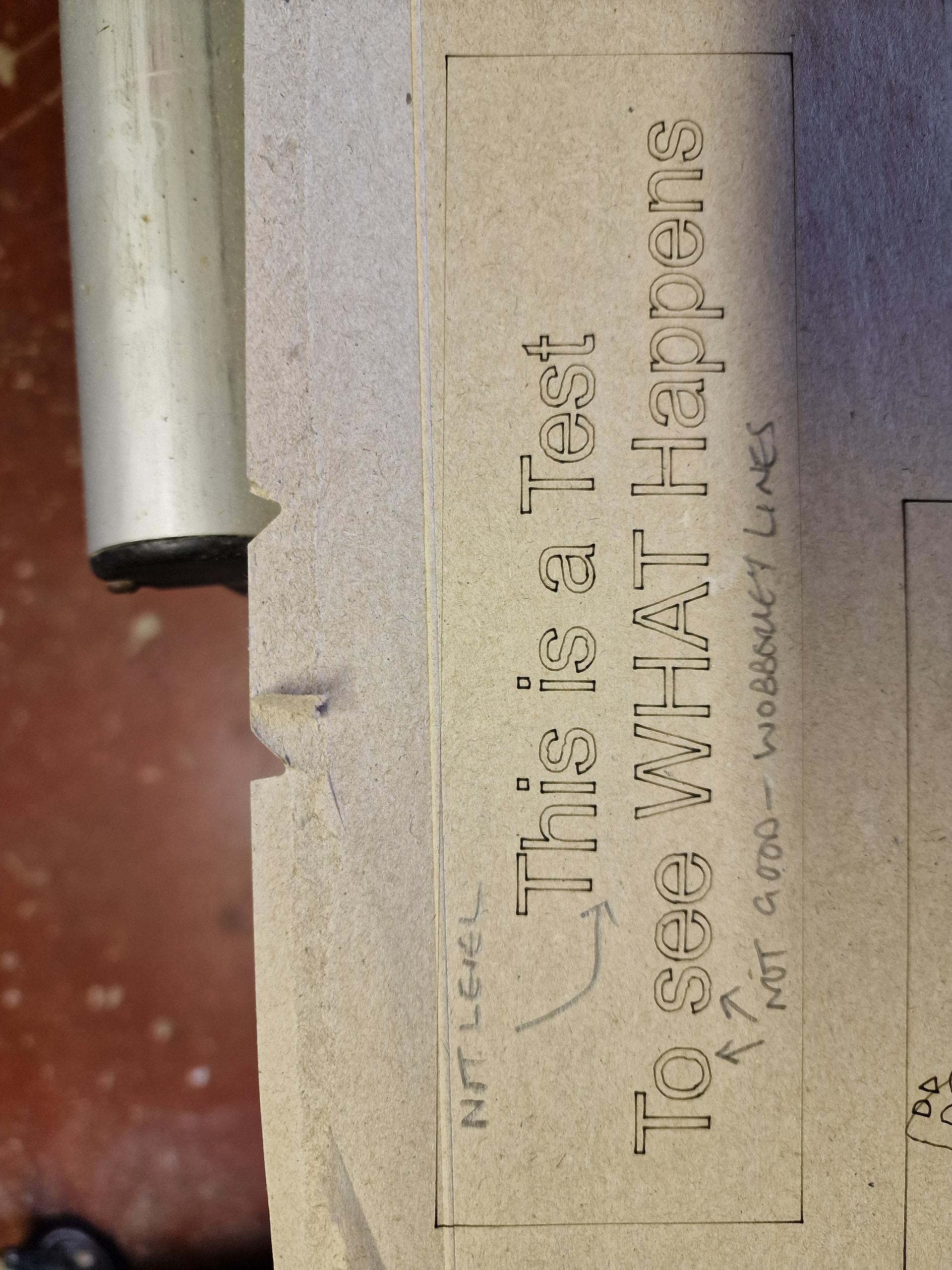
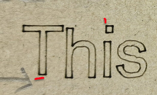
The small wobbles in the letters come free with a large CO₂ laser: you’re watching the laser head mount & gantry flex as the direction changes. Basically, you gotta get used to it, because there’s no real fix.
Small circles look badly (and consistently!) distorted, even though the wobbles are a fraction of a millimeter:
The big circle is 5 mm for an alignment post. The smaller ones are 2 mm and 1 mm, encoding the layer number in a layered paper design.
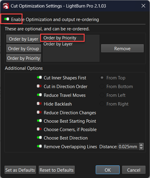
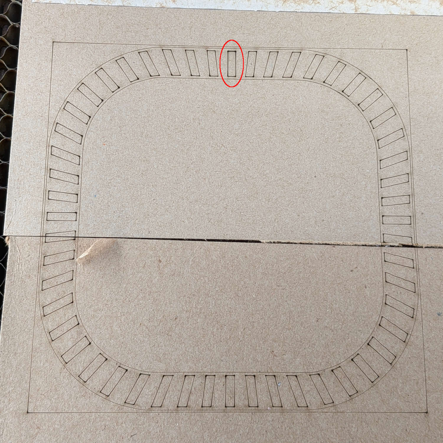
I selected and re-burned the first rectangle to verify it overlaid the initial burn. You could duplicate that rectangle in the design and set the duplicate priority to burn it last in the same job.
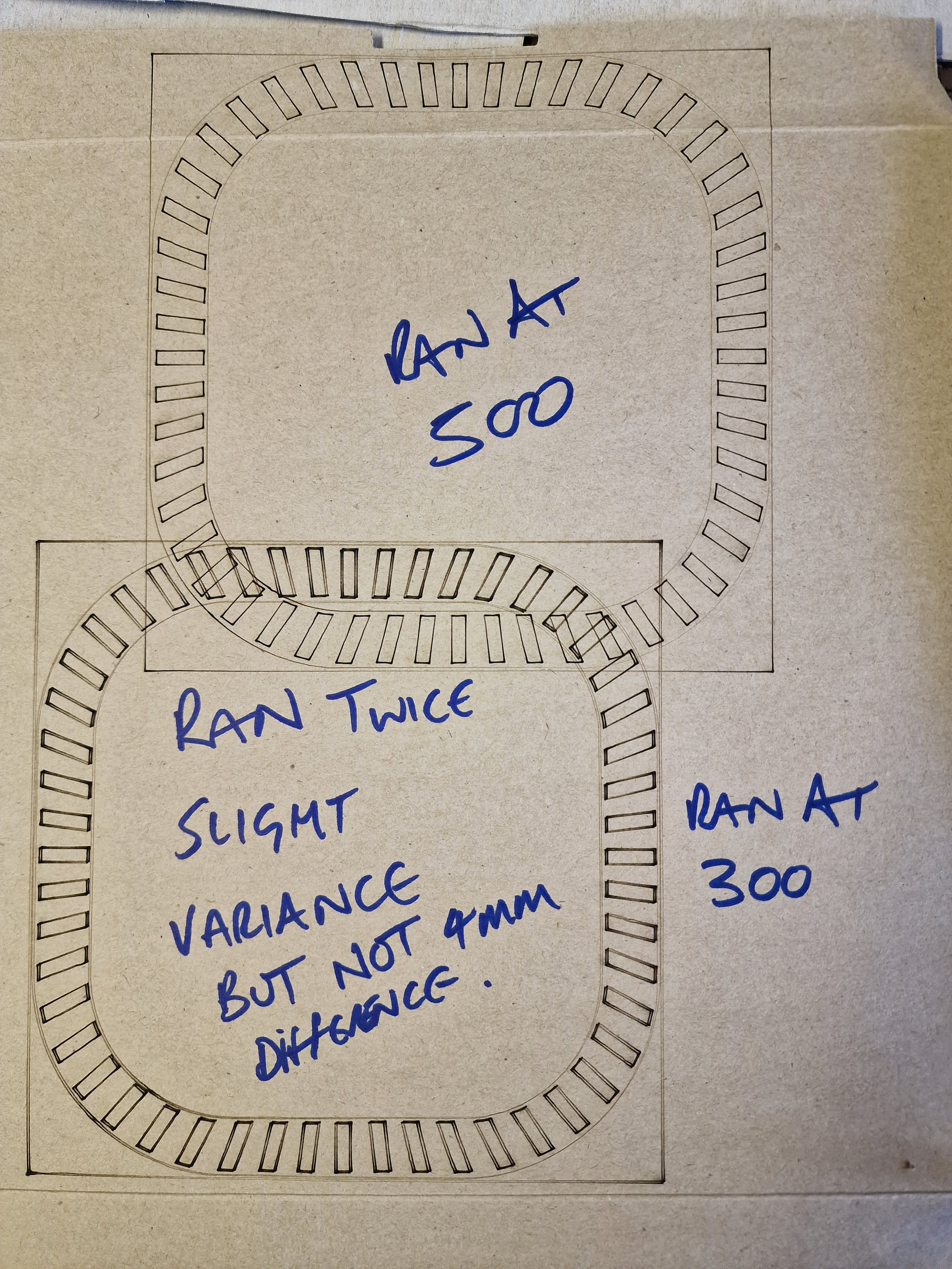
Not as I see it, because the two runs are mis-registered by a millimeter or two, which means Something Is Not Right.
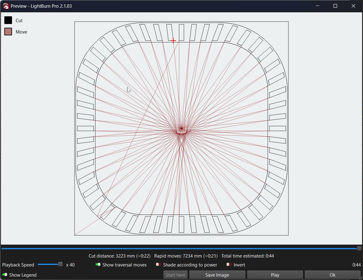
Because the rectangles are engraved clockwise, alternating between 12 and 6 o’clock, I expected a single error would make the last few rectangles in the first pass (those left of 12) match up with the same ones in the second pass.
That is not the case: all of them appear equally offset.
If the cardboard shifted between the first and second passes, however, all the patterns would be offset as shown.
Run two passes again with fresh cardboard taped to the platform and see what happens.