Hello.
I am new to laser and I have a isue.
My laser is turning of slowly and doesnt regulate power.
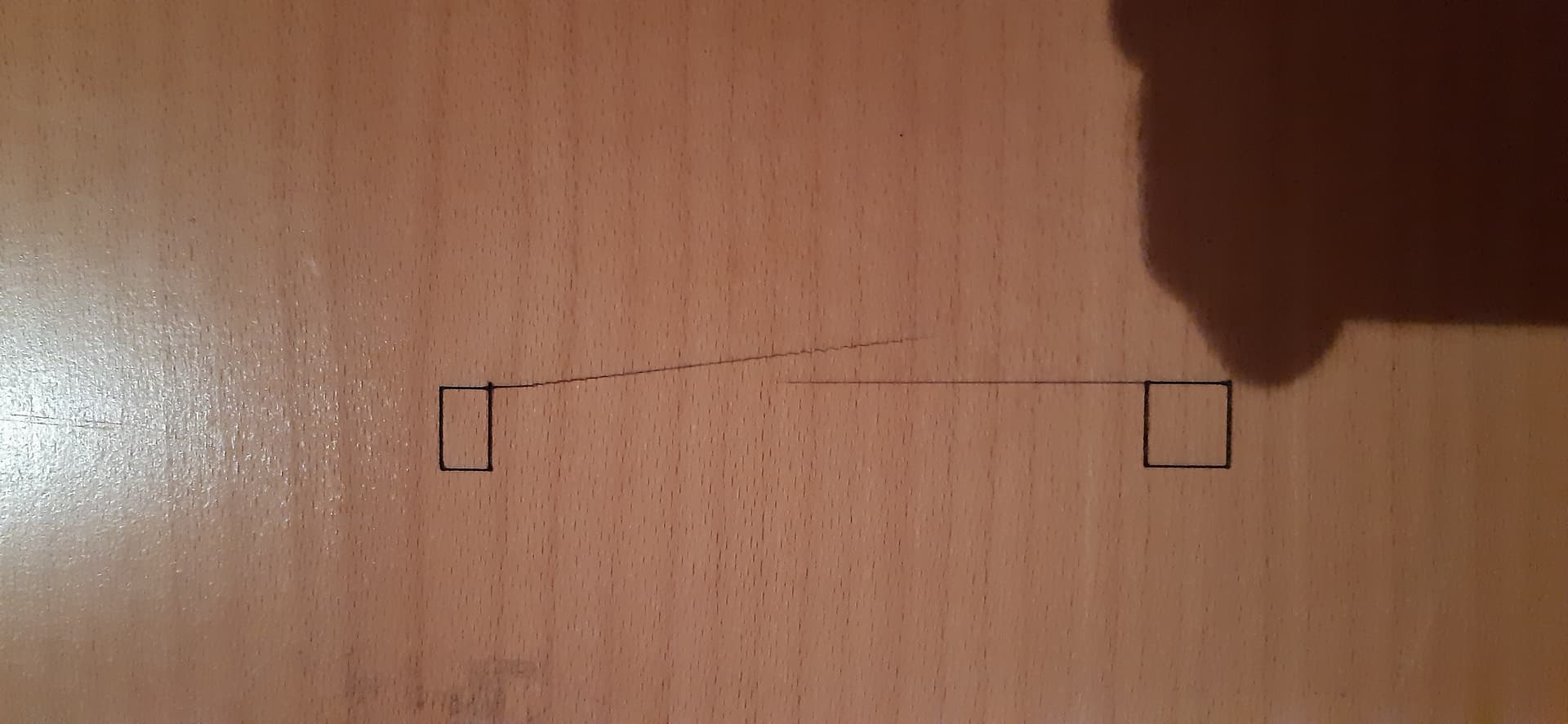
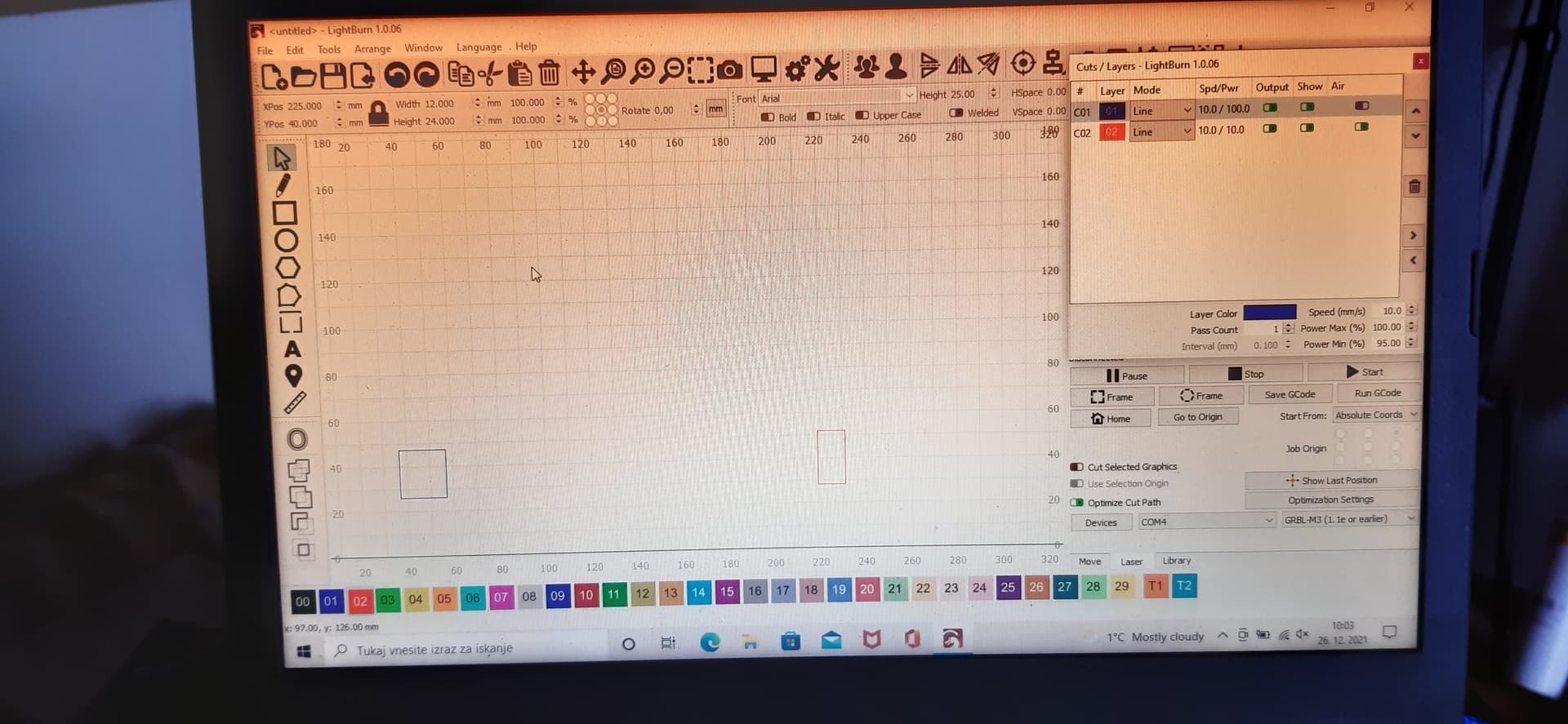
1 square was suposed to be engraved with 100% of power and the other with 10% of power but are the same.
and there were not suposed to be any line between squares but laser was turning off slowly and left a mark.
Is it posible that i have to weak control board. I have Neje 50W A40630 laser from aliexpress.
What device type did you set for this laser? Have you made any changes to settings in LightBurn or your laser after installation? If so, which ones?
Can you run these commands in the console and report back the output?
- $I
- $$
Also, please share the .lbrn file that you used for the test. There may be something going on there.
1 Like
Is there a push button behind the cable in the 2nd picture?
You should not have to ‘tweak’ any hardware the control from the laser is generated by the Nano and has the ability to drive the laser without external hardware.
Double check the configuration of both hardware (laser) and software (lightburn).
Good luck

1 Like
Thank you for replies
The button is for laser test. If Ipush the button the laser starts.
Hope changed the settings $30 to 255 but nothing was different so I changed it back to 1000.
10mm/s is really slow for a diode and for that type of laser is better use mm/min.
@jkwilborn this is how is made the laser interface by neje
You did not include the output of $I in your screenshot. Instead of a photo can you copy the text from the output screen?
I want to confirm GRBL version level.
I suspect at least one of the problems is that you’re on a newer version of GRBL but you have chosen GRBL-M3 as your device type. This would cause your laser not to shutoff between shapes.
If your GRBL version is higher or equal than 1.1f , reconfigure the laser as device type of GRBL and try again.
1 Like
hello
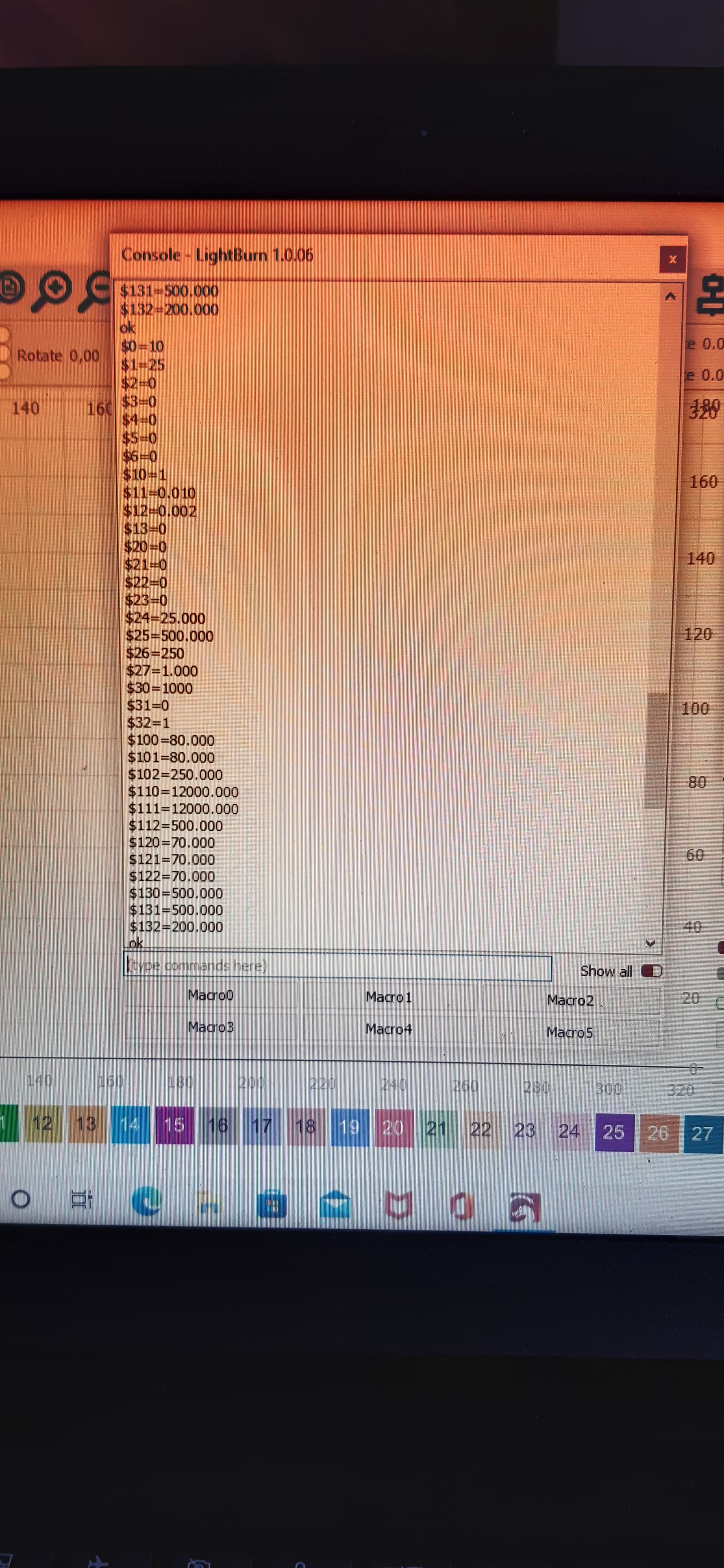
here are my $ setings
$0=10
$1=25
$2=0
$3=0
$4=0
$5=0
$6=0
$10=1
$11=0.010
$12=0.002
$13=0
$20=0
$21=0
$22=0
$23=0
$24=25.000
$25=500.000
$26=250
$27=1.000
$30=1000
$31=0
$32=1
$100=80.000
$101=80.000
$102=250.000
$110=12000.000
$111=12000.000
$112=500.000
$120=70.000
$121=70.000
$122=70.000
$130=500.000
$131=500.000
$132=200.000
Sorry but I didnt find any $I settings (tried in console windov but nothing showes up)
I tried all grbl contolers but same thing hapens (grbl, grbl m3,grbl ltc.)
Can it be that controler is to weak?
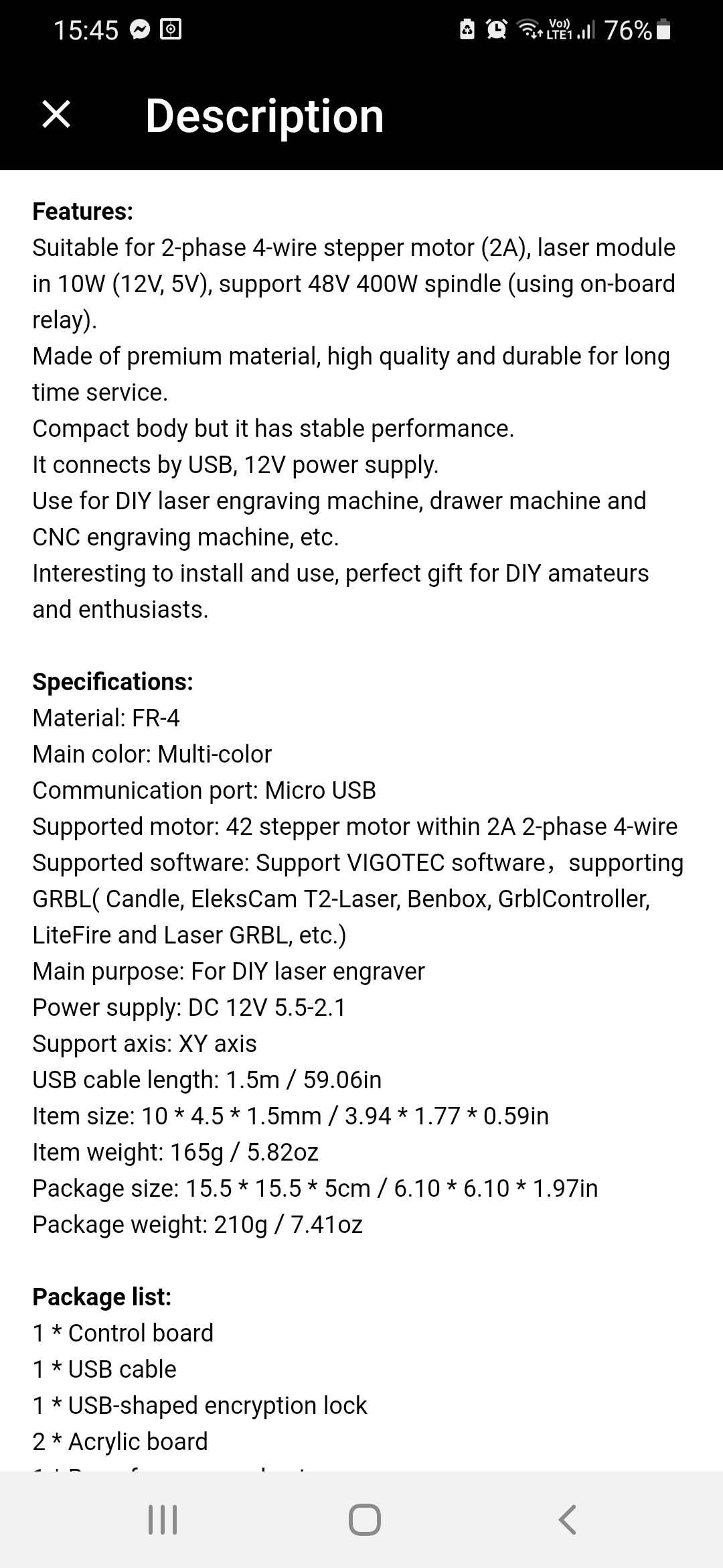
It says here that is sutable for laser module in 10W.
If it is, what other controler would you recomend, for 50W laser, 2xY axis and 1xX axis motor nema 17?
Thanks
Is similar to Mana se by eleksmaker, so i don’t think that the MB is not capable to manage this laser module, Btw if you wanna try, i suggest an MKS DLC32
Can you send the .lbrn file that you used to create the sample. Or a different sample and file.
Did the controller come with GRBL installed or did you install it yourself? If so, where specifically did you get the software? Please link.
Can you turn on “Show all” in console, then power cycle laser, and copy output here?
I don’t think this has anything to do with the controller not being powerful enough. The symptoms you are describing are not power related. But you need to have adequate current from your power adapter.
I’m looking at the photos, do you have 2 separate power supplies one for the controller and one for the laser module adapter? What are the current ratings for those?
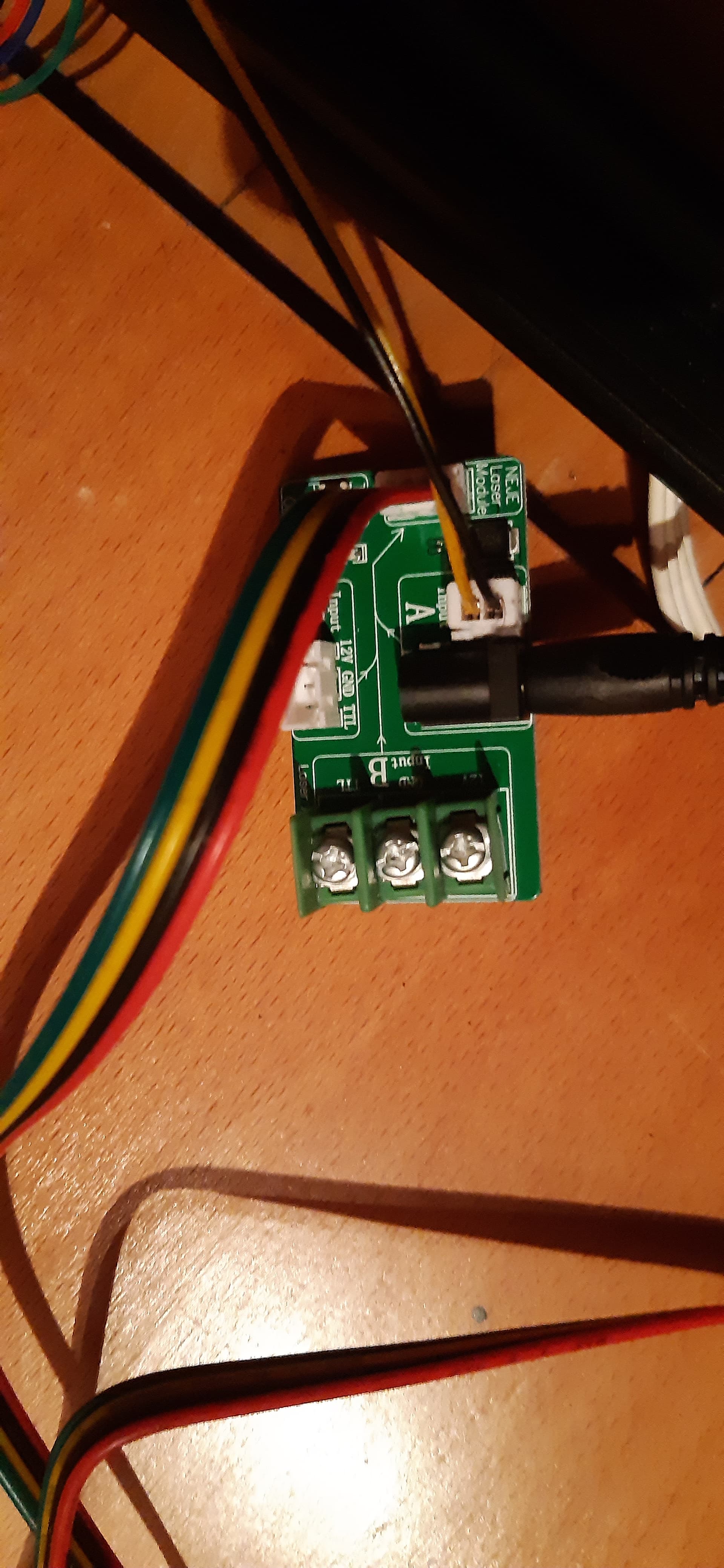
I’m trying to look more carefully at your wiring. It looks like you have a 2-pin input into the laser module adapter plus DC power. And looking at your controller the 2-pin output looks like it’s only giving you +/-. That means you’re not going to get PWM control which means there will be no power modulation.
I think you need to be coming out from the 3-pin +/-/PWM connector and that should go to 3-pin connector on the laser module adapter. No external DC necessary for the laser module.
Setup your device as “GRBL”. Do not mess around with the other ones as that will only confuse things.
Report out your findings.
hello
thanks for replying
this is from console:
Starting stream
G00 G17 G40 G21 G54
G90
M4
M9
G0X37Y26
Layer C01
G1Y47S1000F600
G1X57
G1Y26
G1X37
M8
G0X219Y28
Layer C02
G1Y52S100
G1X231
G1Y28
G1X219
M9
G1S0
M5
G90
G0 X0 Y0
M2
[MSG:Pgm End]
Stream completed in 0:24
I have 2 power suply 1 come with laser and output is 12V, 4A, 48W and for controler I use 12V, 1A.
I didnt instal any grbl so it must have come already instaled.
if I conect it with 3 pin cable laser starts and runs the whole time even when program is off.
try1.lbrn2 (6.8 KB)
Does the laser fire at full power with the button? This overrides the controller and should fire at full power.
If so, you probably have sufficient power supply.
The control board usually doesn’t control the ‘power’ to the laser, just controls the duty cycle of the laser, which requires only a TTL signal, low power and easily supplied by the controller.
Have you enabled the laser in the Machine settings?
At least you should be able to tell if the laser is capable of firing at full power and eliminate the question about it’s power supply.
I was looking for any greeting message when you first power cycle the laser. Is there anything that shows? Make sure that “Show all” is configured in console.
I don’t see anything obviously incorrect in the .lbrn file.
Did this controller come with any instructions? If so, please link or attach here.
This is the part that needs to get sorted out. You will never get power modulation from a 2 wire signal. Can you follow the wires on the 3-wire and make sure the +/-/PWM are connected to the right pins on both sides? Is there a jumper or switch that configures the use of the 3-wire vs 2-wire connector?
Yes the test button run laser at full power
with this module and his interface card works like this, i’ve the same module and the same interface card connected in the same way, the only difference from him is that my MB is an MKS DLC32.
Ok i think i got it.
@Habjan the two pins cable, the black/yellow where is connected on the MB? Is not focused in you pict but i see a “+” and “-”, the connector on the left has a “+” a “-” in the middle and a “PWM/TTL” on the right. I’m quite sure you have connected the black/yellow cable (that has to be only for PWM/TTL) on the 12V output on the controller that is for a fan.
1 Like
I found what looks like the same device on aliexpress.
12V DIY Woodworking Laser Engraver Control Board Driver Controller Board for CNC Engraving Machine| | - AliExpress
Here’s a picture of the underside where it shows you the pins labels.
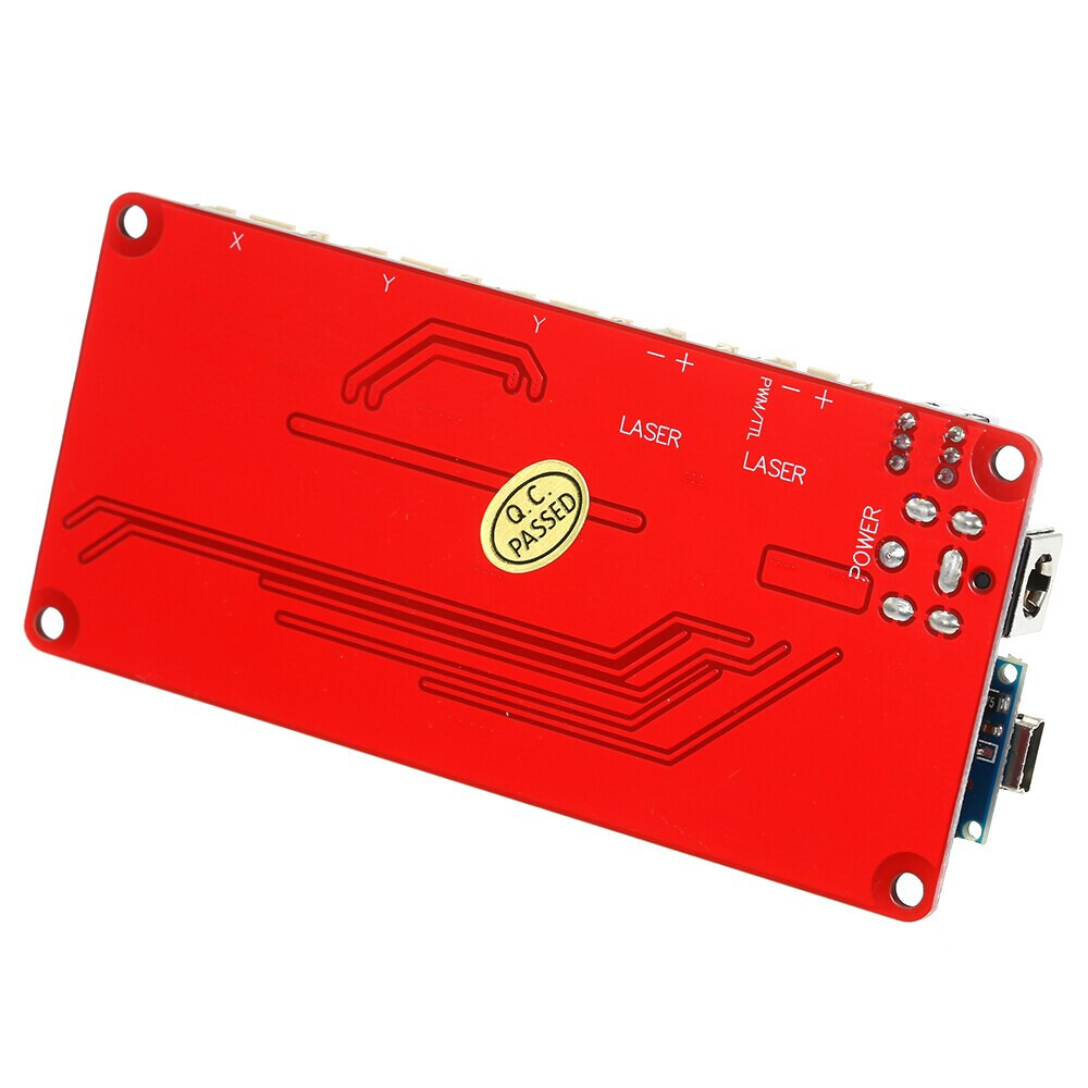
Based on @Habjan’s current wiring he’s going into the 2-pin -/+ connected marked Laser. Is this a dedicated PWM signal or just 12V? I had assumed the latter based on what he’s getting but maybe not based on @killrob’s comment.
I don’t see why this shouldn’t be connected to the 3-pin PWM/-/+ Laser connector but I don’t understand @Habjan’s comment about the laser being always on in that case unless the wires are being crossed somehow.
I think the 2 pins is a 12V, he can leave connection as they are but has only to connect the black wire to the “-” of the 3 pins connector and the yellow wire to the PWM.
and here you are right, the 3 pin cable of the neje module has “+” and signal inverted respect the connector in the controller, the only GND is in the right position.
Seems like a wiring mishap.
Looking at the 1st picture, the bottom connector, above the power is the ‘TTL output’. What do you have plugged into it?
After reading through this I think it should be wired up, very simply…
Power and laser plug into the ‘laser control board’, not the controller. Power from laser comes from this board.
The only other required connections for this to operate are the pwm control.
The ‘TTL output’ of the controller goes to the pwm control of the ‘laser control board’. This can be done with two wires pwm and a common. It must be on the TTL output of the controller.
This should make it functional.
I can’t see what you have plugged into what…really. I can see something plugged into both the TTL and the Laser connectors.
1 Like
I agree with this. But seems he would have to reverse the wires in the connector to line this up. And then only fit on 2 of the 3 pins.
Reading @jkwilborn’s response I think he’s in agreement with this.
Or alternatively I feel like the 3-pin connector would also work if the wiring is correct. Then avoid the power to the laser module adapter. Could use the higher amperage power adapter into the controller assuming they’re both the same polarity plug.
1 Like
He will have to get common (ground) and the pwm (signal or +) correctly oriented.
I suspect it should ‘plug and play’ if it came as a kit.
There is probably no need for 12v to the laser control board, just the signal and ground. I don’t see any active components on that board. The rest of it is self contained, so to speak…
1 Like
I see one IC hiding between the 2-pin input connector and the 4-pin output.
Also, I think he needs to get 12V either from the barrel plug into the laser module adapter or via the 3-pin from the controller otherwise he’ll have no source for 12V to power the laser.