I have also enabled the fire button in the Move window.
Regardless of the setting the intensity of the laser does not change and nothing gets marked.
I have tried 1000 & 2555 settings for $30 and made sure spindle speed had the same value.
I have tried $32 at 0 & 1
The only thing I cannot find confirmation for is the use of the rotary control on top of the laser, it is like on on off switch when on the laser intensity stays the same wherever it is turned
Well silly me. I thought as the frame laser and leads were from the same source they would be wired correctly, wrong.
So I made a text file listing the pin outs for the laser and controller, then the way the lead was wired and found the flaw, Carefully extracted the wires that needed to be swapped and Bob’s your uncle
I cannot accept responsibility if you do this wrong. If you are not sure about the wiring seek professional help.
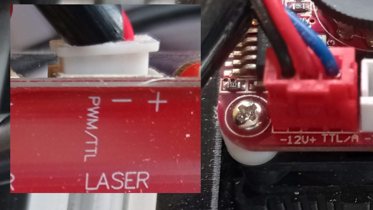
Looking at my laser I saw the socket marked - 12v + TTL. So I thought the left pin 1 - 12v DC the
middle pin was + 12v DC and the right pin was for the TTL signal.
On the back of the control board I saw the same markings.
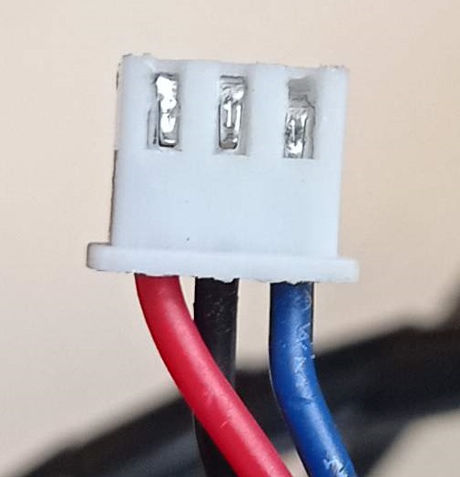
When I looked at the lead I expected the red wire would connect to + 12v DC on the laser & controller, black to both the - 12v DC and blue to the TTL. This was not so. it was a bit fiddly to swap the wires over but when I did the laser worked first time.
The thing to be careful about is the wires connect to the pins after, you may get no power. This may be because if the 3 silver bits in the picture are not fully seated they may not reach the pins on the PCB
I think it is actually the cable. During my time of trying to get this to work I purchased an entirely different model of controller board, same problem, same solution. I told the people who sold me the laser & frame and so hopefully they will do something before shipping new orders.
Next project is to install drag chains to tidy up the cables.