Laser_power_inline

Yes this happens to me to from time to time the solution for me is to stop it from the marlin menu Laser control maybe they will fix it on the next update.
I’m still drying to understand the engraving process for images what i can tell for sure is that it works complete different from fill.
Here’s is some pictures from my tests the picture the preview my settings and the results.

settings

Your settings are fine, you’re probably just missing inline mode. Oz said it should be in the next release. You’ll have to set it up in the firmware too. Does it seem to “studder” a lot? It’s looks like you’re over-burning everything from the stall for intensity change that’s mentioned way up somewhere in this thread. Inline mode with some config settings in Marlin takes that away so it can change intensity without stopping.

But i already have inline mode enabled as i have mentioned before.
Here is a link with my settings
https://github.com/gminadak/Marlin/tree/TopsCNC-bugfix-2.0.x-SKR13-TMC2130
I have almost the same settings as you have the only difference here is that you are using a CO2 laser and i use a 5W laser diode.
So i didn’t change the SPINDLE_LASER_FREQUENCY, SPINDLE_LASER_POWERUP_DELAY (this is ignored anyway) and maybe some other options.
And i use the inline option on my gcode.
Better but not perfect.

Here is another test the only thing i changed is the DPI(lower) and Power

I almost suspect you’re using a pin that’s running on/with another timer. In your image above of the twisted thing you can see that the laser isn’t wanting to turn off when it’s supposed to. Are you using the fan PWM - with the other side hooked to 5V somewhere or what?

I’m using the signal from the servo pin
My laser have 3 wires 12v+ 12v- (S) the Power is directly from the PSU and only the Signal is connected to the board PWM output.
Marked with red circle.

1 Like

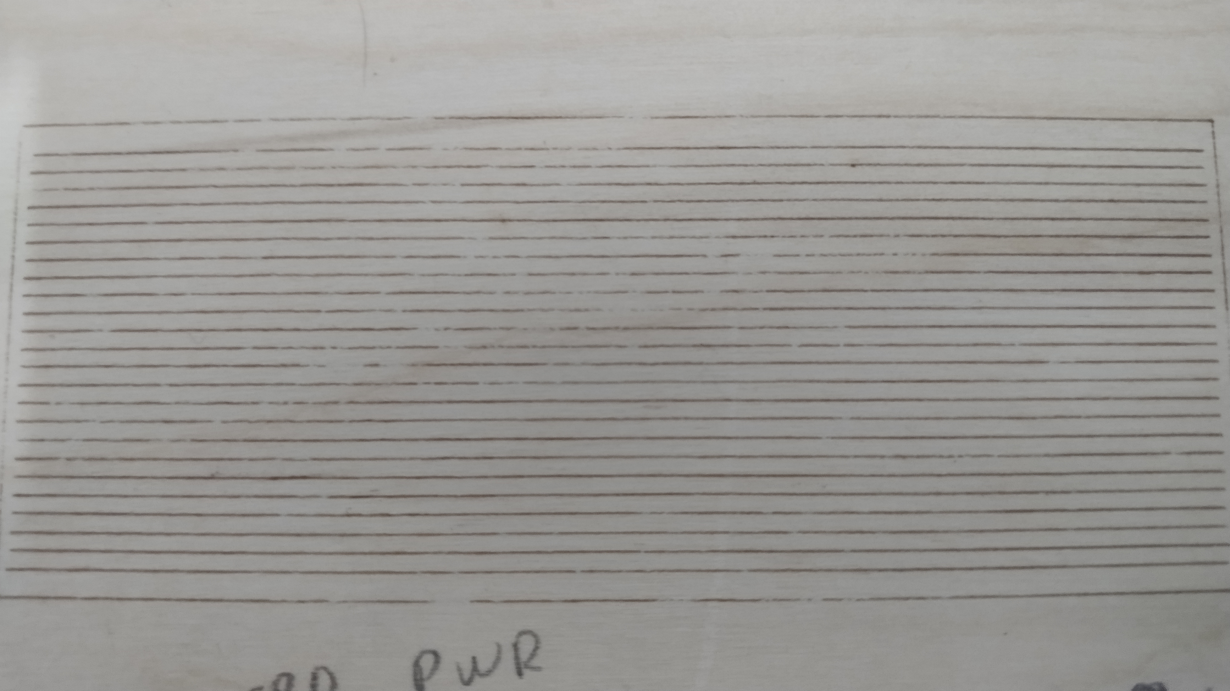
After reading this post link i made a line test.
As you can see the laser starts/stops where is supposed to BUT for some reason the lines isn’t consistent and i can’t understand why…maybe it’s the wood? marlin dont send the correct power? laser is out of focus?, to fast? i don’t have a clue.
the txt file is my gcode

test_LINES.txt (1.7 KB)

Maybe i’m wrong but i just found that the marlin developers don’t have push the changes to bugfix 2.0.X
the file i checked is “spindle_laser.cpp”
Yours on line 85 is “set_ocr(upower_to_ocr(upwr));” as is with the changes from “Luu Lac”
While mine and on marlin bugfix 2.0.X on line 82 is “set_ocr(translate_power(inpow));”
Now i don’t know much about github and marlin code or if this have to do with my problem but i don’t have this changes.

Any desire to pull my latest into yours and start from there again?

The one thing I wonder is what your diode is going to do with only 3.3V if it wants 5V. :frowning: Mine would only go to about 2/3 power PWMing at 3.3V. I’d also up the frequency but don’t feel like doing the math that Oz would to figure out the fastest you can switch without losing an on/off event.

1 Like

I thought that the specific pin is 5v all other pins like fans etc have a resistor and they are 12v i can’t use them(only possible if i solder the signal from the laser TTL/PWM to GATE of the mosfet this is how i did it on the melzi board)…this informations is from what i have read on skr/marlin FB pages i don’t have any way to confirm this. :frowning:
I will get your latest and test it i tried to do that with the version from “Luu Lac” but gives me an error

Marlin\src\gcode\control\M3-M5.cpp: In static member function ‘static void GcodeSuite::M3_M4(bool)’:
Marlin\src\gcode\control\M3-M5.cpp:84:31: error: ‘dpower_to_upower’ was not declared in this scope
84 | cutter.inline_power(dpower_to_upower(get_s_power()));
| ^~~~~~~~~~~~~~~~
Compiling .pio\build\LPC1768\src\src\gcode\control\M999.cpp.o
*** [.pio\build\LPC1768\src\src\gcode\control\M3-M5.cpp.o] Error 1

Yeah, the error I know about. He forgot to suffix one of his changes with “planner.” and it broke the build. That should be fixed in mine right now and I’ve been running the laser more or less non-stop without issue except for the one that I mentioned here when I hit stop.

The 5V output on pin 2.0 has some funky stuff going on somewhere inside. There’s some register calls that set the chip to actually output 5V but that appeared to only be run in the Servo code. You can test if you want, just measure voltage from pin 2.0 to GND and see if you’re getting 3.3V or 5.0V at 100% laser power. Disconnect laser power if you want to ensure it doesn’t turn on.

1 Like

Yeah it’s 3.35
i just measure it…

Not that big of a problem, you’re just maxxed at 3.3/5 percent right now. That said, if your controller isn’t happy seeing 3.3V, or is using actual 5V logic, then you’re in undefined behavior territory. You can get a fast switching transistor and plug 5V into it via a PNP transistor to boost it but I’m not sure about protection on the pin and all that stuff, so you’d have to google. Or get me interested in solving it for you. :stuck_out_tongue:

Look up a “Logic Level Converter”, they’re cheap. This is actually the one I’m using, though you only need it for a single pin:

pin 2.0 goes to the IN side where 3.3V and GND are and then 5V and GND are on the other side and OUT goes to the laser PSU.

I would suggest focusing on that swirl filled thing on the left of one of the pics before going for images. If you look at the dragon in that same pic you see the right line doesn’t close, and if you look at the edges of the image ones you’ll see that they’re not crisp. A single “pixel” shift will have a pretty big impact. When you see a few in a row there and then they shift a few tenths of a mm, it will be visible.

All that said, set your min power way higher than you normally would, knowing that “min” is going to be relative to 3.3V for now. Your image is missing low-level details because 10% right now isn’t 10%. It’s .33 instead of .5. Also note that if you’re using inline to do the image your power is directly related to your speed. Slower speed less power, faster speed more power, for the same effect. Toward the end of making that image above I was tuning speed instead of intensity to get the balance between dark and light right. Not claiming it’s perfect, just something you’ll have to do as well.

The exact same gcode from your fork
I must confirm that first but it seems the best solution will be to just solder the signal to the GATE from the fan mosfet.

That looks pretty good to me! I’d do another of those filled spirals and make sure you don’t have any issues with the PWM frequency or missing steps and then go for some images! :slight_smile:

As for how to hook it up I’m not sure. The FAN with be powered at VIN so you may fry the diode that way.

1 Like

My understand is the fan pin - is used for 2 wire diodes to do the PWM because it has a MOSFET before it and can handle the current of switching it directly. You have an external box to do that.

If it’s putting out 5V at the gate though, I’d also jumper that. Just make sure it’s not on a conflicting PWM timer before you decide that.

1 Like

Looks better

1 Like

Also i can confirm that the voltage on the GATE from FAN mosfet is 4.89v but i thing the best solution is the one with the Logic converter as you mention above.

1 Like

Awesome and congrats!! :slight_smile:

I’m just getting the new panel on my K40 cut and installed. Cut wrong 3 times. Glad I bought 10 of the black sheets lol

1 Like

Very good work
Even better from the original