I need to cut some stencils for a solder paste pcb application. I tried the lead in / out option, but no matter what I do is show an outside cut (on a rectangle).
Change the angle to negative same behavior (outside cut).
Change length to lead in / out same behavior.
Change the lead in to lead out (not what I want) same behaviour.
Change direction same behavior.
Power is set to min 25 max 35 with a 150mm speed.
Machine is a a Shenhui (500x700) with Ruida RDLC 320 80 Watt RECI tube.
LB 0.9.07 full licence (just extended).
Any advice?
P.S.
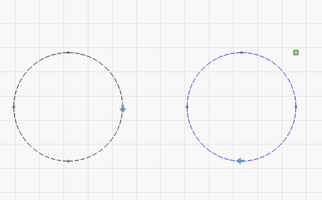
Just tried on a circle and is working properly. On a rectangle is not.
Gabi
For what it’s worth, I can’t seem to get it to behave properly either. Even on circles, it appears to work properly on the first object, but not on the second.
Didn’t try two or more, but since you try it and is behaving badly I think OZ need to have a look and test the feature more. I know is Sunday, but is my day off from work and day in on my projects. Till this will be fixed I will try to use raster to have that stencil usable. I don’t have many hopes on raster. It will make a mess, but since I don’t have any alternative …
I found it best to ablate the mylar with raster engraving instead of cutting it. Cutting leaves ridges that cause problems when spreading the paste. Ablating vaporizes the mylar leaving the edges smooth. You can also use even lower power and etch notes onto the surface too.
May I ask about your settings? I know every machine is different, but it will very helpful to have a start point. If you can’t give that I’ll understand. I don’t mind experimenting.
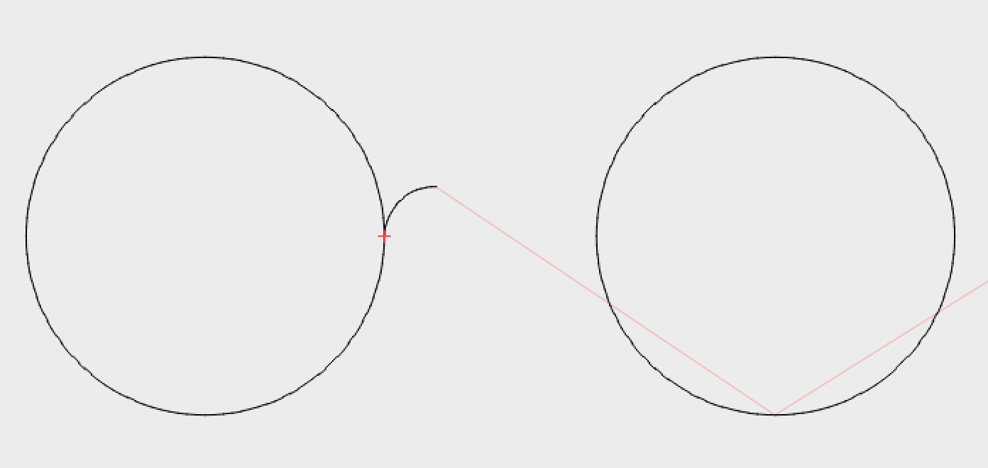
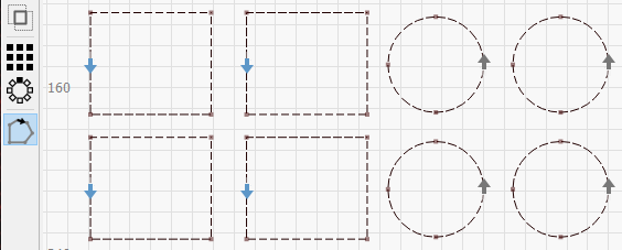
If you want to use lead-in on a rectangle, you’d need to insert a new point on the side, and set the start point there, to give the lead-in somewhere to go. I’ve just tried it with multiple shapes, and it 's working as expected for me. Chris - which version are you running? Your second circle is blue, which implies a different layer. Did you set the lead-in option on that layer too?
Converted rectangles to paths, used node edit to add a single new node in the middle of the left side, then used ‘Set start point’ to mark that point as the cut start:
Doesn’t seem to be working right for me. No matter what I do the lead-in is always on the outside of the shape. What’s the trick to making it on the inside? I thought that reversing direction (blue arrow) would do it, but nope.
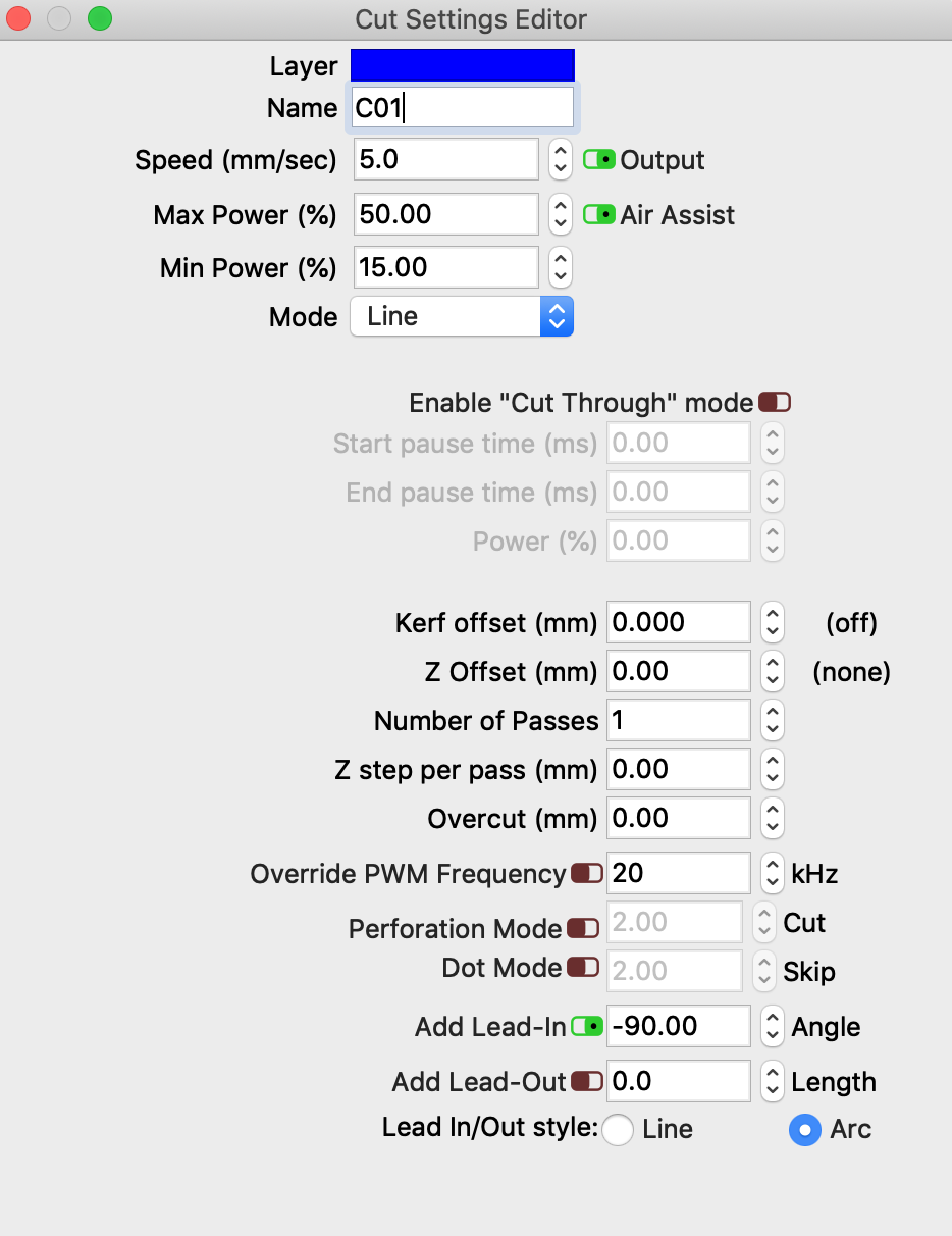
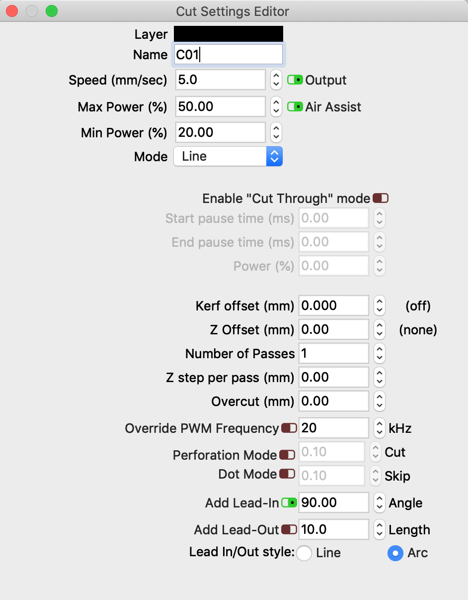
Sorry - I missed that you had the second layer settings posted. Your second layer (blue) has a zero-length for the lead in, which explains why that didn’t work.
Ah! I have to tell you that I didn’t pick up on the fact that the length field was actually for the lead-in. Seems obvious now, but perhaps the lead-in/lead-out fields could be separated from the buttons to enable the function(s)? Just a suggestion. I remember looking at it and thinking why is there only a length value for the lead-out function. Clearly -
Hey thx — I’m just getting started with cutting paste stencils in mylar using a RUIDA-based machine. For years previously I used an Epilog laser with a simple printer-like driver, so I could cut directly from Pentalogix Viewmate. Without a direct driver, I don’t have a good path from Gerber to cutter.
Could you offer some quick suggestions on that? I would be happy to pay for consulting time, by the way — this is a commercial thing.
I use Eagle, and a ULP called “cream-dxf”. All it does is export the “cream” layer (which is the location of where the solder paste needs to go) as a DXF file. You can also do this in the CAM processor without the ULP script. Viewmate should be able to export a layer as DXF.
Then import the DXF into LightBurn and add other stuff like a cutout border so it fits in whatever solder paste machine you’re using. Set the imported DXF as “Fill” so it ablates the mylar. You’ll need to do some tests to find the best settings.
The last few times I’ve been using the same process, but with a cheap “scrapbooking” vinyl cutter (a Silhouette Portrait) instead of the laser because it fits on my desk so is more convenient. Both are about the same quality-wise, but the vinyl cutter is a bit more work because you have to clean the weeded bits off the sticky backing.