I’ve been doing some messing about this morning. I know that apparently CO2 lasers are better for this sort of thing and also that wood is not an ideal medium. Just getting that out of the way.
So I took a grayscale PNG that is intended to be used as a depth map for making a 3D illusion engraving and experimented with various settings on my machine engraving on a piece of Baltic birch plywood. Thought some others might find this useful and save them some time.
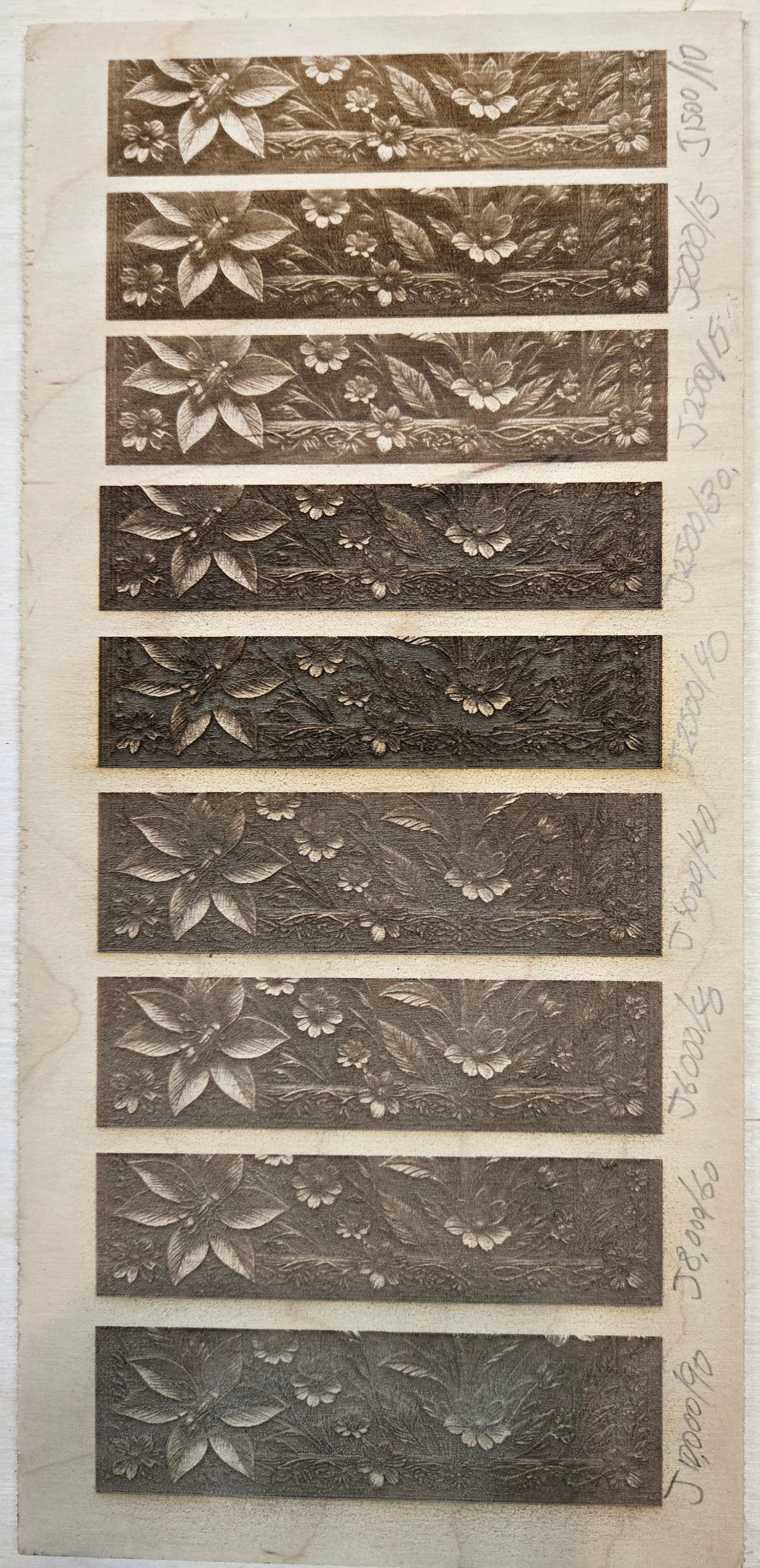
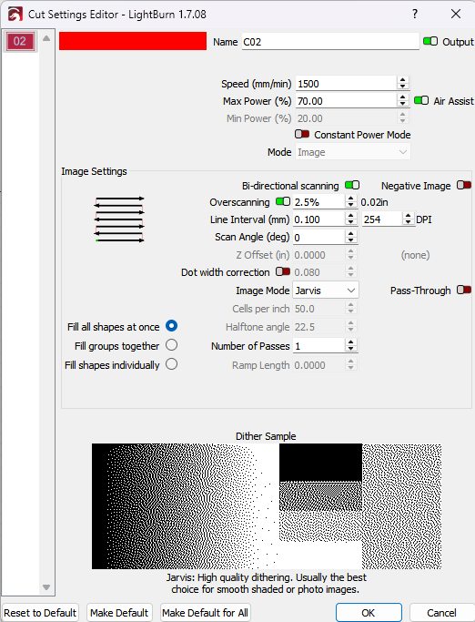
All of these tests were done only by varying the speed and max power on the image cut layer. I used Jarvis mode for all of them. In the pictures I’ve written the speed/power next to each test. Note that having the laser scan with the grain vs. across the grain makes a huge difference in the smoothness of the engraving, which I suppose makes since.
In the cut settings window are you supposed to make the line interval DPI match the DPI of the image? I have no idea why lightburn chose the DPI it did.
I am less than educated on how to find these, or know that is what it is. I am not even sure I understand the concept of “depth” on a greyscale file.
I do understand the concept that shadowing tricks the brain into thinking it has depth.
Do you know of a tutorial link where I can learn more about depth maps relating to images?
Lightburn did not choose, it just remembered the setting from a previous project.
I have no idea either. But I do know burning burning wood tends to reduce the resultant resolution. Most times, I use 254LPI (0.1mm interval) because I see little improvement at 318LPI with my 10w diode.
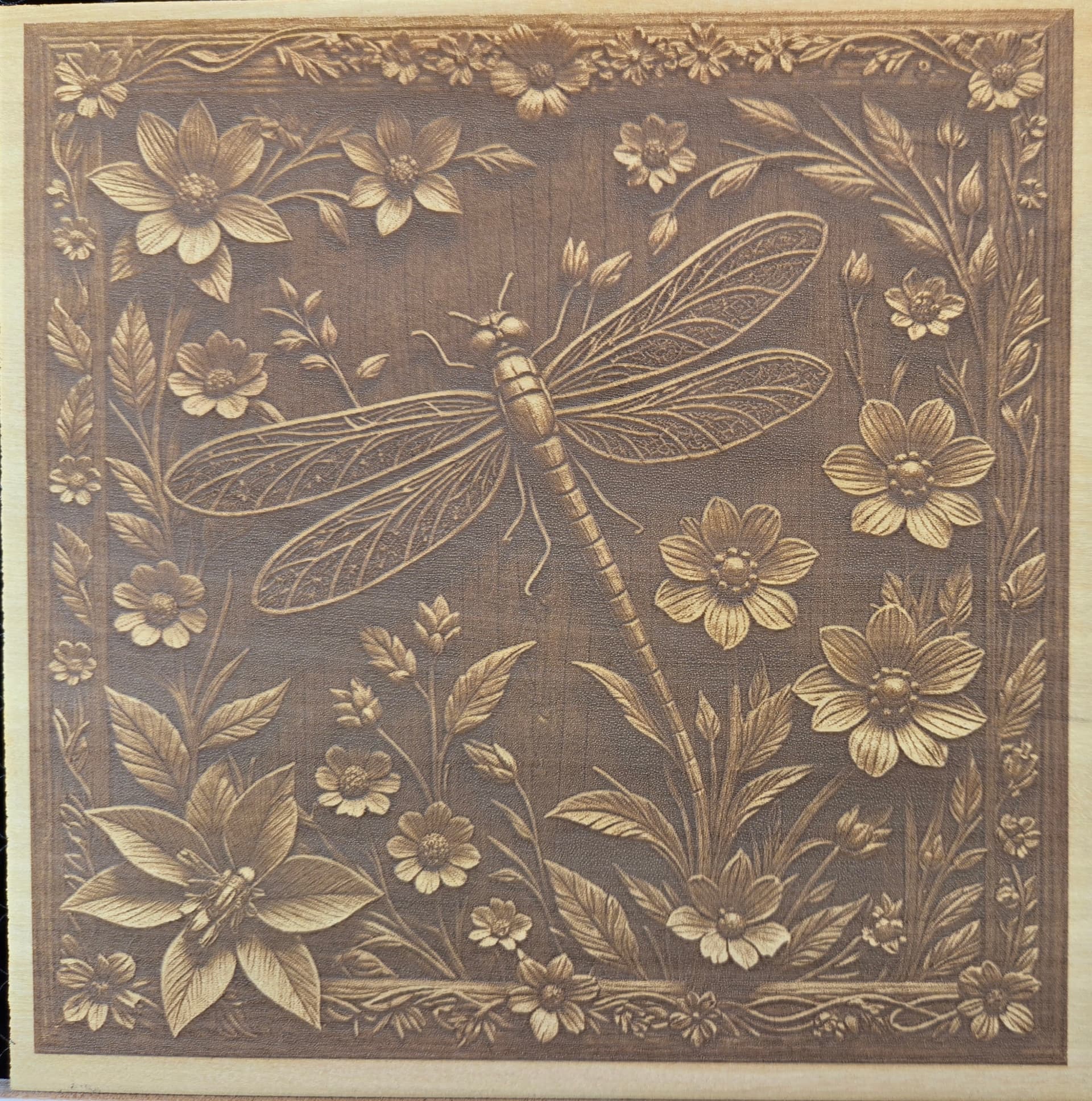
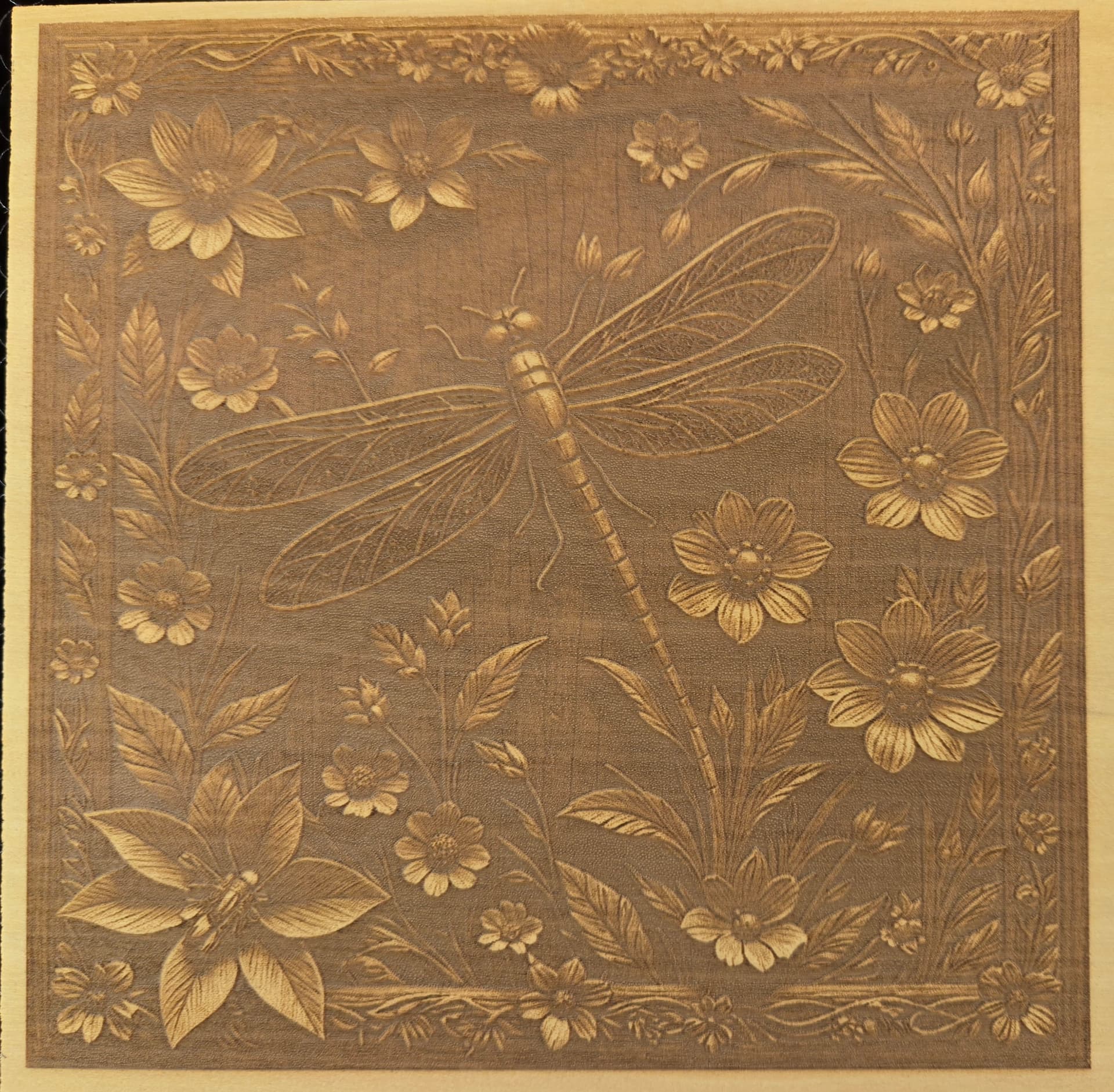
Here is the entire image engraved on a piece of yellowheart wood. Using Jarvis, speed 4000 and max power 15%. The first pic is the first engraving. Second I ran the whole thing again with the same settings. Third I lightly sanded with 220 grit.
If you wish Lightburn to not modify the original artwork, you use the passthrough option in the cut/layer edit window. This is used with output, such as Imag-R or other processed images when you don’t want Lightburn to change the created image.
If passthrough is not enabled, Lightburn will dither or make the dpi as the user has set within the cuts/layer window.
You are not using grayscale anywhere that I can see, so I think you mis-labled the name of this thread. Don’t know if it matters or not.
LED lasers do well with grayscale, fiber lasers don’t do well with a grayscale and co2 use it for depth. If you speak about grayscale and use a dither, it’s not a grayscale, it’s a dithered photo, much like a printing press.
@bulldog has some very good image work with lasers, might want to check some of his work out.
Fiber machines, take out material, this really doesn’t occur with an led, so fiber machines can make use of 3Dslice mode Lightburn created.
Those are two different settings that should not be mixed. The DPI/LPI setting in LB defines the steps it uses to raster your image. If you set it to 1 LPI, it will do one (scan) line per inch and the hop another inch and do the next line. You need to match this with the capabilities of your laser. It’s a physical value. You should set it to the height (size) of your laser spot. When doing so, each line that is lasered is directly following the next line. If you decrease the value, you will get space between the lines, if you increase it, the lines will overlap.
Thats so interesting. I have been thinking along similar lines but haven’t had time to experiment yet.
I had thought it would be hard to control the area’s because of overlap but am sure it would give some interesting results with practice.
Check out my other post using the same image and slate coasters. Once I found the right settings they came out great. I might try redoing the wood tests using grayscale mode instead of jarvis.
I have been watching that other post on slate and its a great bit of work and encouraged me to pursue some ideas I have been forming.
I was finding that images can be difficult as when one area has good definition others dont and wanted to work with layers and power levels to find a sweetspot.
How soft is Yellowheart,
I used some general builders wood called White-deel, its pretty soft timber and it took an image really well at low power apart from the grain. I figured if the power is low enough the second layer could enhance the areas that needed more definition while not overburning the first layer.
I have been thinking of trying layers of trace but not in as advanced a way as yourself and I thought image software would be useful/necessary to adjust specific areas and that Tace might be less controlable.
Your work is very controlled so you obviously have taken your time with it.
This is another technique that I have demonstrated - Which I call painting with the laser. I will be doing a video in a few weeks demonstrating what I stated above. Brian