LightBurn + Atomstack A20 MAX - Engraving Accuracy

Dear experts,
I am new to Laser engraver and just got Atomstack A20 MAX, and making some test engraving with LightBURN software.

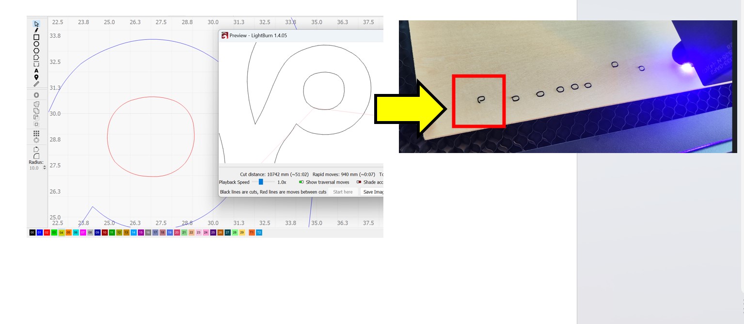
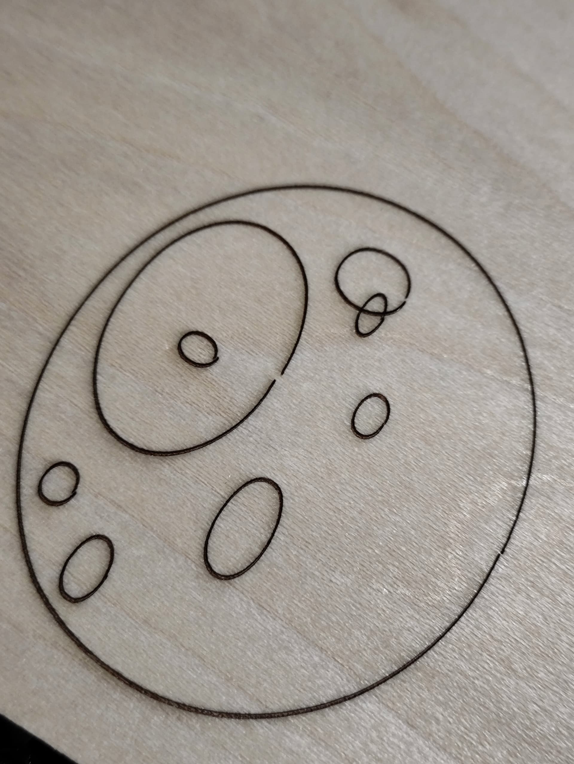
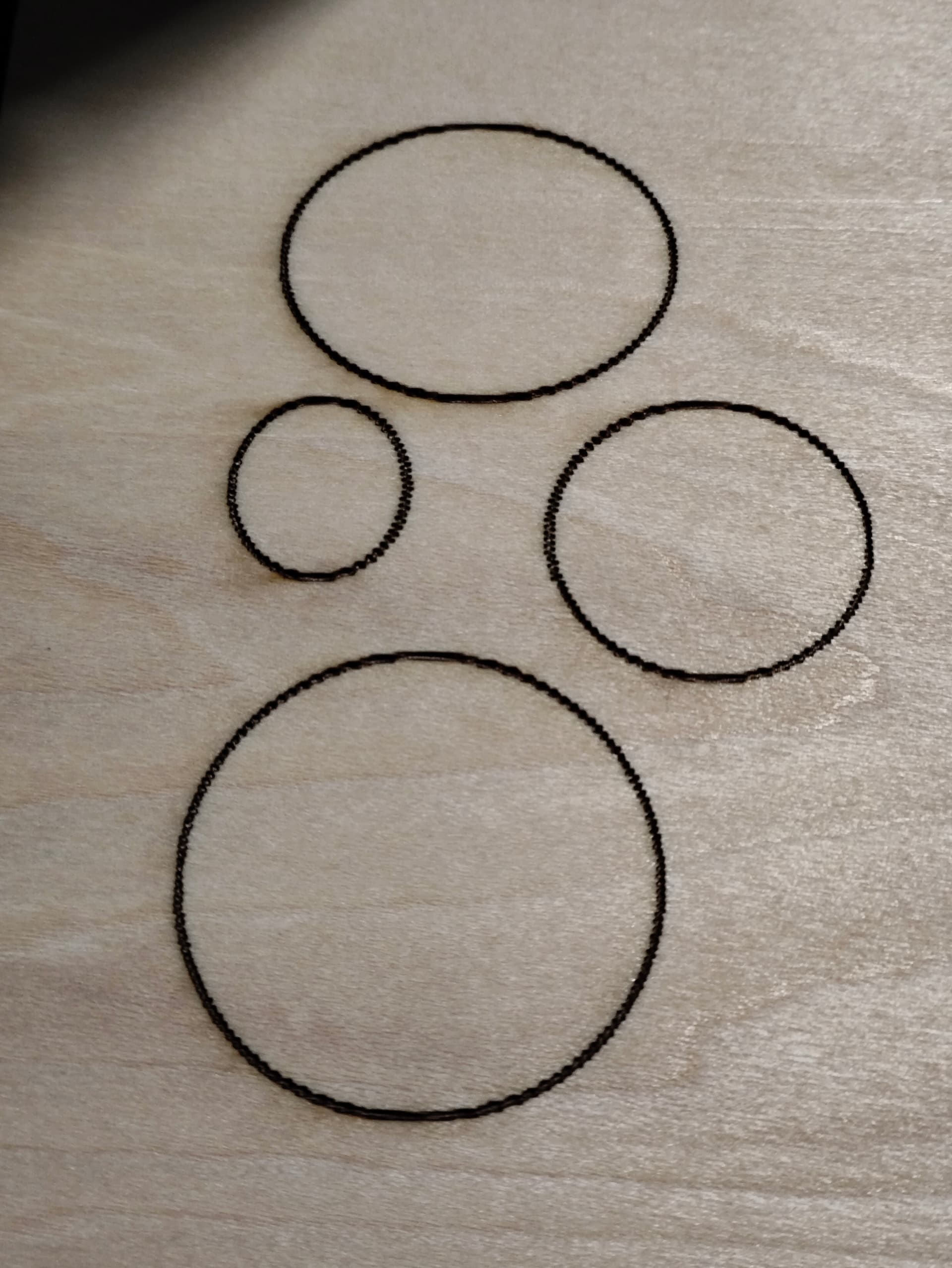
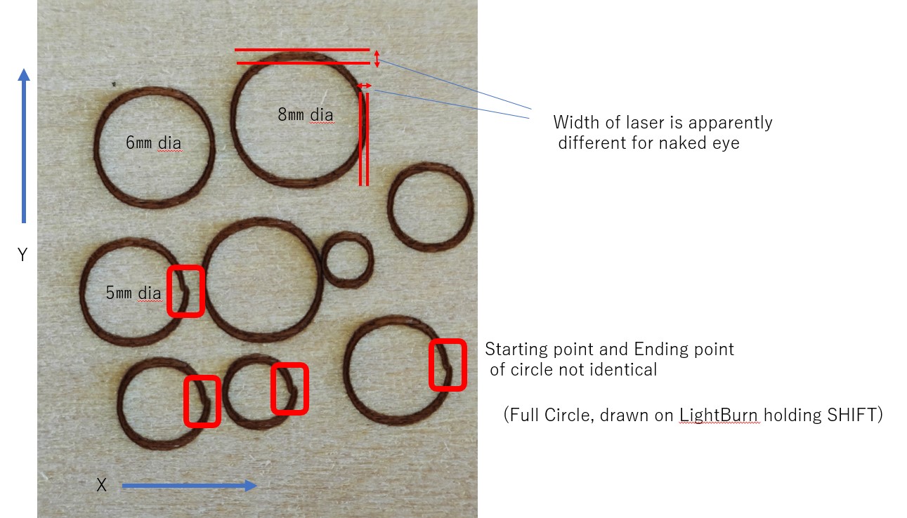
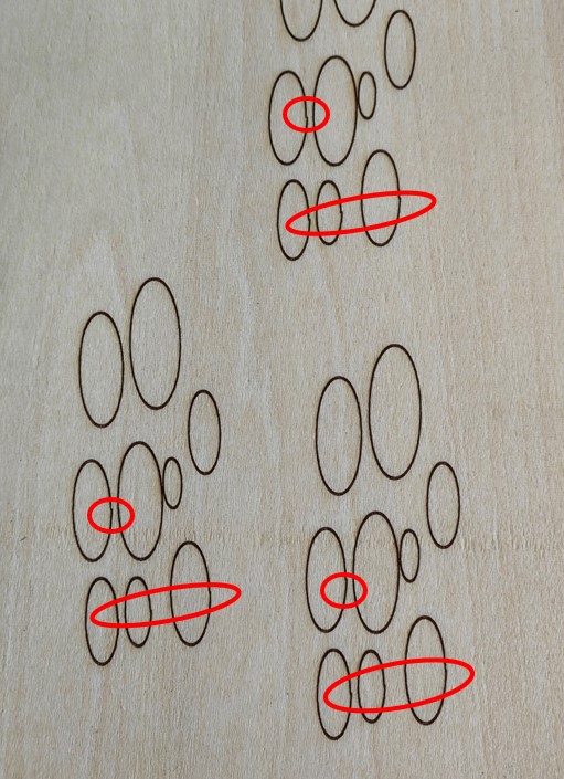
As to the accuracy, I do not get quite satisfying results as shown on the photo,

On LightBurn, the graphic is firmly designed but after laser processing, the lines do not match (circle cannot be completed in a firm way, path does not connect exactly)

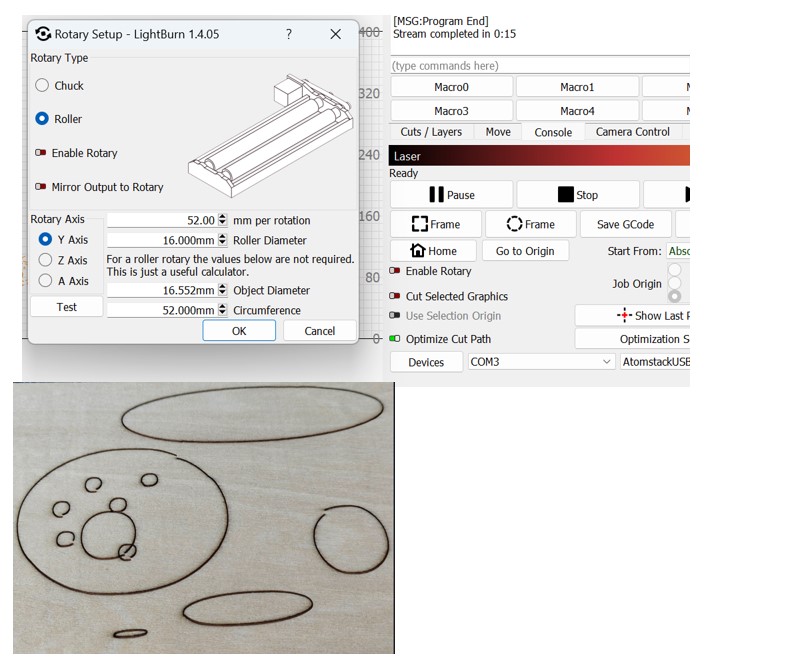
Could this be potentially a setting issue?
Or any potential defect in the hardware?
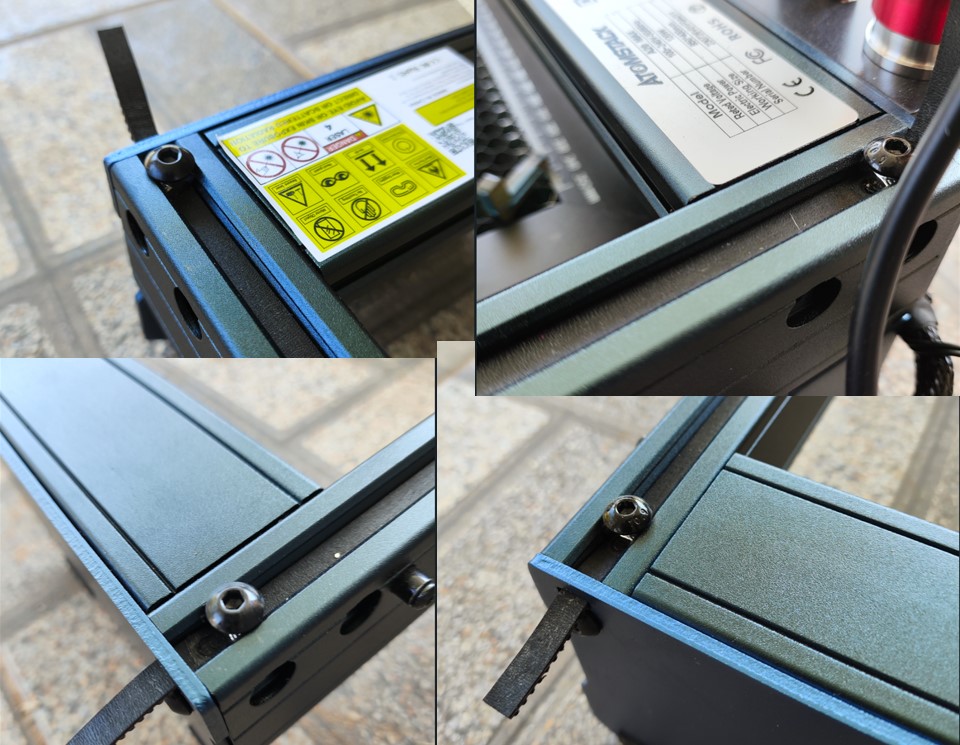
-I have cleaned up the rail and confirm there is no debris or any objects on the rubber rail that might hinder the smooth motion of the rail
-I use the genuine focus scaler to set the focal point,
-I need to carry the engraver hardware around every time I use it as my workshop is not fully ready yet, but no physical damage such as dropping, bumping the machine to something else etc
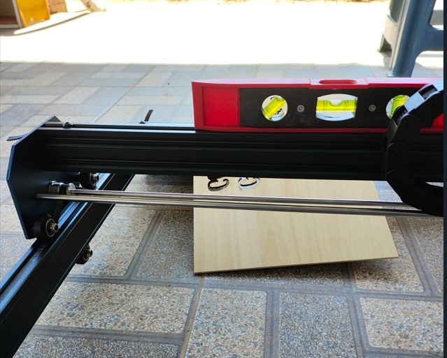
-I use the Honeycomb, the wood plate to engrave is firmly placed on Honeycomb with not bend

Could anyone help to locate potential solution for this, highly appreciated, Thank you in advance.

Best regards

Seems like this is an issue with your design since it is pretty consistent. Attach a copy of your file. One thing to check is the tension on your belts. With the power off tilt the machine up in the front and the Y carriage should slide slowly from front to back and not bang into the top of the machine. Tilt the machine up on the left and the X carriage should slide slowly across the X axis and not bang into the side of the machine. If it doesn’t do this the belts may be too tight.

Is your machine set to absolute position and the laser rotary is turned off. Does your machine home ok when you turn it on.

Try doing a test of just a circle and see what it looks like.

Just some thoughts but i still think it is your design.

There are some reference photos

Dear Loren Thank you for your advice,

Seems like this is an issue with your design since it is pretty consistent. Attach a copy of your file.

Alignement Issue.lbrn2 (149.8 KB)

The font is Google font, generally downloadable on Google site. I convert them to path, and weld them,
The font still looks like a complete line.

One thing to check is the tension on your belts. With the power off tilt the machine up in the front and the Y carriage should slide slowly from front to back and not bang into the top of the machine. Tilt the machine up on the left and the X carriage should slide slowly across the X axis and not bang into the side of the machine. If it doesn’t do this the belts may be too tight.

Yes, it does as you describe when I lift up one side around 30 degrees, both in X and Y direction, so I assume the tension is OK.

Is your machine set to absolute position and the laser rotary is turned off. Does your machine home ok when you turn it on.

It comes back to home position when turned on, Yes.
I use Absolute position, yes.

Try doing a test of just a circle and see what it looks like.
I found out that I cannot even make a simple circle, drawn on LightBURN

OK. So its not your file causing the problem. Couple of other things you can try.
Try these one at a time. And see if either fixes your circle issue. Sometimes they can cause issues
Open up Cuts/Layers under the Common tab and make sure Tabs/Bridges is turned off.
Then go to the Advanced tab and make sure everything under Pause Time is turned off And 0.0

Hi Loren,
It seems the settings are already as you adivesed,

I tried to change the tension of the belt, it slightly changes the output but it seems the result is random, I fear if I touch it too much it gets unrecoverable,

results are still the same,

I re-watched the installation (device/machine) video and everything seems to be alright,

I now tried LaserGBRL and the result seems OK,

Could it be potentially that Atomstack A20 Max is not compatible with the software? Or could this be a hardware issue that I might need to cotact the manufacturer?

regards

If it works with LaserGRBL then its not a hardware issue. I have an Atomstack X40 Pro which is basically the same machine but with a stronger laser so I don’t think its the machine. I’m kind of at a loss at this point. Couple more things you might try:

Your results may be symptomatic of a backlash problem** , a common hardware issue. In LightBurn, Optimization Settings, you can enable ‘Hide Backlash’, if the problem with the circles improves significantly then you definitely have a backlash issue

I have attached a small program called backlash.test. which should provide an easy method to help you identify and measure backlash. Turn off Optimize Cut Path and run the program.

BacklashTest.lbrn2 (166.1 KB)

The LaserGRBL test doesn’t look like a comparable test. Looks like that was done with horizontal scanning, not as a continuous line cut.

This is almost certainly a mechanical issue.

Check specifically that the pinion gears attached to the stepper motors are properly secured. The grub screw should be tight against the flat of the stepper shaft. Also review belt tension. They should be taught with no slack but not stretched. The laser module should glide smoothly to all corners of the machine with little effort.

There should be no noticeable slack in the chain of motion if you manually move the laser head by hand. Any slight movement at the head should immediately be imparted as motion to the belt and stepper motors.

Take caution to move the laser head slowly. The motion of the stepper motors will induce a current into the system.

I agree with all the above from berainlb. Recheck everything mechanically. Then if you don’t find anything try the backlash test i mentioned above. You already checked the belts so check if all the motor coupling set screws are tight and do everything else he said to do

Thnak you both Just a quick note I am at Asian time zone I will try your advice tomorrow and will report back again. Regards

I did some more adjustment,

  1. Assembly
    Check specifically that the pinion gears attached to the stepper motors are properly secured. The grub screw should be tight against the flat of the stepper shaft.

→ I found the 5mm shaft that connects the left/right pinion gears was moving wavy when I moved the X frame back and forth, I realized that the gurb screw needs quite a torque to firmly hold the shaft, I screwed it again tighter and now the shaft moves intact horizontally when moving.
It seems that the gap of circle is now smaller than before, but not fully firmly connected.

As to the belt, I pulled with possible max tension and gradually loosened it on Left/Right-Y and X axis, with the max tension the circle’s junction point’s gap was large, as I loosened the belt, the gap became smaller but at one point the belt got slack and cannot loosen further (gear does not interlock anymore), thus this solution did not fully solve the gap of circle.

  1. I also did some change in Backlash adujstment (as per the information on websearch, changing 200mm, 400mm, 600mm, 800mm speed’s setting value to + and -) for 0.1, -0.1, 0.5, -0.5, etc, so far there is no change.
    I fired the Loren’s file onto the woodplate and I saw around 1mm width difference on the vertical 2 lines, I might need to do some more experimentation on this setting.

Overall appearance of my device is uploaded for your reference, if you could have a quick look and see if there is any anormality, please adivise, highly appreciated.

This post might be hidden from the forum as it includes multiple external link I hope this post raches to you,

Best regards.

Disable Hide Backlash and retest. That shouldn’t cause what you’re seeing but I want to make sure nothing is affecting the outcome.

I suspect you still have backlash along the X.

Design a perfect circle and retest. Is the circle round?

Where are you doing this? Is this for the scanning offset?

I’d suggest deferring this until all mechanical backlash has been solved for.

Your frame is unusually wide. Make sure that the gantry is square to the frame. If you push the gantry up, do both sides reach the top limits at exactly the same time?

→ Yes, “Scanning Offset” tab, but I now disabled it, OK, I will leave it later.

Your frame is unusually wide. Make sure that the gantry is square to the frame. If you push the gantry up, do both sides reach the top limits at exactly the same time?

→ I am not sure if I understood your instruction correctly, I checked the 4 corners, and they seemed to be firmly assembled, level is also looking OK. All screws are fully tighten.


Disable Hide Backlash and retest. That shouldn’t cause what you’re seeing but I want to make sure nothing is affecting the outcome.

I suspect you still have backlash along the X.

Design a perfect circle and retest. Is the circle round?

Circle is a full round circle with 5 - 8 mm diameters,
please see the shot test result with backlash adjustment OFF,

Red square is the concern, it is still there. I found out that the line (laser) width of vertical and horizontal also differes, could this be a clue?

Thank you, I appreciate your advice.

(I’ll be offline for 2 hours from now)

Best regards.

The gantry is the overhead mechanism that makes up the X-axis and where the laser module is mounted. When you push the gantry up toward the top of the frame does it contact the left and right sides of the frame at the same time?

Asymmetry of laser dot is typical so not a complete surprise.

I see that some of the cirlces are actually circular. But others still show an issue. Does the problem only show occasionally?

Revisit X-axis mechanics. Are there any other joints other than between stepper motor shaft and gear? If not, double check the grub screw again. It’s very likely that there’s still some movement there.

Here’s another user with the same issue. His fix was to adjust the eccentric wheels

Here’s a video on how to adjust eccentric wheels. Done make them too tight. Just make sure there is no wobble on the X and Y axis

From what I remember of that Topic the issue was slightly different. The problem they were experiencing was distorted shapes. They were not experiencing disconnected circles.

Distorted shapes would point to belt tension or wheel tension issues.

I don’t think that’s what OP is experiencing.

Dear Berainlb,

The gantry is the overhead mechanism that makes up the X-axis and where the laser module is mounted. When you push the gantry up toward the top of the frame does it contact the left and right sides of the frame at the same time?

I found that indeed these were not aligned, so the gantry was like this (exaggerated):

I took following action:

But somehow, the circle still cannot be connected, I might futher adjusting around the belt tension (by not releasing the interlocking of the belt and the gear because they are now already optimal positioning)

Thank you Loren,
I remember there was a hex wrench was inside the packing, not sure to use for what because it was not described on the paper manual, but I will go now and try,
and will report back soon.

With the latest try with Loren’s input,
unfortunately it still happening that the circle is incomplete,

The hex nut seemed to be already optimal, no wobble,

to reply berainlb’s question,
it happens to the same position of the same shape no matter where I start,

This is the newest try (Ellipse):

The gap is getting minimized, but still not suitable for very accurate drawing or metal cutting (could be used for wood cutting,) I want to make a nice signboard for my wife’s restaurant, I hope I can clear this issue soon,
I will try adjust the belt again, Thank you for your adice anyway, it is really helpful and if you have any further idea, that will of course greatly be appreciated,

Thank you again.

I dont think you need to loosen the belts. Just move the gantry all the way forward and make sure both sides are touching the front plate then adjust the eccentric screw so there is no wobble. Then see if there is any wobble in the x axis and adjust the eccentric screw as necessary. Dont make them too tight, just tight enough to eliminate any slop