Good morning wise people. I’m new to the world of Laser Cutting and new to this Forum. I may have bitten more than i can chew, so to speak as i have upgraded my machine from its Leetro Controller to a Ruida RDC6442S. The upgrade seemed to go ok until i tested the homing of the Laser Head. Home is rear right where i have limit switched on both X and Y axis. My issue is when i turn the machine on and it attempts to home the machine hits the Limit Switch and appears to carry on making a dreadful noise in the process. It finally stops after 10 or so seconds almost as if the machine has timed out.
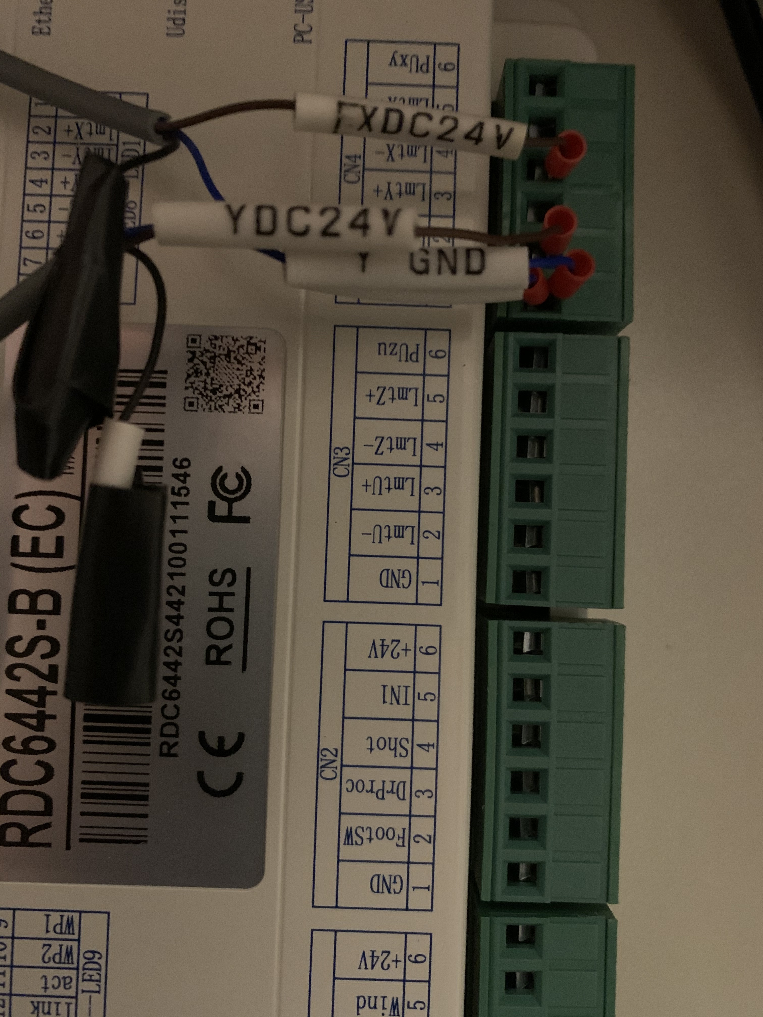
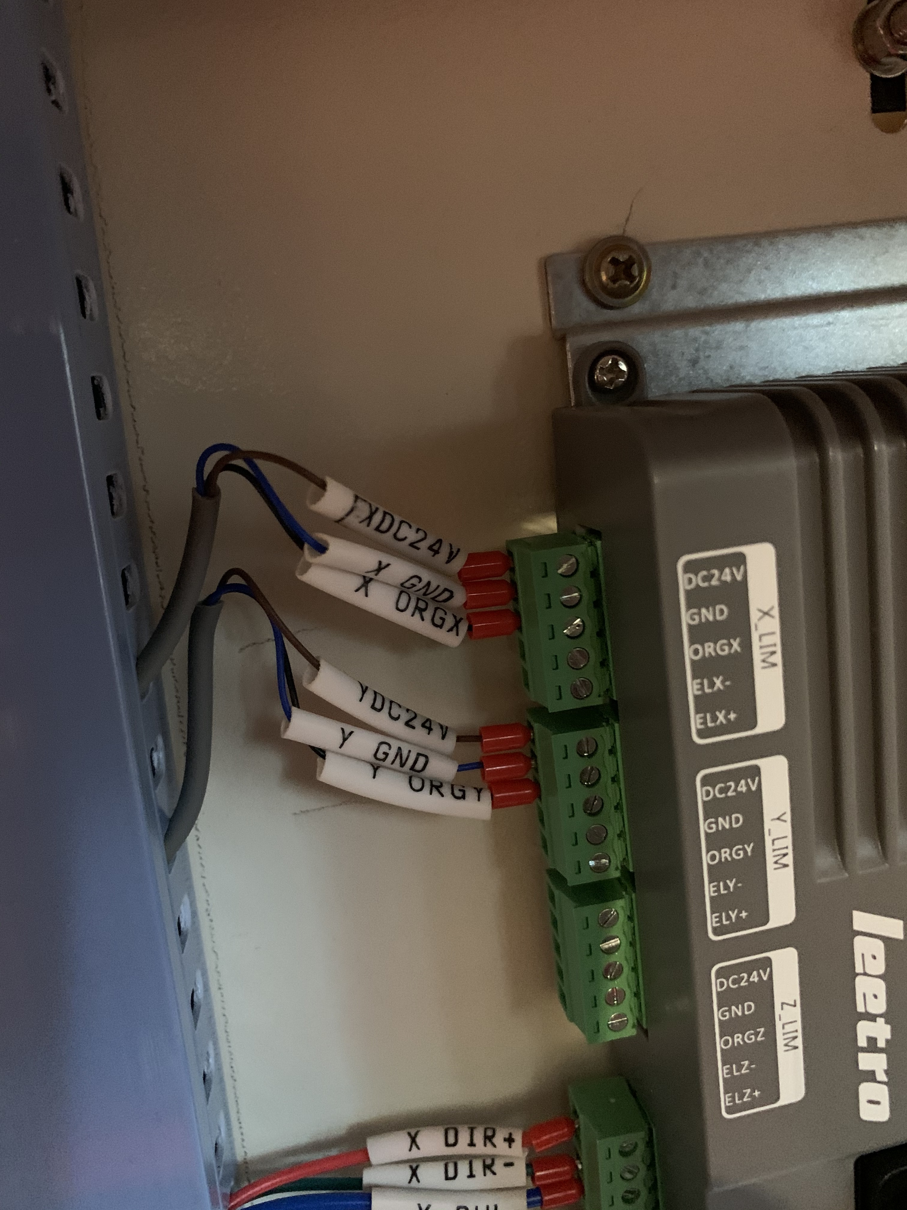
Now, Im no electrician and there are no clear and simple wiring diagrams out therefor people like me. On the Leetro there were 3 wires for each limit switch - X/Y DC24, X/Y GRD and X/Y ORG. The information I have suggests that only two of the connections are required which Im now thinking is incorrect. Ive (hopefully) attached two photos, the original config and the new config. Thank you so much in advance for any help you can provide, it really is appreciated.
If you have the little square electronic limit switches, they are three wire, +, -, and signal.
If you have mechanical limit switches, they are only two wire. I believe that would be signal and -, but double check.
In your diagnostics screen on your controller you can test your switches no matter what type you have. Manually press the switch for the mechanical ones, and put a wrench or something on the electronic ones. Most electronic ones also have a built in LED so you can see if they are wired and are tripping, but only the diagnostic screen will tell you if you have them wired to the controller correctly. That will also tell you if you have a broken wire between the switch and the controller. Had that happen, the LED on the switch came on, but no indicator on the controller diagnostic screen.
Something to be aware of (that may not be overly obvious):
The way Ruida labels the connections for limit switches can be confusing. For example, Z+ and Z- represent the direction of limit (not electrical polarity) in either the upward or downward increment. The same applies to X, Y, and U.
Thanks for the reply Stroonzo, I managed to resolve it by rewiring…
The 2 brown 24v for X and Y need to connect together and to the output puxy on Ruida,
The two black wires I had taped go to x- and y- respectively.
And the GND appeared to be correct.
Everything appears to work as it should. Just need to sort out the job origin which irrespective of where I start the laser head moves back home. Just a tad annoying!!