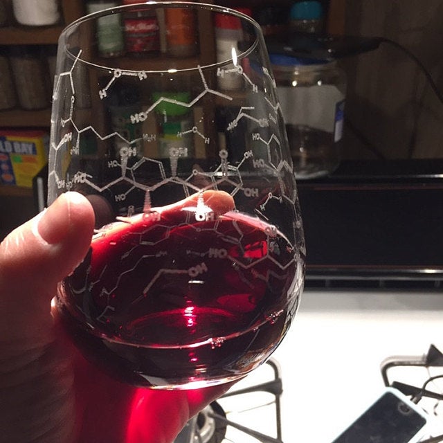
I am trying to migrate some files that I’ve previously used in CorelDraw on an Epilog Zing onto Lightburn and my Boss laser. In the current design, I’m using something where I have created chemical structures using a program called ChemDraw and have used the raster setting (vs vector) in the previous software setup. I’m wondering if there is a fundamental difference in how these things are handled in the Epilog driver vs. LightBurn. This is the product that I have made before without issue on an Epilog:
In my current predicament, whereas I have been thinking that this would be all done via raster, I see that raster is only done when an image is brought in. My chemical structures (below) area series of lines and letters. LightBurn interprets these truly as lines, and seems to expect this.
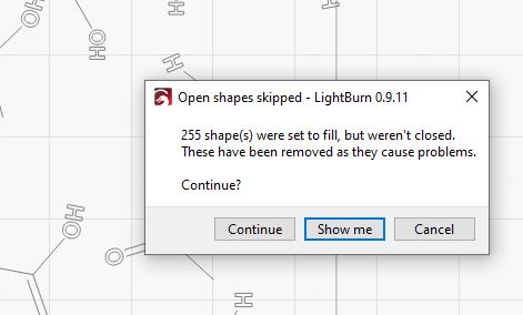
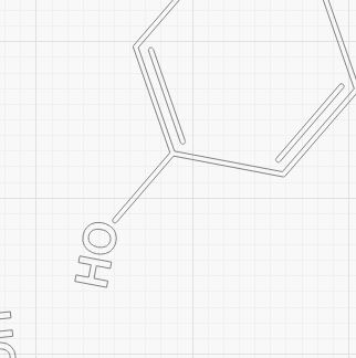
I also see the “outline” of the letters, but there is no visible fill. Point being, if I set the layer to “FILL”, it doesn’t like my lines, saying they should be filled:
…and if I set it to “LINE” (which I am hesitant to do on glass), it seems as though I may get the lines of the chemical structure, but my letters aren’t filled in. I can’t find a way to get what I have easily been doing on the other platform.
Again, maybe there’s a fundamental difference in what I’m asking the software to do, but I feel I need to better understand this. Maybe I just need to find a better way to import things into LB…but right now I’m quite frustrated with just trying to transition existing designs onto a new platform… Any help would be appreciated.
We can help. But this may take me a few posts so hang in with the edits for a bit here.
Due to this design, you have a few things to consider. All you “text” should be closed shapes and placed on their own ‘Fill’ layer to have them look as you desire. The ‘Open shapes’ message is telling you that there are shapes set to ‘Fill’ that are not closed. Select the ‘Show me’ button and look at what has been selected. If your text is selected in addition to all the lines we will need to deal with that. Select the text and then “ALT-J” to Auto-Join selected shapes to close this text. Then set that to a ‘Fill’ layer.
Then select ‘Preview’ (TV screen icon near top-center) to preview these results. Let me know how this goes and we can go from there.
Second, your concern is valid about using ‘Line’ cuts with your glass, this should be tested for speed and power settings to ensure the desired result. Boss Laser has a list of starting points for settings on their site, with different values for different wattage machines: https://www.bosslaser.com/laser-settings
You can use Edit, Select Open Shapes set to Fill to highlight the problem areas. It’s also possible that Edit, Auto-Join selected shapes will help clean things up. Switching to Node Edit mode may show you locations that should be a single node but are really two or more very close together.
Rick, thanks for your reply. I think I may be narrowing in on the issue here. When I’ve drawn the structures preciously in ChemDraw, like any chemistry modeling software, you can select the line width for the bonds. (for example, if you are making a large poster for a scientific conference, you would make them thicker as opposed to in a manuscript.). All that said, when I have them imported into CorelDraw, the line thickness stays as intended. I have used this all on the same layer, engraving on an Epilog with no problems in the past.
Here is a look at the image in Corel zoomed in, and you can see that the lines (bonds) have a width, and that they get larger when one zooms in more:
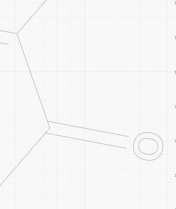
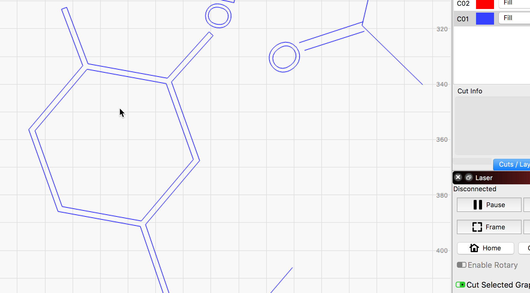
However…when I move this design from CorelDraw into LightBurn, I’m thinking there is something going on with how it translates after the import, because it completely ignores bond widths, and treats these as absolute hairlines. I can zoom in to the max, and my widths remain infinitesimally narrow.
So from this perspective, I can see why LightBurn acts the way that it does…it thinks these are lines, and therefore doesn’t want to “fill” them. I can recreate this behavior on CorelDraw if I set it to “hairline”, which is what one would do for vector cutting.
All this said…I think I’m still confused as to why these two pieces of software interpret the same thing differently. Is there not some way to import differently, or otherwise communicate to LB that these are essentially lines that have a defined thickness? I am willing to rebuild this design piece-by-piece if I have to (I surely hope not!) but this does not seem to be an endeavor that should be taxing any capabilities…I think there just must be some fundamental difference that I have yet to figure out. Thanks again for all of your help!
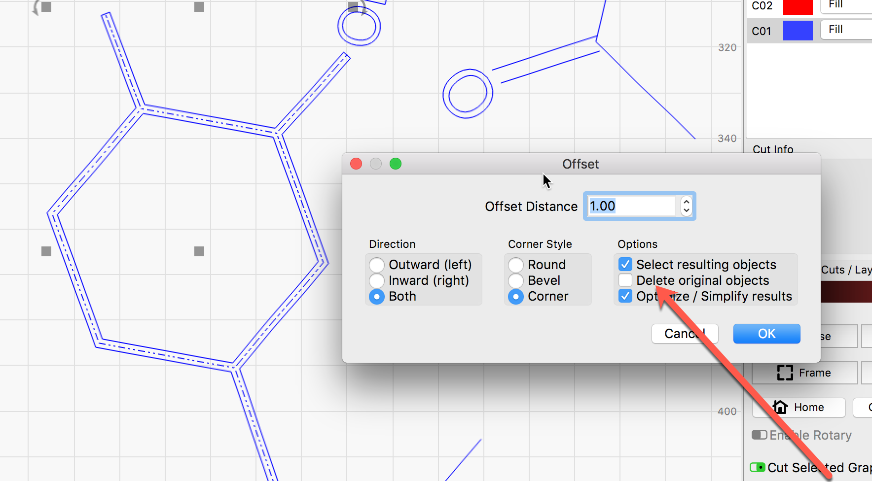
Your observations are spot on. LightBurn does not import line width or fill settings as you see, but you can make the current are work with a few clicks.
Let me grab some images…
Ok, so here is an example of using the ‘Offset’ tool to “thicken” a line for scan filling.
Update - Mining through the forum, I’m seeing another very similar post, but I’ don’t know how to link to it herein, but the title was “Importing from CorelDraw”, also with a "line width corrected to a single line issue. I’m going to try some of the maneuvers suggested there, but it sure would be great to find out what his final solution wound up being.
Can you select the lines in CorelDraw and do a “convert to path” on them?
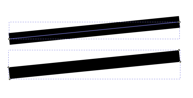
Here’s 2 lines drawn in Inkscape. The top one is just a line with a stroke thickness of 0.2". You see it just has 2 nodes. Lightburn will just ignore the thickness and treat it as a zero width line between the 2 nodes.
The bottom is the same line but “converted to path”. You see it now has 4 nodes, one at each corner of the now non-zero thickness line. Now Lightburn can fill that area between the 4 nodes to give it the correct thickness.
So if you can select your lines and "convert them to a path, that will probably get you where you need to go.
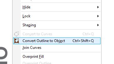
I got it!! There was no such thing called “convert to path”, but there is a “convert to curves”, which I’ve used in the past when I wanted to make letters a vector as opposed to a font…but this also didn’t help.
What it wound up being is a usually-greyed-out setting called “Convert Outline to Object”:
The only way that I was able to get this to work was having to ungroup everything, and then and only then would this setting become available. Then I was able to convert outline to object, saved, and exported to LightBurn:
When I go into preview, the nasty fill error is now gone!
Thank you to everyone who has replied. Now on to the real work on this project…actually etching it for the first time on this laser.