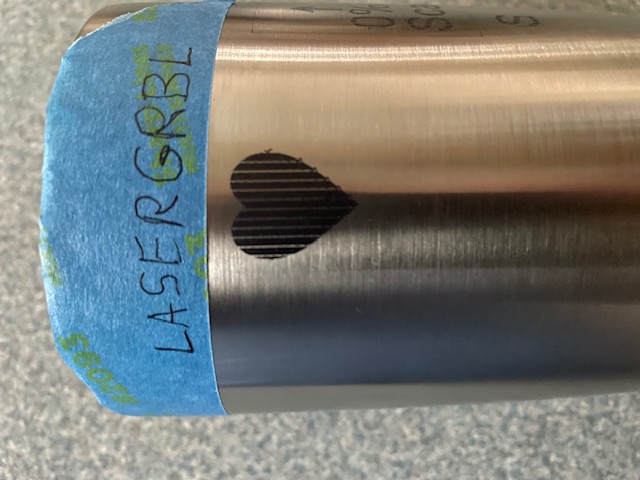
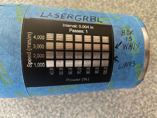
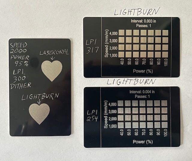
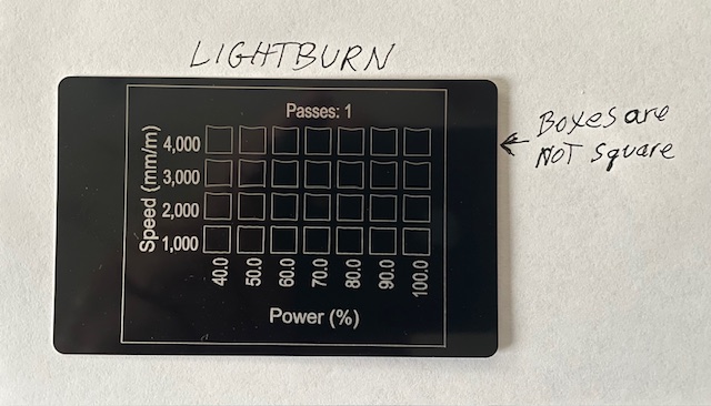
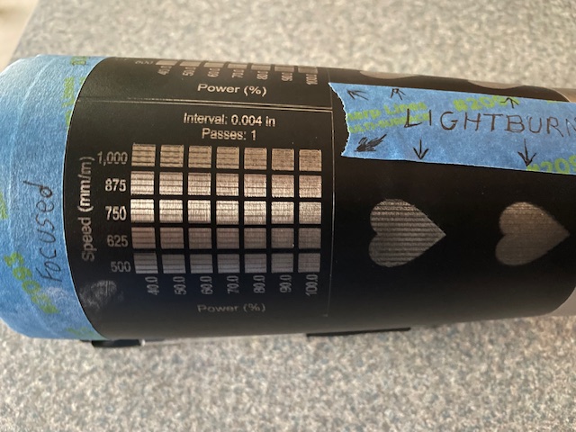
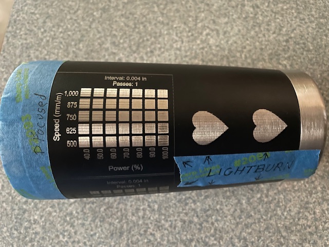
I ran some more test today with laserGRBL and with lightburn. I’m still getting lines with both programs on the rotary chuck. With out the chuck the lines are almost comletely gone unless you have a magnifying glass, But the edges of the materials test grid boxes have waves in them. Here are some more photos.
I have to go, I’ll look the rest of your post over later, but wavy lines look like too much speed, not enough overscan, or a loose component.
Questions add to list:
When you hit test do you get 1 full rotation of the chuck?
When you change to flat, are you sure you are turning off the rotary?
When you unplug your Y and plug the rotary in, do you power off the machine first?
I respectfully disagree about not changing scan angle on a rotary. I am NOT a guru or a developer, but on my set up I get much better results engraving on a 90 degree angle than I get on a 0 degree angle.
I am on a 5w diode with a rotary chuck. At 0 degree angle I get a corduroy texture. At 90 degree I get a smooth surface.
A chuck is a different story With a chuck you don’t have slipping of the objects, so the scan angle doesn’t matter. The advice not to change the scan angle is for rotaries, not chucks.
Your main issue seems to be only really be showing at the rotary (the skipped lines), which appear to be regular despite changing line interval or scan angle - is the interval of the problem the same as gear gogs/belt teeth at the rotary?
The other pic (IMG_1669) on the flat with the ‘boxes not square’ and where you labelled the ‘Box is wavy’, is possible a secondary or downstream issue since it also seems to appear at the rotary (IMG_1664), so you may want to check the laser module - mount/head assembly/optics, for any looseness that might contribute to a front-back wobble.
It might be useful if you ran this backlash test program (on the flat): Backlash.lbrn2 (73.5 KB)
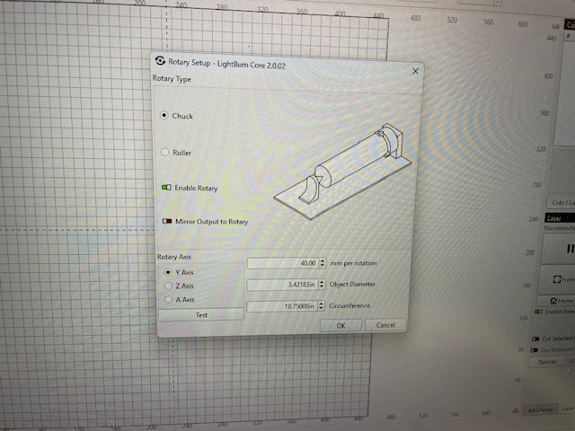
Try running the Test on the Chuck. The Chuck should make one complete rotation, then reverse direction and end up where it started. If this doesn’t come out right then change your mm/rotation till it does. I take a magic marker and make a little mark on top of the rotating part of the chuck so i know where it started.
Yes when I push test on the rotary set up page I get 1 full rotation 390*. I have also created a 4 inch line in lightburn and had the rotary engrave it. The rotary produced a perfect 4 inch line
Yes I am turning the rotary off.
I am powering the machine off.
I spaced out that there are no splits in grbl laser rotaries until looking at OP’s rotary setup window and thinking it through. So what I thought what looked like a split issue is something else. Hopefully someone else can be of more help.
Following Along!