I have an Raspberry Pi connected to my MKS Sbase v1.3 on my K40 running LinuxCNC and just finished getting “spindle” control working then found out LightBurn is using M106 for laser control?
Can anyone explain this? It can make for an interesting system where one is both using the machine spindle AND a laser but I don’t think that would be the norm.
This was brought up earlier and was closed with no comment.
I might be moving towards the answer… I tried to engrave with the Sxxx command for laser control and LinuxCNC moves at a snails pace. I removed all the Sxxxx commands from every line and it moves far faster.
Trying to figure this one on the LinuxCNC irc channel but like many graybeard irc channels the topic ends up going down rabbithole after rabbithole… ugh.
Hi, @DougL I got a question for you, by “S” commands are you referring to spindle power like “m106 s1000”. So if I’m understanding you correctly your saying you removed the “s” variable from the M106
at each occurence. When you say every line does that mean each “G1” move set the “S” again? or that you removed it for each new cut?
if you use LIghtBurn to generate GCode for smoothie or GRBL and probably others you get something like
G90
X150Y150F12000
G91
M3
X-0.1S255.0
X-0.1S300.5
X-0.1S450.7
X-0.1S105.2
…
g90 sets the exact position
g91 puts it in relative moves mode
m3 enables the spindle
I hope you know what the X commands do and they also include the raster laser power level in the Sxxx.xxx value.
In CNC machining, where GCode originated it’s all about spindles so there’s M3, M4 and M5 commands along with the “S” command
When LightBurn is setup for a LinuxCNC post processor(machine type is LinuxCNC) then the GCode
is like this:
G90
X150Y150F12000
G91
M3
X-0.1
M106 S255.0
X-0.1
M106 S300.5
X-0.1
M106 S450.7
X-0.1
M106 S105.2
…
M106 is not a GCode standard by LinuxCNC will let you define custom M codes as python scripts.
I just don’t see this being very efficient or fast when a python call is made for every line in the file and a raster engraving will have thousands when the resolution is 0.1mm at 254 DPI.
I see, I have never and will most likely not ever use Linuxcnc myself so in that regard I can offer no assistance, as M106 carried no weight in my current gcode vocabulary, never heard of it till your post actually haha. I went the route of Arduino uno with grbl 1.1h for both my homemade co2 laser and plasma table. On my plasma table, I do have to edit lightburns gcode output after the fact though which can be a pain in the butt, but it’s cheaper than sheetcam for now.
This is a sample of lightburns gcode output to fill a 1x1 square, looks like it still makes heavy use of “S” definitly not as much as lightburns linuxcnc output for sure.
It seems it definitely does reference the power setting a heck of a lot. Sorry I can’t be of assistance when it comes to Linuxcnc. Best of luck figuring out your machine. I think I know as well or better than most how hard it can be since I’m the only tech support for my machines.
-Alex
I too would be interested in getting this to work properly using Linuxcnc (didn’t even know it was a possible ‘machine’ in Lightburn), so I can use my JTech laser on my cnc. Have tried using other software to create laser toolpaths, but they don’t run smoothly in a raster format.
I’m still working on it but so far it seems that the use of spindle setting, via Sxxx, greatly effects the performance of the motion planner output as properly regulated spindle speed is critical to CNC subtractive machining. Currently I’ve done a search and replace of the “M106 S” commands with the following:
“M106 S0” → M68 E0 Q0"
“M106 S” → M67 E0 Q"
And the output will be on motion.analog-out-00
and the results are looking to be useful.
thanks, I see they are using M68 E0 Q0 for laser off and M67 E0 Qxxxx for laser on/power settings and I’d found on a LinuxCNC forum someone mentioned that. Thx. I also see they did a G4 P4 so will have to investigate that. Well, G4 is a dwell setting/pause so I will try adding a G4 P0 to disable any possible default dwell/pause being able to effect performance.
Update on where I ended up. the M106 command was too time consuming running python script for every pixel at 254DPI( ie every .1mm of the image) of an engraving. What I found was the M67 command seems to work quite well. But it has to be on the same line as the motion.
ie NOT this:
X-0.1
M67 E0 Q25.8
THIS:
X-0.1M67 E0 Q25.8
Currently, to get to this I have to setup my LinuxCNC machine definition for GRBL post processor because it gives me lines like this:
X-0.1S25.8
So I have a script to post-process the G-Code using 2 Sed commands:
sed -i s/‘S0’/‘M67 E0 Q0’/g $BASE_NAME_NEW
sed -i s/‘S’/‘M67 E0 Q’/g $BASE_NAME_NEW
but I need to clean that up as it will change comments with just a capital “S” in the comment.
Previously, the parsing was effecting the motion performance doing .1mm dots even at 5% power level.
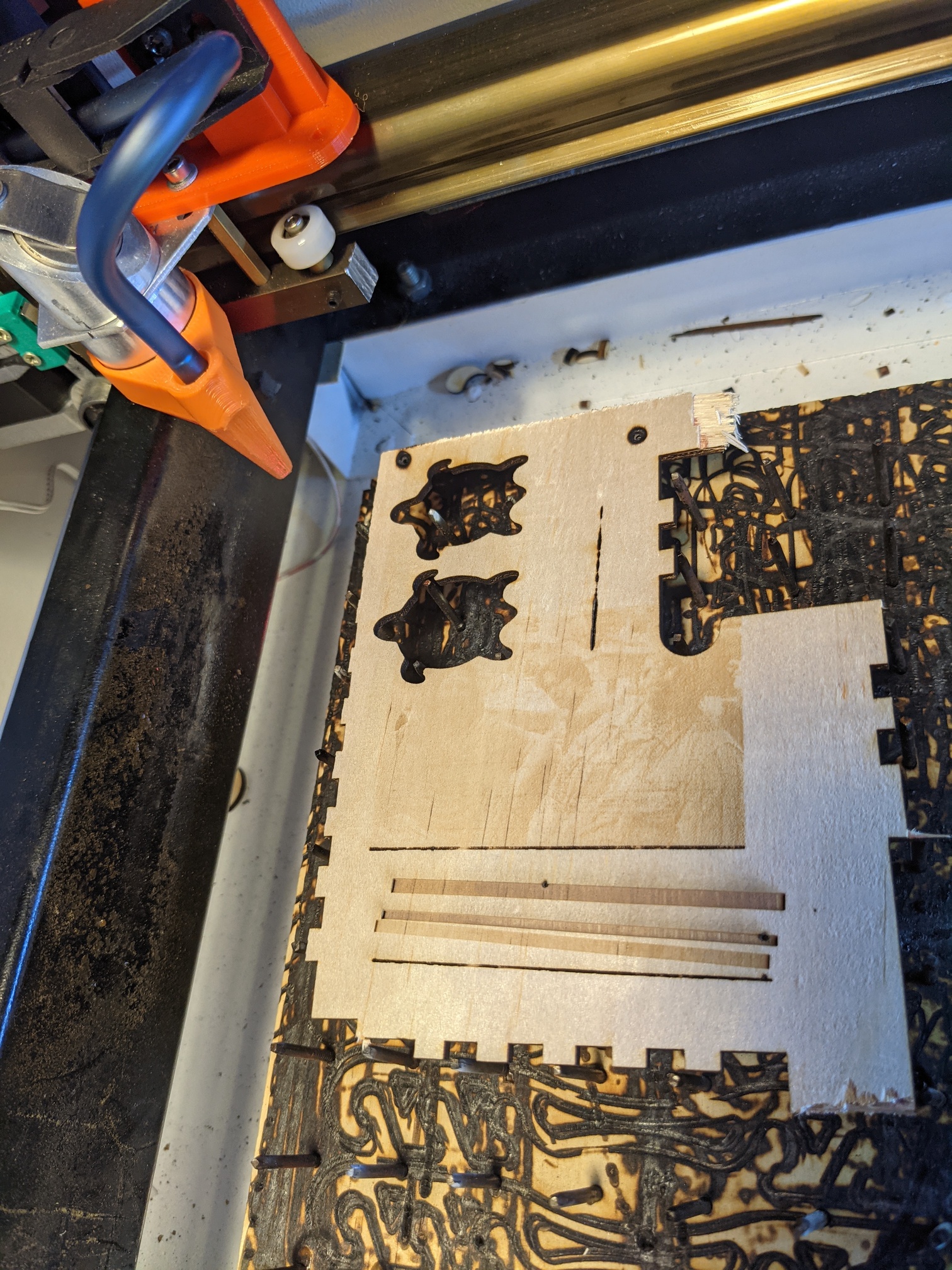
I recent test using just the M67 command resulted in good engraving motion speed and I can see Donny and Walter so it is working.
Here is the original to help you see those characters in the engraving.
I will test changing the PWM frequency to see how it effects engraving and then I will test grayscale.
This image was at 5KHz PWM Dithering and 5% power level on a 4 year old K40 with original tube/LPS.