Looking for a finger joint style box making software - doesn’t have to be free, but I cannot justify paying $19/month or $180/year to use cuttle without the free limitations… even though it’s much better than the only other one’s I’m finding: makercase and boxes py, neither of which work for me…
What I need, in order of most important to least important:
full control of all dimensions including: material thickness, and finger size - both of which are problematic with makercase
can run fingers full length of box - problem with cuttle makercase boxes py
ability to easily switch between (and even mix) mm & inches - boxes py only has mm as best I can tell…
outputs to svg or lightburn
preferably with separate X axis and Y axis kerf corrections
Sounds to me that you need to learn how to do it manually yourself. It’s not that difficult. Hobo with Wood just did a couple videos outlining the process.
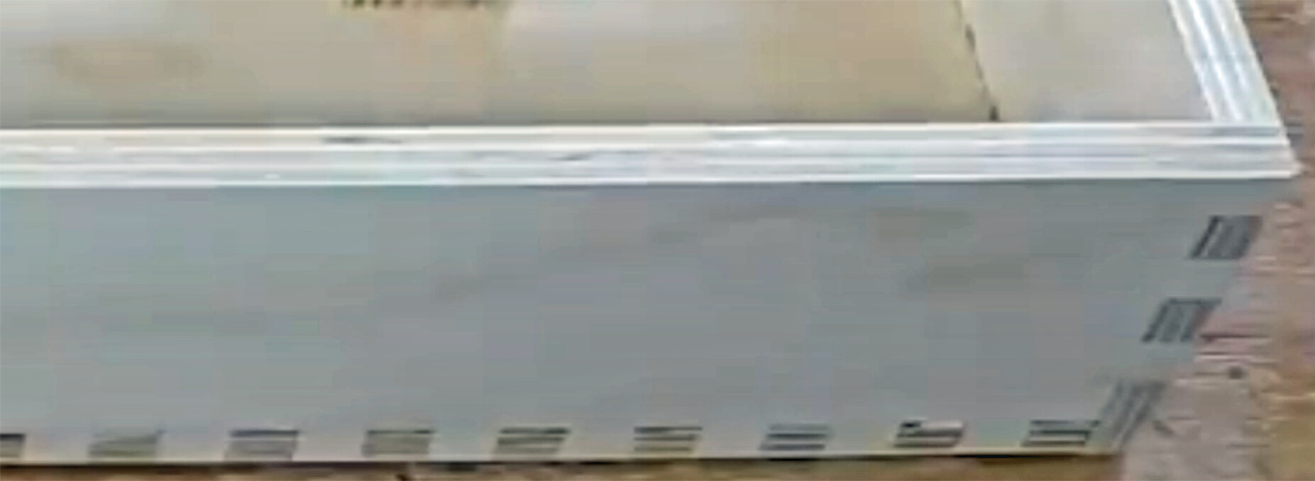
I use boxes from this one.
2.8mm Baltic ply
No width corrections in Bixes.py
No kerf setting in Lightburn
Slots in Lightburn are 3.0mm wide
Tabs fit in slots perfectly for a snug fit
10w laser
Why do these applications not work for you? “Does not work…” is not much help.
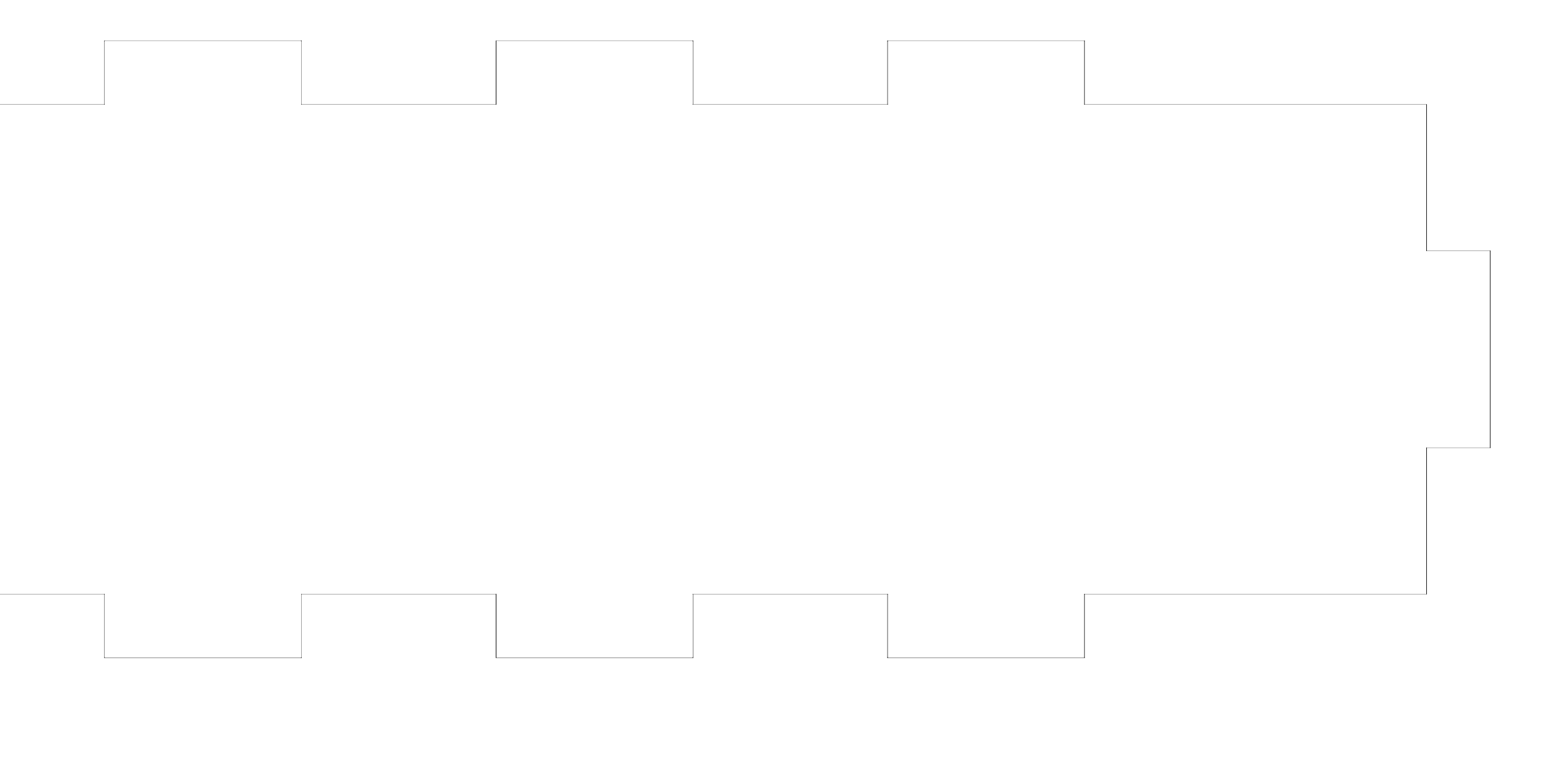
I already outlined what problems I was having with which programs in my requirements… one I didn’t mention is that with boxes py the output file is missing lines as seen below:
Of course, this one was done on a table saw, with the finger joints cut to come out evenly.
And YES, I can draw out the box in Lightburn freehand, calculating the necessary kerf correction & all… but there’s about a 100x time factor involved vs doing it in software that automatically does these things for you. In fact, I could probably cut out a complete box on my table saw in less time than it would take to draw out the box in Lightburn…
To elaborate a little more, in makercase it limits the material thickness based on the box size. If I want a finger jointed box with interior dimensions of 1.5"w x 4.5"l x 1.5"h and I want to make it out of 3/4" maple that will later be shaped and engraved, makercase tells me “maximum thickness is 0.366”
in this captured (or supported) finger box, ideally there should be 4 & 3 fingers instead of 3 & 2… I can fix that in Lightburn, but I shouldn’t really have to.
Just a suggestion, but if you wanted to learn how to create your own box template in Cuttle, you should be able to do it. If you need help creating one that fits your needs, check out their discord channel and leave a message.
Or, check out their Facebook page and describe what you are looking for. They do a live video every Thursday where they go step by step in creating a template. Maybe they would do one for you.
I collected a list of all generators I came across so far, I don’t know if one of them fulfills your requirements, but you might check: Links and Media - Diode Laser Wiki There are at least two or three generators that were not mentioned here yet.
It sounds to me that what you need is parametric CAD. This should satisfy all your requirements, including different kerf allowances for X and Y axes, (except maybe output to SVG and/or LightBurn). The main applications that I use are SolidWorks and Fusion. I’m lucky enough to have access to SolidWorks for my day job but I still pay for Fusion for most of my personal projects. FreeCAD is another parametric CAD program that you might like to try. It’s not as user friendly as SW or Fusion but it is totally free. There’s a free tier of Fusion for personal use and a low cost version of SW for makers as well but they’re both restricted in terms of functionality.
Seems to me that at least part of the listed issues with boxes.py may be due to unfamiliarity with the options.
Review “surroundingspaces” option in “Settings for Finger Joints” section and reduce the value. This should allow you to eliminate any edge gaps.
This looks like you’ve added an unusually large “tabs” value in “Default Settings” section. This is likely not what you want. Reduce to 0 to eliminate this or a much smaller value if you indeed want holding tabs.
This leaves the following issues:
inches vs mm - not immediately addressed. You could modify the source to do this if you were so inclined.
asymmetric kerf - I have never seen a generator or even a generalized application that allows for asymmetric kerf so may be a difficult requirement to fill. Even designing for this manually would be a bit of a pain and non-trivial.
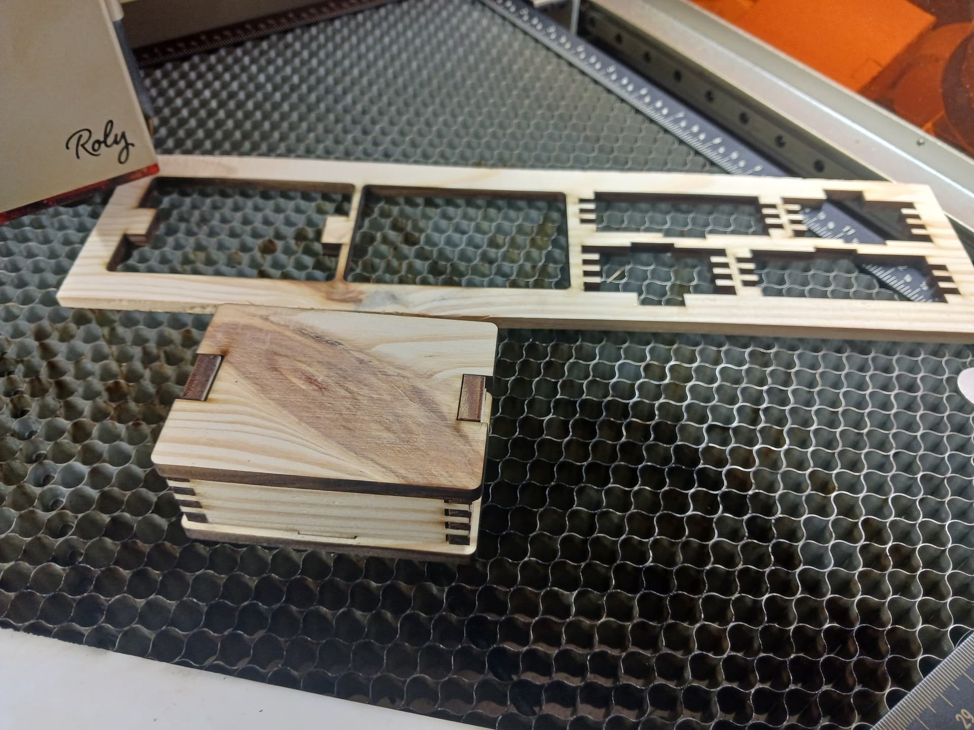
I like to make useful little finger-jointed boxes using laser and Lightburn… from thin bandsawn planks from small tree branches and scraps of construction lumber.
I start by using Boxes.py or MakeABox.io (and others I’m sure) to make an appropriately-sized generic six-sided box with lots of fingers (usually related to thickness) running along all edges. I also apply kerf correction here… and zero out the kerf settings in Lightburn. I usually use 0.12mm or 0.13mm for a nice fit.
Import the SVG, PDF, or whatever into Lightburn and use the node editor to adjust the fingers and tabs to suit the design I’m looking for. This can go pretty quickly by simply box selecting and deleting/moving nodes or groups of nodes to form new tabs/fingers to suit… leftmost box design (below) as imported into Lightburn and rightmost group is partially adjusted using the node editor.
Once satisfied with the result, place material on the laser bed and laser the result. Here I’ve used a 45-degree orientation of material to compensate for the difference in X and Y kerf… but depending on your laser you may get satisfactory results without the 45-degree adjustment.
WOW! That’s a nice resource misken added to my bookmarks
David: The 45degree thing is a nice idea! Unfortunately, it’s also kind of the downfall of my Atomstack X7 Pro… multi-axis / diagonal movements are not very accurate, and often result in jagged lines I’ve changed out the drive belts and tightened them as tight as I can get them. It increased the speed I can engrave on multi-axes from about 120mm/min to about 280mm/min without jagged lines showing up… this would result in hours to cut out the boxes instead of minutes. So, until I can get a better laser cutter/engraver, I’ll just have to set the output file for the X axis kerf then manually edit the file to adjust the Y axis kerf.
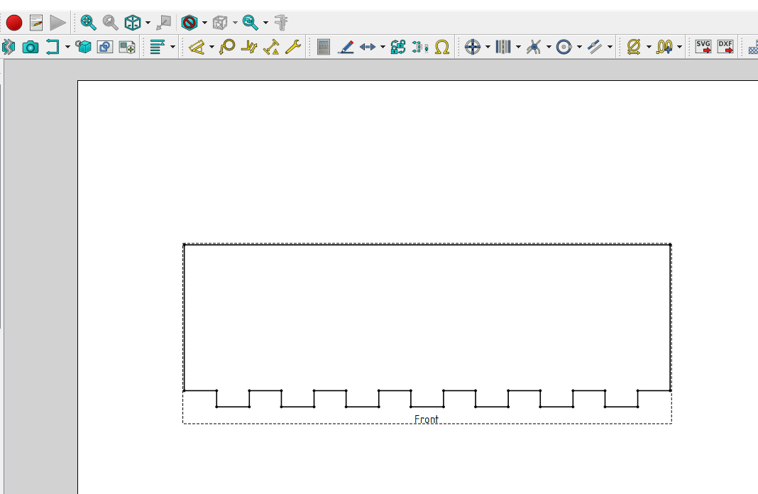
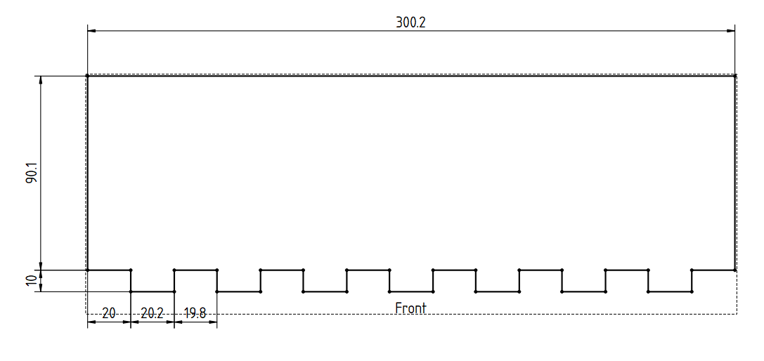
Further to my earlier reply, I’ve knocked up a very simple example in FreeCAD (which I’m not very familiar with at all!). The model is driven from an internal spreadsheet where the various parameters can be entered. These drive the solid model which in turn updates the 2D tech drawing. This can then be exported as SVG, DXF or PDF. This enables you to have different X and Y kerf values.
If you need a different size or number of tabs you just enter the new values into the spreadsheet and the model and the drawing will update automatically.
Let me know if you want my example file to use as a reference.
Obviously this is a very simple design with only single axis movements (no angles or curves) and it would be more difficult (and in some cases impossible) if it contained such elements. I don’t think I’ve missed anything obvious but I’m sure you’ll let me know if you find anything amiss!