i did some interval testing on my Atomstack A5 module. Everything went fine but suddenly lines started overlapping and it looked like steps were lost. I’ve already tried to tighten the belt for the axis movement but there is nothing changing. The strange thing is that there is a difference if im scanning bi directional or not. I have two pictures. The first shows 5 lines with normal scan. The other one shows 5 lines with bi directional scanning activated. I dont know why this is happening since i didn’t change anything on the machine settings.
These type of issues are almost always mechanical.
You’re not showing the whole line so not sure necessarily what’s going on at the ends. There may be some additional clues there.
Can I assume that the lines that you’re showing were burned on the X-axis?
In any case go through the usual suspects for mechanical issues:
double check belts - there should be no slack in any of the belts. They need to be taught but not stretched. There is a danger of overtensioning although that doesn’t necessarily look like the problem here. Make sure the belts are free of damage.
check pulleys - make sure the pulleys are not slipping on the stepper shaft. Check that the grub screw is secured against the flat portion of the shaft. Check for damage on the teeth of the pulleys.
wheel to rail gap - make sure there is no gap between the wheels and the rails. There should not be significant play laterally. Adjust with eccentric nuts that are situated between the wheel and the plate if required. Again, do not overtighten. Check that wheels are not damaged or distorted in any way.
make sure rails are clean and free of obstructions. Check for damage that would affect travel.
In the end the laser head should be able to move freely, easily, and smoothly to all corners of the laser. There should not be any noticeable slop or looseness as you change directions.
One thing from a setting perspective that could be causing lost steps is if you are trying to go too fast or acceleration is too high. Acceleration should not be a problem as long as you’ve not changed any GRBL configurations. If speeds are reasonable but symptoms are improved with further slowing down, then that hints to a mechanical issue. If speeds are excessive and are remedied by going to reasonable speeds then you were just going too fast.
Take a walkthrough of your laser and let us know how it goes.
So normally i would agree with the mechanical issue but i just can’t understand why its engraving correctly when scanning in one direction and from the moment where i activate bi directional scanning it starts to give me this failure.
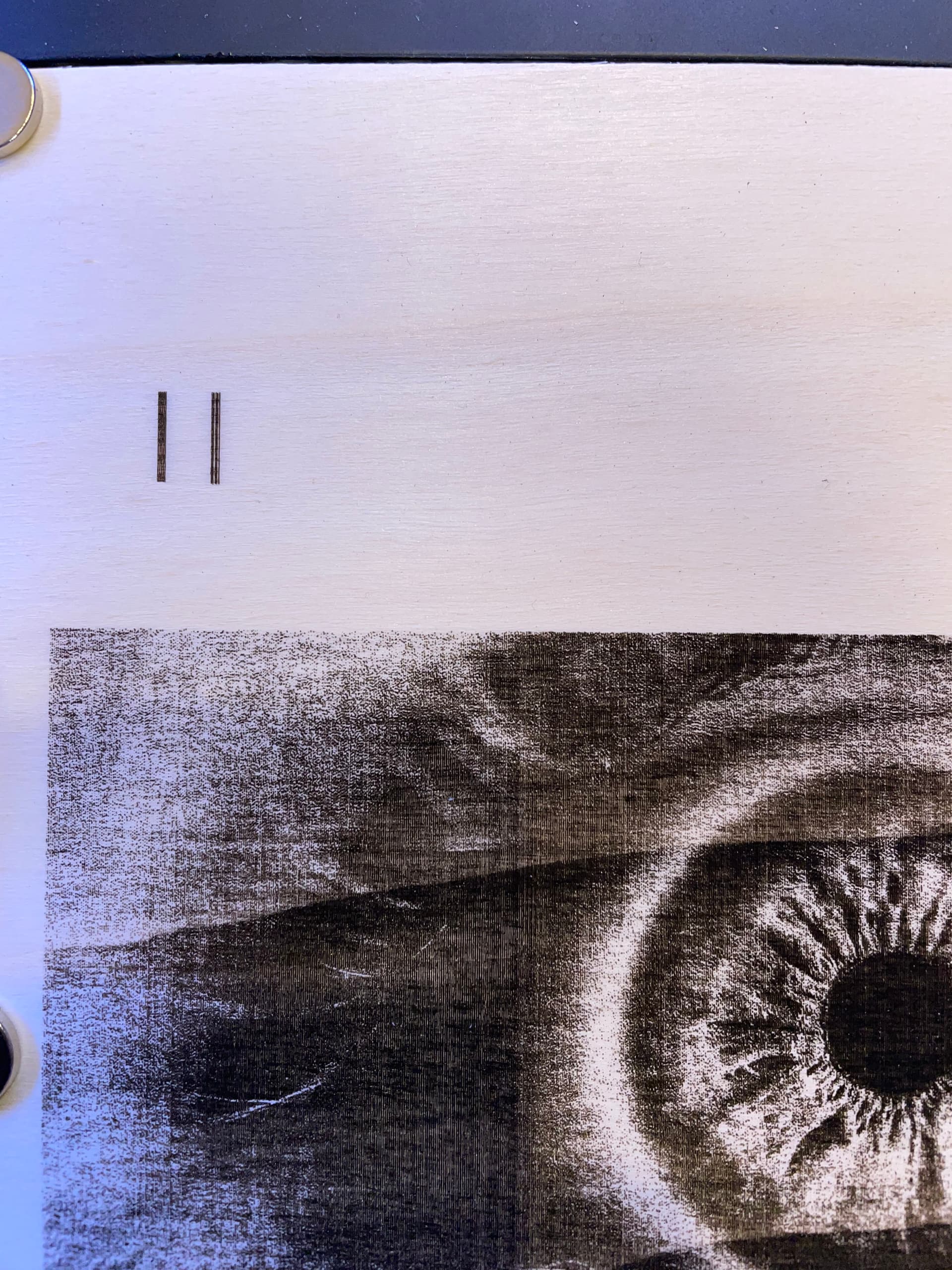
I’ve decided to engrave a test photo with bi directional scanning off and on and what should i say… while photo engraving this problem doesnt occur.
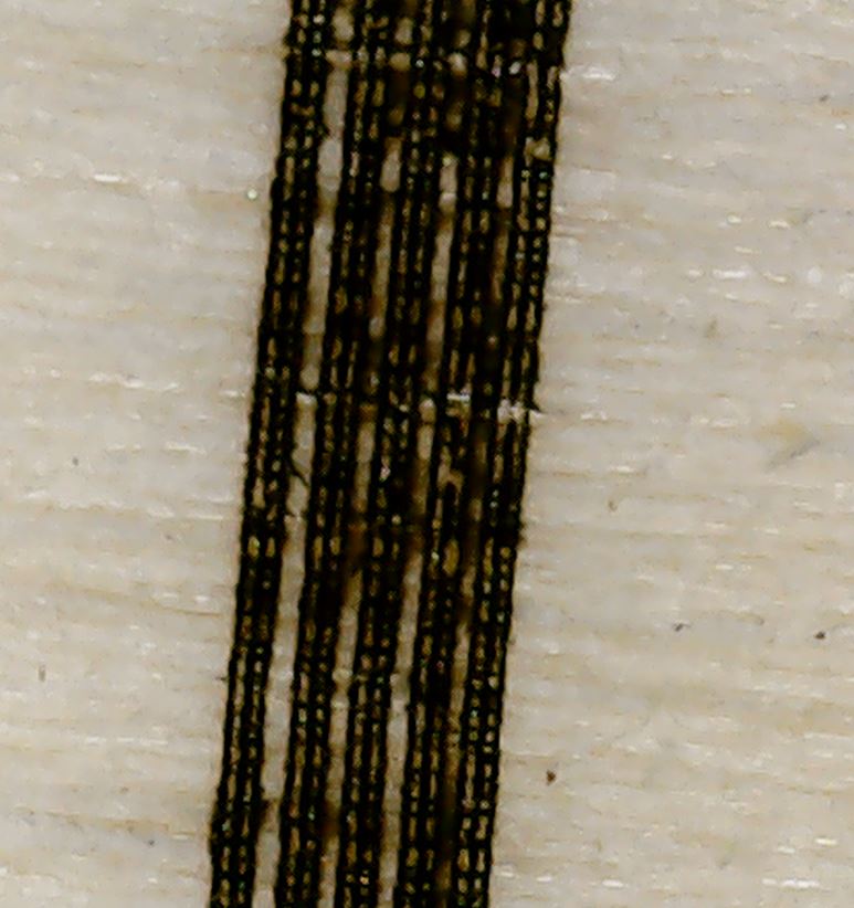
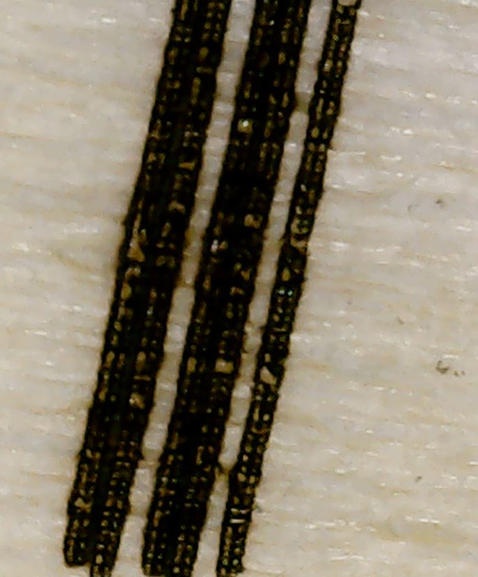
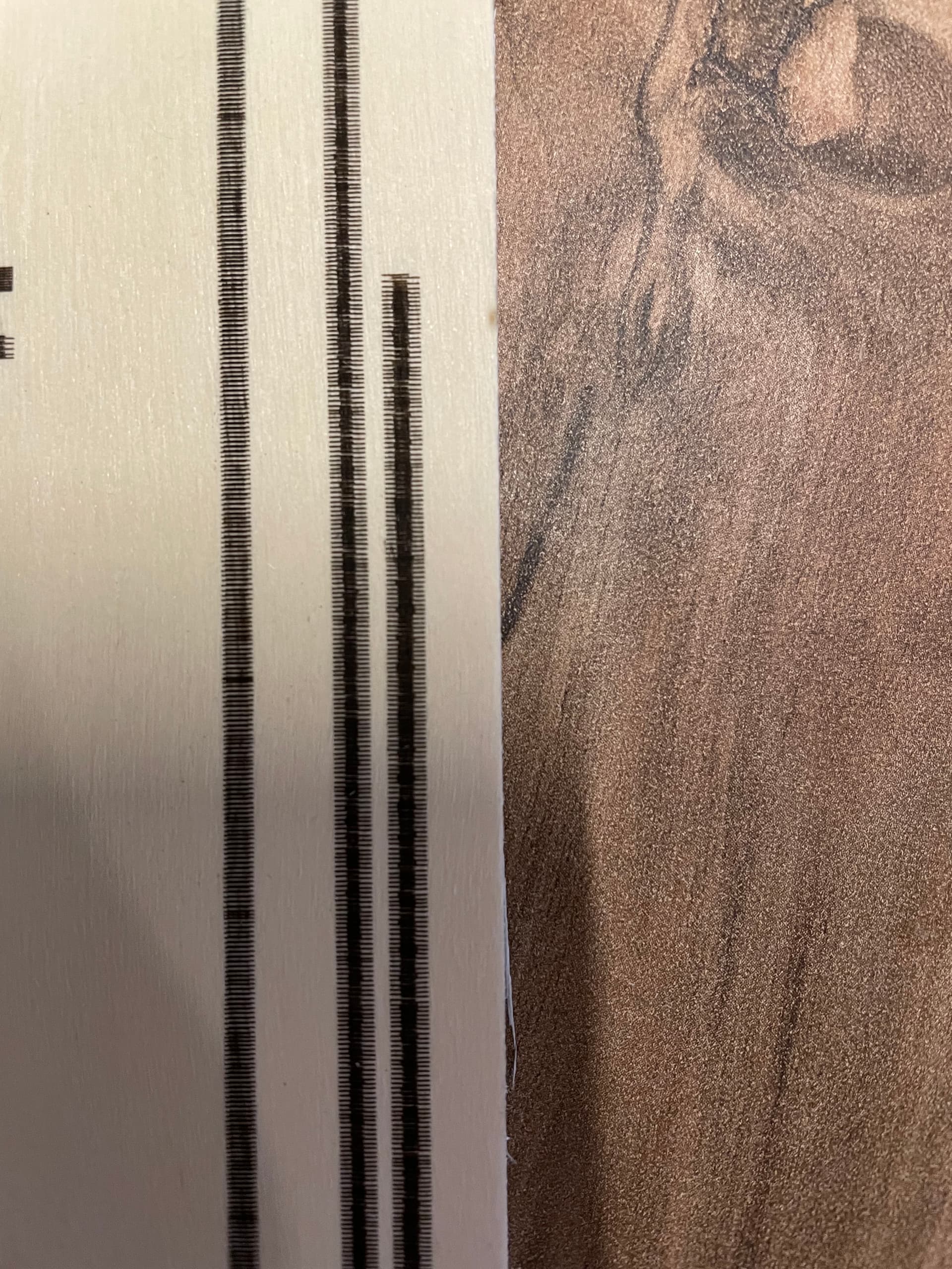
On the picture you can see my test photo (bi directional) and above there a 2 test bars. The left one is one directional and the right one is bi directional.
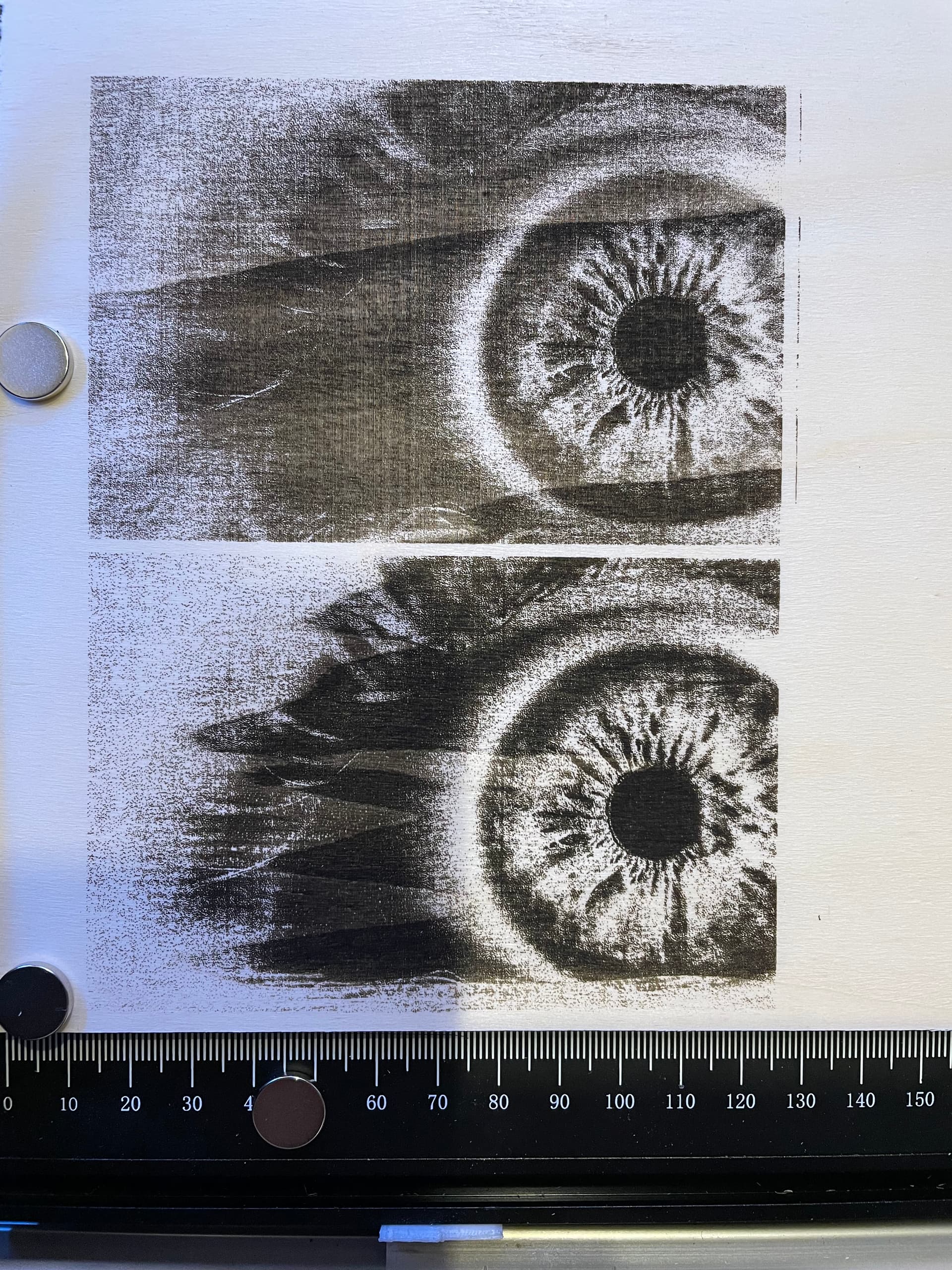
On this picture you can see the test photo engraved with one directional at the bottom and bi directional at the top (only adjusted the contrast but line interval is the same).
All example you can see on my pictures were engraved with the same speed and power settings. I didnt tweak at the settings at all. So i can definitely put this out as a source for the problem. The problem was there from one moment to another.
The two rectangle shapes from the right should have been engraved with an interval of .17mm instead
it gave me this strange looking rectangle. This test was done horizontal (y-axis). All the other stuff was scanned vertically.
Tomorrow i will try to check all the things you said.
EDIT
on my last picture the left rectangle was engraved bi directional also today. So bi directional scanning was really smooth when ive started my testings today, just a few lines overlapping over the whole bar, and suddenly after every turn there was this overlapping/touching of lines.
Bi-direction scan puts different stresses on the machine compared to uni-directional scan. It’s not unusual for this to cause different artifacts.
In the last drawing it looks like you might have an issue with offset scanning. First remedy is to make sure you’ve take any mechanical slop out of the system. Second remedy is to use offset scanning adjustment in Device Settings. LightBurn will accommodate for differences in direction once tuned.
By offset scanning you dont mean overscanning right?
I will try to detect mechanical issues tomorrow. I’ve already ordered some new belts because im not so happy with the actual condition of them. First it looked like they where a little bit loose so i tried to tighten them. I’ve payed attention that they are not too tight but one belt gives me a scratching sound while scanning now. They also look a little bit used. A week ago i adjusted the eccentric nuts on the y axis because i had shaky lines. When the direction changed while scanning the head began to shake.
Do you think it is possible that the stepper motors could have taken damage when they were stuck because the head was blocked by an object one time?
EDIT
on my last picture the left rectangle was engraved bi directional also today. So bi directional scanning was really smooth when ive started my testings today, just a few lines overlapping over the whole bar, and suddenly after every turn there was this overlapping/touching of lines.
It’s always possible but wouldn’t assume that’s the issue right now. You can run some test patterns to see where issues exist. If it narrows it down to a stepper issue then you’ll know.
It’s possible that you’re overtightened on belts on the Y-axis. It could be causing binding. And then a jump when it gets to the next step. Watching out for that. Could also be overtightening of wheels.
Nope, the problem wasn’t caused through activating bi directional scanning. It just were there from one moment to another. When i started my line interval test yesterday everything went fine. Just a few lines were engraved a litte bit to close every 50mm or so. But then suddenly every line was touching like you can see on the pictures.
So i’ve checked all the mechanical parts. I adjusted all belts and eccentric nuts. It’s all tight but not too much. The problem is still there. I tried to lower the speed from 3000mm/m to 1000mm/m and nothing changes.
I also noticed that the system seems to stuck if i put the speed to 6000.
But the confusing thing is, it only stucks when the laser fires.
Ive already contacted Atomstack support to ask what chipset (8 or 32 bit) is integrated and what the maximum speed limit is. Because in the controller settings it’s limited to 6000. Atomstack says there is a 8 bit controller and i can drive 9000 mm/m without loosing any steps. But that doesnt match with my experience and the limit in the controller settings…
What i havent said yet:
A week ago ive upgraded the system and mounted the Atomstack M50 module on the A5 system.
There were a new power supply for the new head that runs parallel to the normal power supply. Yesterday i noticed that i forgot to turn on the old power supply but the system was still running only with the new power supply. Only the fan of the laser was blowing slower.
Maybe the system took damage because there was not enough power at some time?
What do you mean by stick? What happens physically?
The part about it only happening when the laser fires is likely interesting.
I consider 6000 mm/min quite fast. As in I doubt you could ever achieve these speeds and certainly never use them, even it the MCU could support those speeds. I take any such marketing claims with a grain of salt.
The Atomstack A5 carries a stepper motor on the X-Axis gantry. Between that and the rest of the weight laser module it would be difficult to achieve those speeds. But maybe others with experience with that laser can speak up.
From this earlier Topic the A5 appears to be an Atmel based controller compatible with Arduino. So it’s definitely 8-bit.
What do you mean by parallel? Was one power supply connected to the controller and one to the laser module?
Where is the new power supply plugged in? What it the current rating for each power supply?
It’s certainly possible. The power supply and controller would be the vulnerable components, especially if the controller is not designed for that much current. I recall that the M50 by itself draws over 3A.
What is the timeline of the power supply incident and when you noticed problems?
If you have a meter, check that you’re getting a reliable 12 V from both power supplies.
I’m trying to think of where this leaves you. Maybe try switching the X and Y steppers. See if the problems follow the motor or follow the path.
Okay i did testing with 300mm/min and the problem is still there. I’ve done some more testing with different intervals and from interval of .5mm and higher the problem is slowly disappearing.
The systems slows down if i try to engrave a photo at a speed from 3500 or higher. When i set the speed to 6000 it starts driving at 6000 and everytime when the laser fires it slows down for miliseconds. But i think thats because of the 8 bit controller. I’ve red somewhere else that the controller can’t handle so many Gcode instructions. When i try to engrave a rectangle at 6000 everything is okay (less Gcode per second).
What do you mean by parallel? Was one power supply connected to the controller and one to the laser module?
Yes, the original supply is connected to the controller. The controller is connected to my laptop via usb.
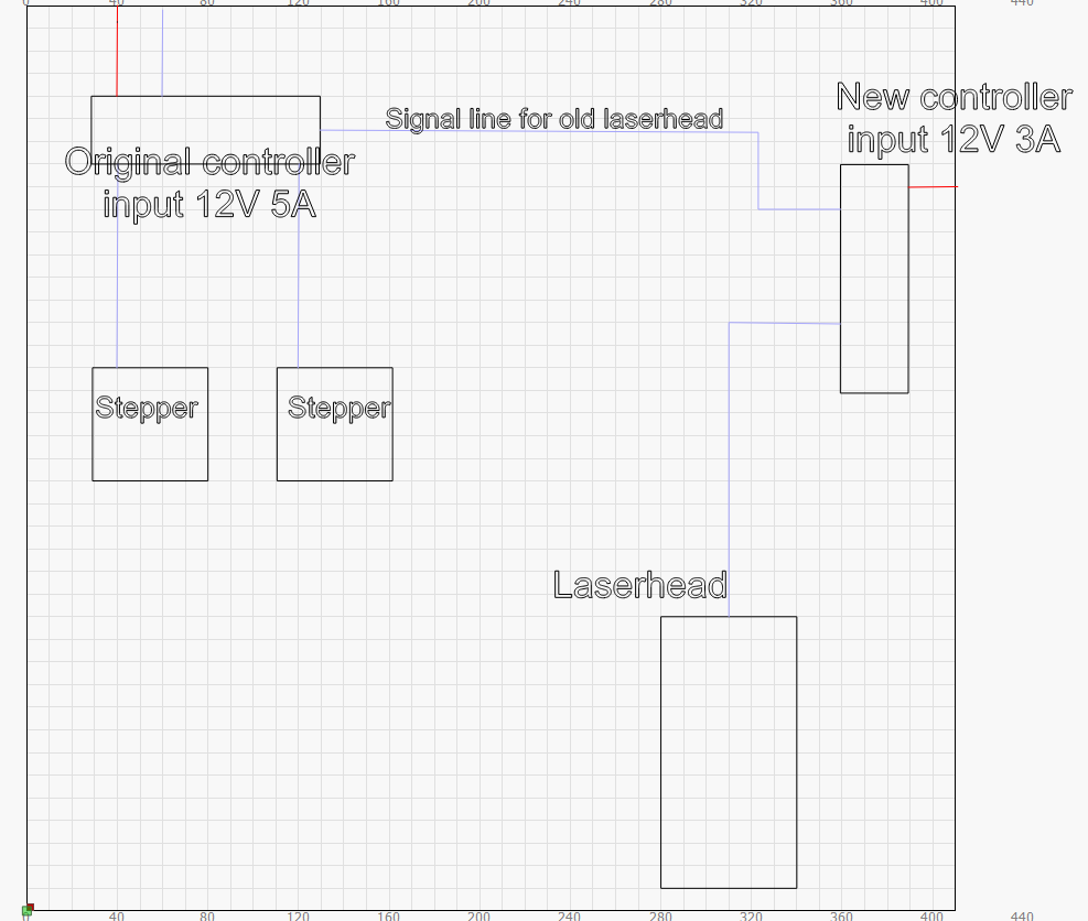
The signal line from the controller goes to the steppers and the pin that went to the old laser head is now going as an input to the new controller that came with the M50 module. The M50 controller has it’s own power supply (3 amps) I’ve tried to sketch it down (red lines come from the power supplys, blue input line at the original controller comes from laptop):
So at some time yesterday i’ve disconnected everthing and must have forgot to turn on the original power supply (5 amps). The system was running just through the new M50 power supply. Im not sure but from the timeline it could fit with the problem showing first time.
Meanwhile i am not sure if its really an mechanical issue because of problem is disappearing with a wider interval. Also im not sure if there is a use of switching the stepper since the problem is on both axis.
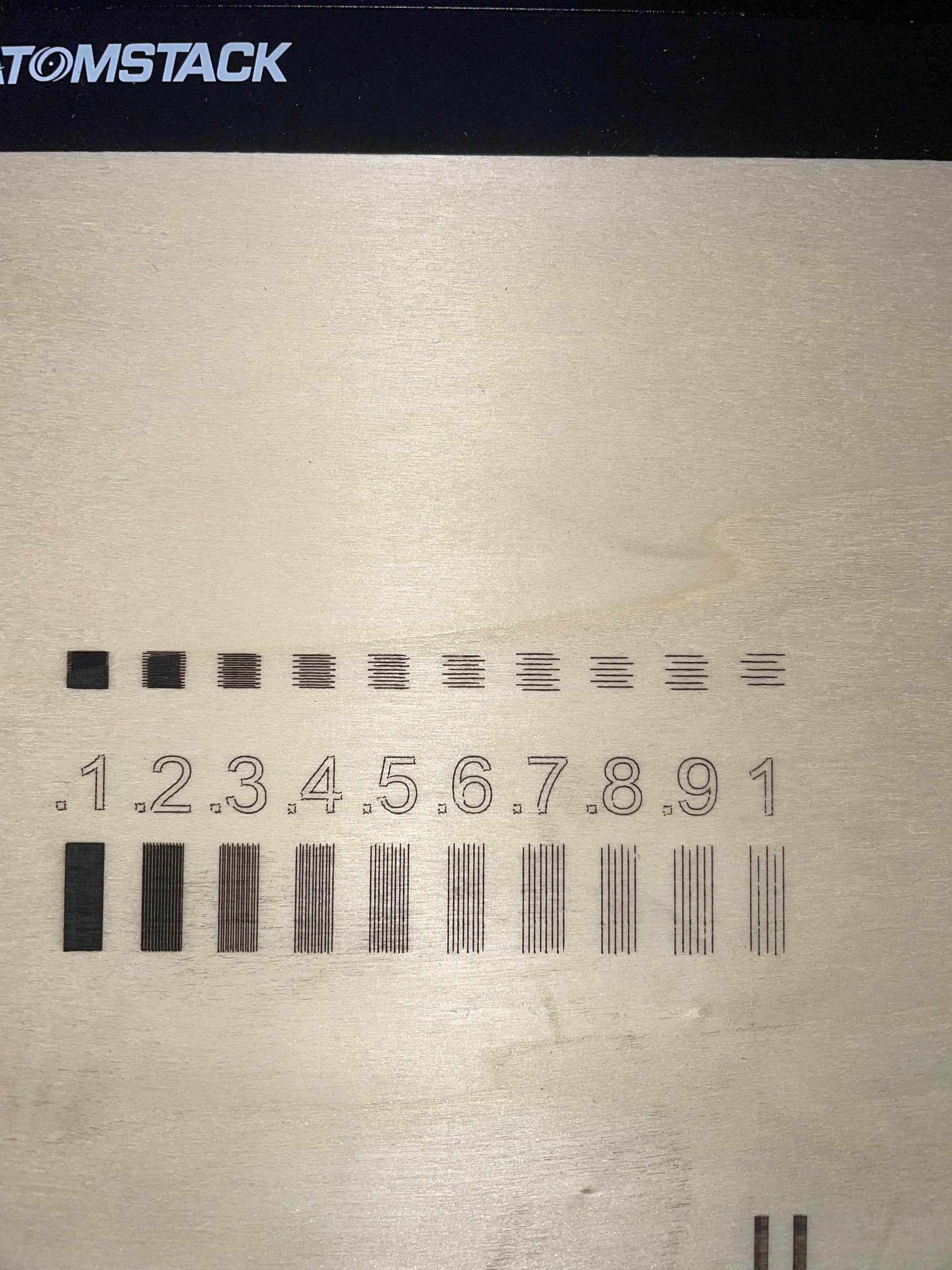
Based on the pictures you definitely have something going on. The numbers especially are telling to me. You’re not getting smooth consistent lines and some of the numbers are distorted. Also notice how the 4 sides of the periods are all curled? My first guess is that you’re overtensioned either on the belts or the wheels. It looks like binding to me. However, what’s strange is that there are gaps in the corners. Were those periods drawn as a single rectangle or 4 separate lines aligned to a rectangle?
But you’re saying you had none of these issues prior to the power supply issue? If so, that would point to the controller being bad. Laser module and steppers would probably have been fine.
The diagram is close to what I assumed that you had. One confusion though, you don’t have an actual controller connected to the M50 do you? I assume this is just an interface board for the M50.
If you want to run more tests you may want to try running a series of squares and circles at varying speeds. Also the vertical and horizontal line test at varying speeds. If artifacts are exaggerated with speed then likely not a controller issue.
Im fighting against these curly lines since i have this machine. So this is an older problem i had before the new interval problem. I have already tried to adjust belt and eccentric nuts very often in the last weeks. As i said im not satisfied with the condition of the belts. maybe they are stretched. i will replace them but i cant see a logic in saying its a mechanical thing since the interval offset problem disappears when interval gets bigger. that tells me that something else is going wrong. Maybe it’s the controller.
I dont think the module for the M50 is an actual controller. More like an interface module like you say. It’s getting the signals from the original controller and supplies the laser with power.
Will do more testing when ive replaced the belts.
If its not getting better then i might have to replace the controller if i get a new one. Already thinking about replacing the whole machine and just take the M50 module and mount it somewhere else
Im getting more confused and disappointed with every try. But luckily there are people like you that spend their time to help, so thank you for that!
If this has been an issue since the beginning then it has to almost certainly be mechanical. I’m very curious now. Your machine seems like it’s tracking straight on X and Y. So I’m guessing this is only happening when actively moving.
You see how the tails of those lines curl toward each pair? In in isolation I would think that the belts or wheels on the Y-axis are causing binding. This would also make me think that it could be related to the interval issue… perhaps there isn’t enough movement in the tight intervals to overcome the binding. But once you get to a certain interval size it snaps into position… like a detent. I’m speculating. What’s weird is the same feature is not seen on the left side… so not fully satisfied with that explanation.
Take a step back if you need. Try to remember that this is supposed to be fun. Some people play with their lasers with upgrades more than burning. Haha.
You’ve mentioned that bi directional scanning is a bit of a stressing factor for the machine. Could you explain this more precise? Because when i look more closely to the picture were i was engraving two test photos (eyes) i can see that the bi directional one is not as precise as the other one. You can see each line while the one directional photo looks smoother.
You have very little time between movements to restart the burn… so any movement during that time will show as a distortion
You have to be worried about scanning offset with bi-directional. You could have a significant amount of backlash in the system and if all you were ever was uni-directional engraving of photos you might never know. These type of things only show up if you are changing direction.
This is what I’m actually saying. Bi-directional will expose certain weaknesses/faults in the setup so the engraving will be worse. You need to be better tuned for bi-directional to work well.
I’ve done some more testing today. I was engraving rectangles (one directional) with different settings and the interval problem showed on the same x coordinates every time. I checked the belt again and adjusted it again and again and now the problem is gone (only for one directional scanning, bi directional scan is still unpossible). But when i try to move the x axis manually i can feel that it’s not going smooth and easy as it should. Also there is a little rubbing sound when x axis is movin. I’ll stick to my plan with changing all belts and try to accept the fact that bi directional scanning is not available for me. I’ve activated fast whitespace scan so that the distances where the laser doesnt fire will be driven more fast with 6000 since my absolut speed limit lays somewhere arround 2800 when the laser fires (8 bit controller )


 )
)