Hi berainlb,
I think that it doesn’t seem to matter if it’s turned on or off in my case. At the corners there is some sooth laying on the top of the material. Not the corners being burnt. So I think it has nothing to do with my problem as you said.
I will lookup the gcode and paste it when I am at the machine later. Hope you’ll get some usefull info out of it.
About the difference in the laser module - yes, sure it can be. I can’t find any data of the focal point size of the LU1-4 I had been using. Also for the LU2-10 I found 2 different infos - one saying 0,05x0,1 and the other one 0,07x0,06. Don’t know which is the right one. But is it possible that one of the first laser modules from Ortur would be preciser than the last one?
Nut just possible but likely. They way higher power is achieved is typically through larger diode arrays and higher operating current. And in the case of LU2-10 it’s even more complex as there are two separate diode packages that require optics to combine the light beam. These circumstances make achieving a consistent and fine dot size increasingly more difficult.
I don’t think I’ve seen any multi-diode offerings from any of the common vendors where the dot size was smaller than their previous single diode package offering. Of course the trade-off is generally worth it for the increased power and marketability of better cutting performance. I don’t think I’ve seen these marketed with a focus as having better engraving or detail than previous offerings. Only that they’re quite good at those things. Or better than some other alternative theoretical multi-diode laser.
Also keep in mind that there’s likely to be fairly considerable manufacturing variation. That’s at least what we’ve seen in previous single diode offerings. I would expect there to be even more with the higher complexity of multi-diode offerings. Dot size and shape is likely to have a bit of variation. I’ve never seen a manufacturer list their tolerances for this which I wish they would as people are often confused when their measured dot size doesn’t match the listed dot size. Or as you found, the multiple listed dot sizes.
Hey. Sorry, still didn’t make it to the machine to get you the gcode from the console. Will do that.
But something crossed my mind right now - I’m also having trouble with finger joints when cutting i.e. boxes. They’re (seems I’m the only one in the world with this type of issue) too tight. In principle everyone is having the opposite problem - joints beeing to loose.
I did a few test cuts - finger joints of 3mm x 6mm which I measured with my calliper - the readings were 3,1mm x 6,1mm. So, a negative kerf? ![]() Something everybody would love to have. Well. After struggling and reading some more articles I’m thinking again of my focus. It could be that I’m out of focus - to low on the material, so to say the focal point is beneath the material and I get a V shaped cut, where this lower part of the V (the focal spot) lays underneath the material. This could explain the finger joint nonsense and also maybe the burnmarks on top (the laser beam being too wide when hitting the material).
Something everybody would love to have. Well. After struggling and reading some more articles I’m thinking again of my focus. It could be that I’m out of focus - to low on the material, so to say the focal point is beneath the material and I get a V shaped cut, where this lower part of the V (the focal spot) lays underneath the material. This could explain the finger joint nonsense and also maybe the burnmarks on top (the laser beam being too wide when hitting the material).
Am I thinking the right way? I think I tried to adjust the focus some times after setting it with the gauge - but could be that I always lowered it a little bit. I don’t think I ever tried to lift it up… What do you think?
Well ok, then I have to live with that fact, that cutting such details I was used to is gone. So redo those of my projects with that tiny details to get them bigger or by just leaving them out. I could accept this for the way higher cutting speeds I am getting now with that module. But one area still needs attention regarding this spot size - image engraving where I need to get to the closest possible dimension of my laser dot so I can setup the LPI right…
While you may still have a focus issue concurrently I don’t think that explains the finger joint issue. Being out of focus would increase kerf, it wouldn’t allow for negative kerf.
Are you absolutely certain you don’t have a kerf adjustment configured on your layer? If that’s not it I would speculate that your axes need calibration.
You may want to run a simple calibration test. Draw the largest square you can reasonably burn on your laser. Then measure and compare actual vs design. Do they match?
I’d still encourage you to explore the focus as that’s how you’ll maximize cutting efficiency.
Yes, I’m sure that the kerf adjustment is set to off on all my layers. Did recheck that again - in fact I have never used it at all because I didn’t even know why to change that setting. Found it lately struggling on my issues after replacing the old module.
Axes calibration could also be a problem yes. I’ll have to find first the “biggest” square I can burn and then measure it. But how could that result in a negative kerf? The offset of my cutouts is the same on the Y and the X axis - both fingers are for about a 0,1mm wider on both sides - I cut out a rectangle with fingers on all the four sides of the rectangle (just FYI).
Oh. I think I misunderstood the circumstances then.
Can you upload the .lbrn file to review? I can’t imagine a scenario where this would happen under normal circumstances.
Ok, got al of the files now attached -
lb_test.lbrn2 (165.8 KB)
lb_test.txt (190.8 KB)
lbrn and gcode file
So all the fingers are 3mm x 6mm. When cut and measured they are 3,1mm x 6,1mm
Did you use a box generator or something similar for this?
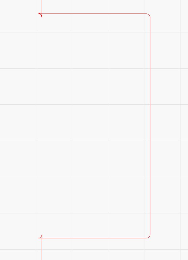
The lines generated have some characteristics of having kerf compensation hard-coded in:
Also, if you carefully measure the tabs, they are larger than the nominal 6x3 mm. If you stack the tabs into the slots, they aren’t the same size.
I think that accounts for the perception of negative kerf at least.
I don’t see anything obviously off in the gcode file that would affect power levels so likely not the root cause.
Hm, don’t realy know what now that meens what you pasted - why the lines are connected in that way. I downloaded this file from Etsy I think, in either case it’s not my work. So maybe I’ll do also the big square drawing you suggested, which I didn’t had time to do yet. Then I’ll also cut out a square and also compare LB with the actual cutout. But I also bought another design (some houses) from Etsy and there are also lot of finger joints - and had to scrape all the joints with a scalpel to get it together…
It appears the design you purchased has included kerk/corner clearance techniques designed right into the shapes - the little triangles at the corners are examples of this.
While it certainly works, it is less than desireable when you have the power to dynamically do the same from within LightBurn. It may take some time to edit them, but it should be possible.
No need at this point. I don’t think the fundamental issue is with calibration as I misunderstood the scenario.
Basically what’s happening is that the tab is bigger than 6x3 mm and the slot is smaller than 6x3 mm. So when you cut them out they’re not fitting properly.
The file that you purchased has included within the design itself the path the laser needs to take to account for kerf. It seems in this case that the assumed kerf is larger than your actual kerf so you’ve got that going for you.
You may want to ask the designer to provide a version of the file with a slightly smaller kerf size. If you give them your measurements they may be willing to adjust the file.
You could attempt this yourself but would be a bit of a pain to adjust them. You’d be better off recreating the tabs and slots entirely if you attempt that.
Well did some kerf tests now. A few finger joints playing with the kerf offset and finished at about 0,0100 mm. So might be the files which are causing problems.
Also cut a 50mm x 50mm square and measured it 50,1mm x 50,1mm. I think that’s totaly ok. Right?
Moght be jist to get used to all new details using the new module. But still have to figure out how to get rid of the top burnmarks on my cuts and engraving…
Are you saying with kerf adjustment enabled or without? If without then perhaps you do have a calibration issue as the measured amount should never be bigger than the nominal dimensions. Not sure what kind of material you’re cutting but I’d expect at least a 0.1 mm kerf. As a note, kerf adjustment should be set to half the measured kerf amount if you want to use that.
I’m reviewing some of the original photos on this thread. Are you referring to the smoke residue at what looks like the initial piercing point of the laser? If so, that could be something inherent to the material. Some materials are more likely to generate a residue like that than others. You could remedy with stronger air assist or by pretreating the wood in some way. Either masking it off or some sort of protective layer. You may be able to brush or blow it away.
There could still be a setup issue causing it. For example, if your laser is not quite square to the material that could increase the chance of this. You could try decreasing power and cutting through in multiple passes.
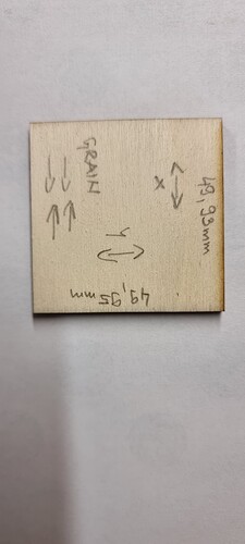
Well, did tighten all the screws and belts again, checked it’s all squared up. And cut another 50x50 square. Now measuring it with the digital calliper it states 49,93mm on the X axis and 49,95 on the Y axis. Thats ok now, right?
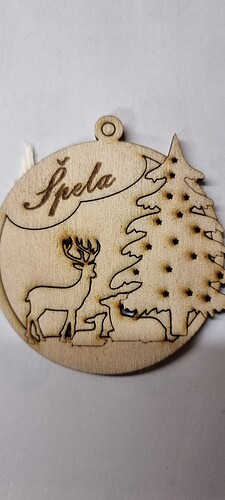
Regarding the marks on top - I attached another photo of a cutout. There are visible shades of burns or sooth as you said. These can’t be just brushed or wiped away - have to sand everything down. I changed my cut settings for these one to 430mm/min with 90% and 2 passes. And it’s not a noticable change regarding the sooth. My air assist is run with a Resun ACO12 (150L/H) which I have been using also with the orevious laser module with no such issues.
Was this with kerf adjustment enabled or no? If no, that’s a surprisingly small kerf or your machine is cutting very slightly big. If you really want it to be dimensionally accurate try engraving a very light line for a large square on some paper or cardboard. Measure the size of the engraved line. That should remove kerf from the equation and tell you if machine axes are calibrated correctly.
If this is with kerf adjustment the numbers seem quite reasonable. Up to you if that’s accurate enough. You could likely get even closer if you care to try.
So the old laser using the same air assist you had no issue with soot? 150L/H (2.5L/m) is fairly low, really the base level for air assist. Going dramatically higher could likely increase cutting power and reduce discoloration.
You changed to this from what previously? Are you using the least power necessary to make it through? If not, try reducing power until you’re just barely cutting through.
What settings did you use on the previous laser?
Ok. I’ll try the square method and measure all up. I’m getting now really close with the kerf. I’m now cutting things, where the kerf isn’t important at all. When I’m done with that job I’ll get into the kerf and joints part.
Regarding the air assist, I mistakenly tiped /H instead of /min
And for the cut settings - 430mm/min 90% and 2 passes is getting thru so it falls out. I’m trying to set the cuts like that (without having to pop things out) because I’m cutting lots of details and they brake when the cut isn’t all the way thru.
The settings for the old modules were 220mm/min with 95% and 3 passes ![]()
Okay. Took a look and it seems a fairly standard aquarium pump situation. Those are relatively low pressure low volume as compared to an air compressor situation. Going to a decidedly higher pressure would yield a benefit in cutting for sure if that’s valuable to you.
If it’s the minimum for this to occur then that’s the best case. You may want to try different speeds and power to see if that changes the amount of soot generated. If you go to 3 passes at 220mm/min with much lower power are you able to duplicate the outcome of the old laser?
Yeah, I also have a bigger shop air compressor, which could blow much more air out. But it’s loud as hell - can’t work with that. I got it now to cut smooth, fast enough for now, with very small amount of sooth to sand away.
If I go now to 220mm/min and 3 passes I’m not getting anywhere as this are the settings for the old module.
Is your bed level?. I have this issue every now and then and I have to level my bed ever so often…not a lot, but enough to get right of the burns.
If your bed isn’t level the beam will go in and out of focus giving you burn marks.


