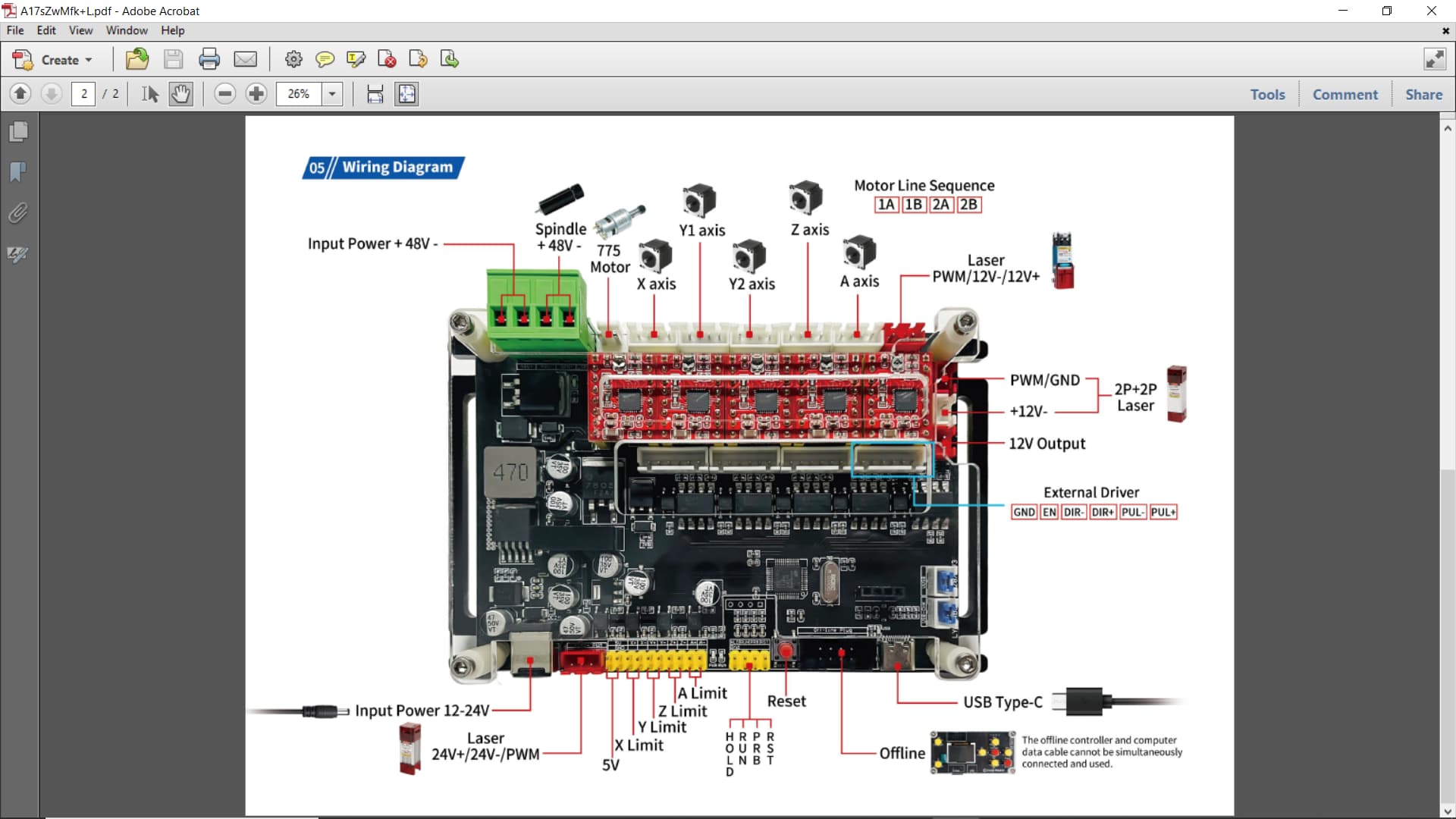
Running a generic GRBL card, and I want to use the M8 command with a relay for my air pump. None of the outputs on the card are marked M8. I have done some online research and see that there is theoretically a way to map the outputs in GRBL. But the docs I have found have a higher expectation of ability than I currently posses.
Anyone suggest a source for more complete GRBL explainations?
If that’s the case then this might be impractical for you to tackle as it involves some understanding of electronics. May be easier to swap a controller with air assist pins exposed.
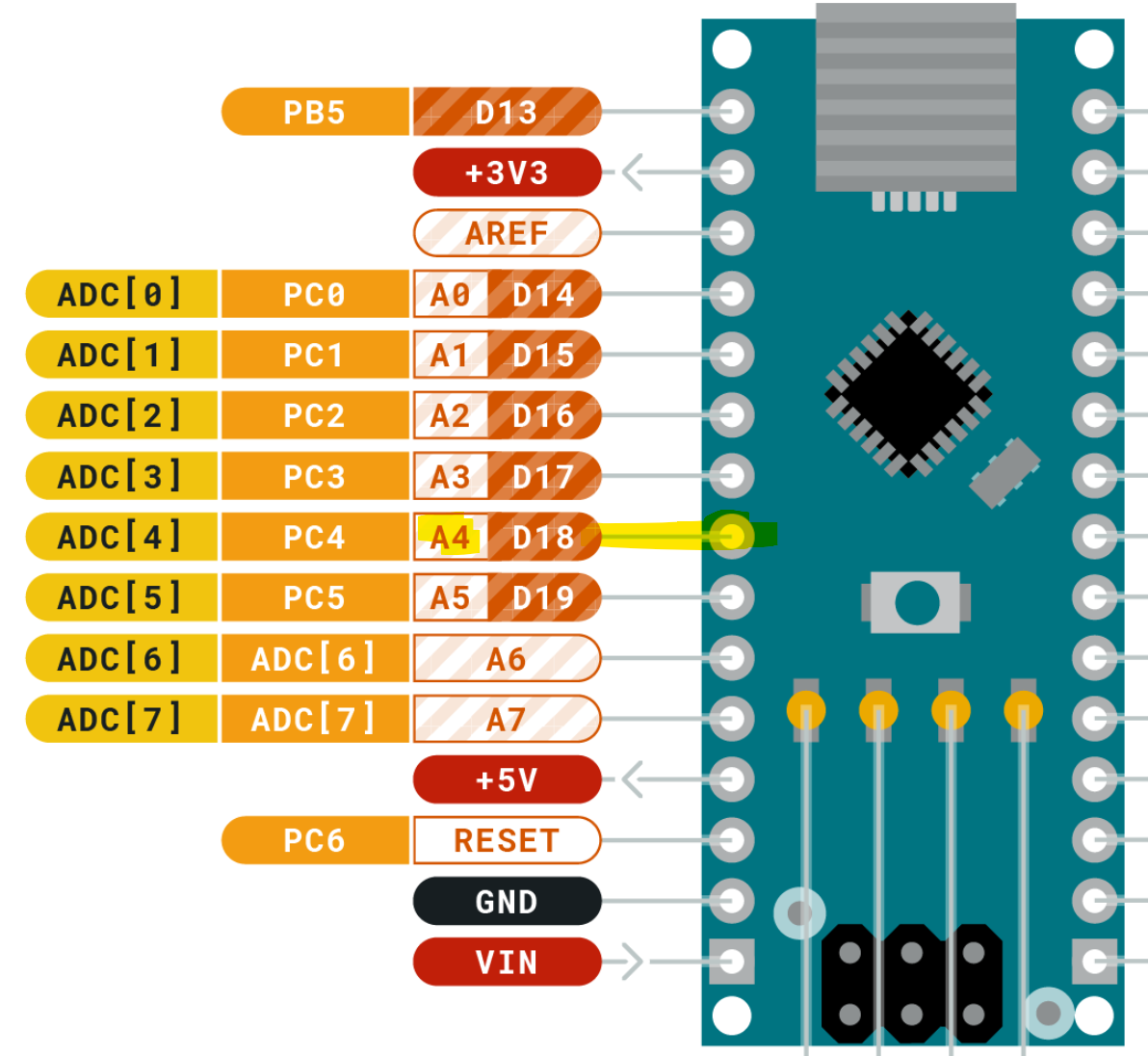
Essentially the information in the previous link explains what pin from the arduino is used to send the signal. In this case analog pin 4. In spite of the name this will be digital output signal, so 5V represents on, 0V represents off. You could not directly turn on a pump or solenoid with this so you’d have to bring in other components to make this work.
If your controller does not expose all the arduino pins you may be able to tap directly into the atmega chip pin that’s tied to analog pin 4 which I don’t know off hand.
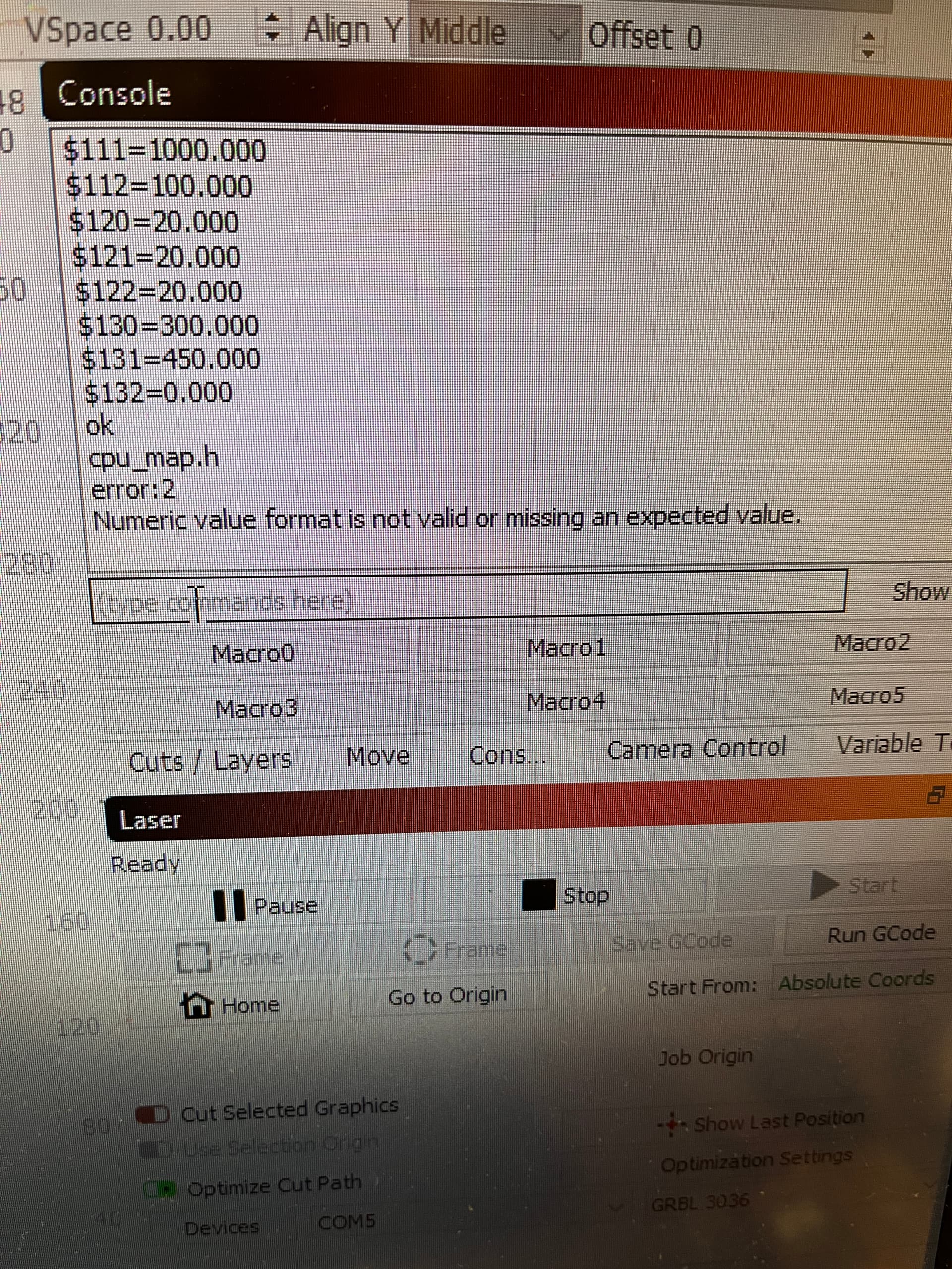
Programming is my problem, the wiki assumes everyone has the knowledge of what to do with these type instructions, I don’t understand how this is done, one line at a time, all lines together? How is it compiled, debugged, saved?
I understand that I would have to put a relay on the output, I’ve worked in robotics for 25 years, but the lightburn air feature uses M7 or M8, and I don’t see that here.
/* The cpu_map.h files serve as a central pin mapping selection file for different
processor types or alternative pin layouts. This version of Grbl officially supports
only the Arduino Mega328p. */
#ifndef cpu_map_h #define cpu_map_h
#ifdef CPU_MAP_ATMEGA328P // (Arduino Uno) Officially supported by Grbl.
// Define serial port pins and interrupt vectors. #define SERIAL_RX USART_RX_vect #define SERIAL_UDRE USART_UDRE_vect
// Define step pulse output pins. NOTE: All step bit pins must be on the same port. #define STEP_DDR DDRD #define STEP_PORT PORTD #define X_STEP_BIT 2 // Uno Digital Pin 2 #define Y_STEP_BIT 3 // Uno Digital Pin 3 #define Z_STEP_BIT 4 // Uno Digital Pin 4 #define STEP_MASK ((1<<X_STEP_BIT)|(1<<Y_STEP_BIT)|(1<<Z_STEP_BIT)) // All step bits
I originally thought that you had determined that your board was not exposing the air assist pin but I understand now that you’re saying that nothing on the board indicates M8 specifically.
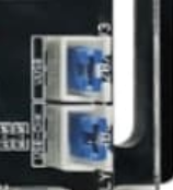
It’s entirely possible that the board doesn’t expose the pin. If anywhere it would be near the yellow headers marked with RST, PRB, RUN, HOLD.
Else if you were inclined you could tap directly onto the atmega.
If you did not need one of the existing pins, you could customize GRBL to reuse that pin for air assist. That would be far better than tapping onto the MCU pins.
identifying the type of board that you have. If you look at the cpu_map.h there are lines that start with “#ifdef”. These are pre-processor directives that dynamically change what code will be processed or not. Note that there are different pin mappings depending on hardware type. I’m not familiar which your particular board falls under. If we assume that it falls under the general first group with the line #if !defined(ENABLE_DUAL_AXIS) then indeed we see coolant flood (M8) tied to analog pin 3.
#define COOLANT_FLOOD_BIT 3 // Uno Analog Pin 3
The second aspect is reassigning the pins. So let’s say you wanted to switch with the Probe pin: