Perhaps a side cutter could shorten the work or get you close enough of a fit.
I’ve got one of these controllers on Order and I think @jkwilborn has one.
I’d like to confirm that yours arrived optioned for the Variable Spindle OPT V in the Build Options. The Variable Spindle code is used to control the laser.
From LightBurn, While connected to your laser, please request a system information report from the controller. In the Console window, type the following:
$i
then press enter.
Please copy the response from the Console window into a reply here.
This report ‘should’ offer the build options and the build date.
It looks like most of you already have wiring manual:
I think you’re right, TTL signal ground and (+12/+24) power return grounds are probably connected on the MKS DLC32 board.
TTL Stands for Transistor-Transistor Logic - it’s signal only. You won’t get 5W into the laser let alone 60 on the signal pin.
If your laser module requires a TTL control input, it’s going to need +12, TTL, and ground. (page 9)
If it’s a 12V pulse it’s 12V (modulated) and ground. (page 10)
All of my led modules I own of are tolerant to 12V input on the pwm, as it goes to an optical isolator… Don’t confuse this with 12V being on, it still is a ttl range, so anything over a TTL high voltage will read high. It’s just tolerant of 12V.
This is from the wiki of my NEJE 40630 laser module. I’d check my module to be sure. There should be no 12V on from this board driving the ttl inputs of the laser module. They specify it’s 0 to 5V tll.
Input: 12V 3A +
Optical Power: 5W +
Wavelength: 450nm
Laser Class: Class 4
Number of Diodes: 1
Light Source: 1 X LD + C-Lens
Focus Spot:
PWM Input: VPP(3.3-12V), Recomend 1KHz,
@Sohmnibus can you find us a link to the board you have if it isn’t like my photo in post 2.
JohnJohn - I will try to do that tonight or tomorrow. Lasering is a hobby and life takes up the other 99% of the hours in my day. Well, that and sleep. But less so on the sleep the older I get… Does it matter that I don’t have the laser connected when I run that command? The steppers are connected, but because of the pin harness issue I haven’t attached the laser yet. Though I did manage to find the right 3-pin harness while in town this evening, so if I need to I can try to rewire to the correct harness.
JKWilborn - I have attached a photo I took of the board. Yes, it’s a crappy photo. Sorry about that. Like I mentioned, I have a shake I can’t much control most days.
The laser module itself is annoyingly lacking in information, but I DO know that the INPUT, OPTICAL POWER, WAVELENGTH, LASER CLASS, and NUMBER OF DIODES are exactly the same as yours. When I search the stamp across the diodes control board - LY-BC-0160 V2.1 - it looks like it’s Pro Photonix laser. Other than that I can’t tell you much.
One more question: The original board and the DLC32 both have a Y1 and Y2 connection. The Y-axis was connected to Y2 on the original board, so I’m assuming that’s the same on the DLC32? I thought I read somewhere that the Y1 was specifically to control a CNC, but I don’t guess I understand why a Y-axis would differ on a CNC as opposed to a laser since both move back and forth across the same axis. Anyway, if you know I’d like to be wiser as to why choose one over the other.
And thanks, everyone! I love me some learnin’, but this is a subject that doesn’t really have a noob to advanced curve. Everything I find seems to start in the middle of a subject and just expects everyone will know everything that’s unstated to that point, apparently. I call it the “If you don’t know the secret handshake you can’t be in the club” phenomenon. It’s like trying to get a full answer out of a doctor. So, all you input is incredibly appreciated. Thanks again!
I don’t know about your original board but it looks like the DLC32 has Y1 and Y2 but both are driven by the same stepper driver so I assume it’s just a duplicated signal or possibly a mirrored signal. It shouldn’t matter which you plug into. You could potentially use both if you had a 2-stepper Y-axis machine.
Maybe I’m wrong about the Pro Photonix, or maybe they only supply the lens. The teeny tiny markings on the housing are K40B50W-CL. I can’t find the CL specifically, but the “T” model is a 5.5-watt, and the “i” model is a 15-watt. Looks a lot like the laser used in the Neje machines.
Connecting the control board to the Computer and connecting in LightBurn will allow us access to the Build Info report. Some USB cables supply power and in those cases the reports are available without even connecting the motor / laser power supply.
This is all that came up:
"$i
[VER:1.1.2022051001:]
[OPT:PHSW]
[MSG:Using machine:MKS DLC32]
[MSG:Mode=AP:SSDI=MKS_DLC:IP=XXX.XXX.XXX.XXX:MAC=XX-XX-XX-XX-XX-XX]
ok"
Also, this is the one I purchased, with the TS35 touchscreen:
So, nobody responded. No biggie. Problem resolved.
I managed to remove the wiring from the 2-pin TTL harness, then rewire the single wire into the Signal line of a 3-pin harness (after several attempts and using the wrong tools for the job), got it plugged in, and it all worked. The board had been given an old firmware for CNC and the axis buttons all worked in reverse, but after updating the firmware to the most current Laser firmware (I actually had to update twice, to the 3rd update, and then the most recent because it wouldn’t take the most recent firmware otherwise for some reason) everything runs perfectly.
And now you know that some wiring changes may be necessary, but the Makerbase DLC32 v2.1 works just as good or better than the original board.
Thanks for the advice and information!
Didn’t realize you were waiting on a response. Glad you’re up and running.
Looks like you ran into a firmware issue. Not sure if you got to that point but looks like you would have needed to anyway given that your previous firmware wasn’t equipped with variable power based on what’s shown here:
Normally you’d have a V
showing here indicating variable spindle/power.
I got it all functioning properly. I just could straight upgrade to the latest firmware - I had to jump back to the 3rd release before I could then follow that upgrade to the latest release. Other than that it worked fine.
I actually really like this new board. I can increase or decrease speed or power at the machine while in the middle of a job without having to stop and start over again as I did with the previous controller; zeroing my axis’s is simpler; and I have the choice of a private or open remote session; IE, I connect to the machines private network to do remote work (but that disconnects me from my own network and internet), or I can connect to the IP of my machine on the primary network. It’s the same way my DSLR camera works for retrieving or operating the camera. Plus it’s slightly faster than my previous board, which shaves a couple minutes off long jobs. I’m glad I upgraded, and won’t hesitate to do so again in the future should I need to.
Anyway, I’m up and running and enjoying my laser again! And off I go to do it some more. Cheers!
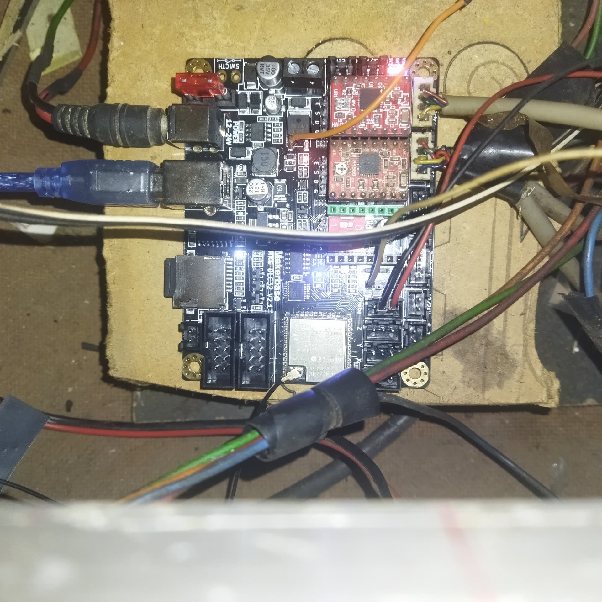
so if you want to connect you makerbase DLC32 v2.1 to your laser power supply . you solder the ttl(N on laser power supply) to the left leg of the laser connecter mosfet make sure u use the left leg . then take the L connector and connect it to the SCL pin (for I2C) then you are done no need for external control using variable resistor .
have attached my connections picture. now can use lightburn to control your laser power
in short
ttl output of the DLC32 → IN of the lps?
Along with SCL → L of the lps?
Is this ttl output of the DLC32 → IN of the lps?
Along with SCL → L of the lps?
I didn’t know it was configurable like this…
The standard way to connect these in a K40.
I’m not a fan of the potentiometer game, so this is nice to know… Is there any other configuration required?
Thanks…
no other configuration and yes ttl is your N and SCL in your L of UPS
That’s great… I poured over the documentation but couldn’t find anything like this…
Where did you locate it?
What firmware are you using…?
im using grbl 1.1f and this can be applied to all other boards like the skr 1.3 ,makerbase sgen_L etc just connect the left leg of the mosfet to get ttl then you make changes in smooothieware to correspond with your connection the on off (L) part is easy as you can simply use any freepin on those bigger boards
What do you mean?
There is source code to change?
I have one of these boards, I’d like to wire it up to the OMTech and see how it works…
Seems that it’s more complicated than you first stated…
Thanks
Is the left pin of the mosfet the gate? If so, it’s inverted from the output… and feed to IN? This does make sense since the spindle is pulled to ground allowing supply voltage flow through the spindle.
Would you have the modified source to re compile this available?