New here - Not sure this is the right Community for this question, so if not, please let me know so I might redirect.
So, this is a question about wiring to a Makerbase DLC32 v2.1, specifically for the laser module itself.
The mainboard on my laser died. After researching it looked like the DLC32 was my best choice for a replacement. However, I’m a tad confused now that I’m connecting wires.
On the original board there are 3-wires in a 3-pin harness coming out of the laser and back to the control board, but at the original board end it’s broken into a 2-wire harness for the 12V connection, and a single wire into a 2-wire harness for a 2-wire TTL connector. If I understand this correctly they simply ran 12V Hot and Ground to the 12V connector on the original board and the laser power to one pin of the 2-pin TTL connection on that board.
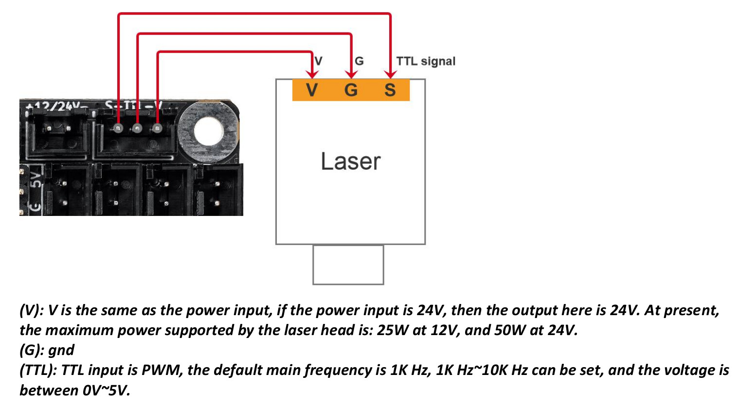
Since the MKS DLC32 board has a 2-pin 12V connection and a 3-pin TTL connection, I can’t use my single-wire 2-pin harness in the 3-pin connection as I see it, so to remedy this I would need a 3-pin harness for the TTL connection. Does this alleviate the need for the 12v connection? Looking at the DLC32 schematics it looks like 12V Hot, Ground, and the Laser would all run from the TTL connection, but I want to be sure before I move forward. If this is the case, can anyone recommend an already pinned cable? I would need around a 4.6-foot / 1.4m cable. I don’t want to try and wire harnesses, purely because a bit of bad wiring in the past left me a bit squeamish to try it again and fry a perfectly serviceable board or, worse yet, laser.
I have the same data sheet with schematics, and yes, this is my NEW DLC32 v2.1 configuration. But that’s not how my original board is. It has two 2-pin connectors, one a 12V and the other the TTL. The cabling from the laser is 3-pin at the laser, but it then splits out to two 2-pin harnesses at the board end. One of those 2-pin harnesses houses V and G and goes into the 12V connection on the original board, and the other 2-pin harness has the 3rd cable going into only the S pin (leaving the other pin-slot empty) and plugs into the TTL connection. 3 cables across two 2-pin harnesses, as the original board is configured. But to get that same cabling to work on the DLC32 board, I’d have to cut the wires at the board end and solder them into a 3-pin harness for the TTL connection, because I can fit the 12V 2-pin harness into the 12V connection, but I can’t plug the other 2-pin harness into the 3-pin TTL connector on the DLC32.
Is it correct that the 'V’oltage connector in the TTL connection is 12 OR 24V, or is it ONLY 24V? The wordage is kind of vague, since it only examples 24V, though my logical mind says either/or 12 OR 24V.
Use a meter to confirm but I believe your board will output 12V or 24V based on input voltage. So if you use a 12V supply the board will output 12V. If you use a 24V supply it will output 24V.
I may be wrong about this so please confirm.
As far as the wiring, as long as you can get the 3 wires going to their respective positions you should be fine. I assume one set of wires is redundant, likely the ground wire.
For ease, instead of using the full 3-pin port on the board you could use only the S and G pins of that port, and then use the 12/24 V port for the other connector. You would put the V labeled pin from the laser module to the + labeled pin on the 12/24 port.
The power supply is 12 volts. The Laser is a 60-watt 5-watt output.
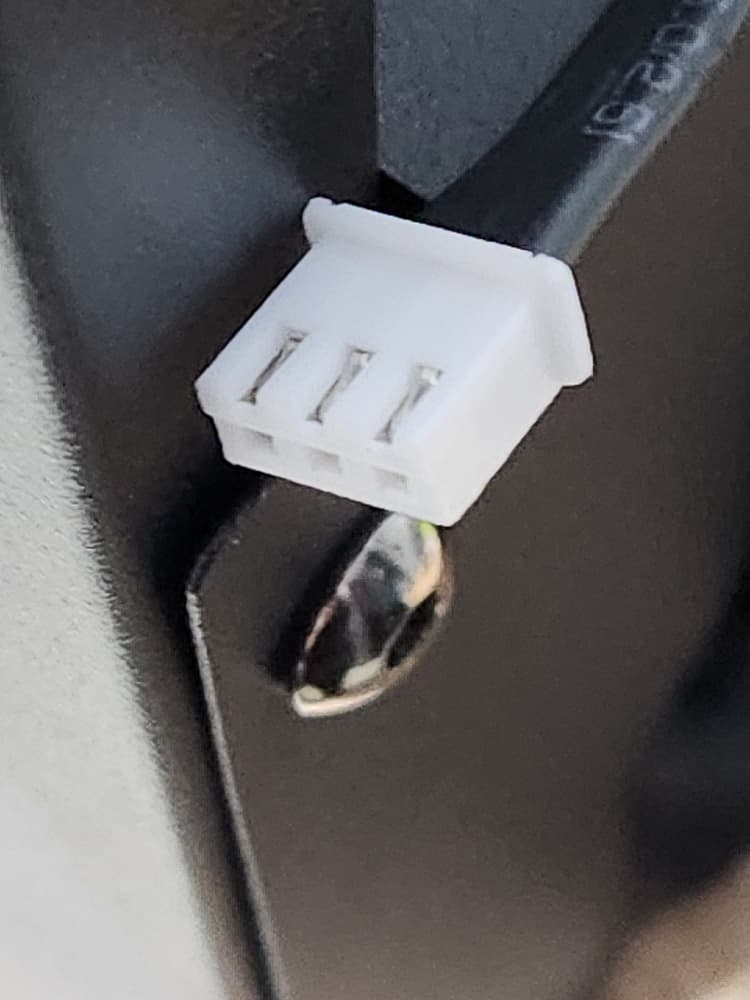
I’m not sure I’m explaining this well, so here are some pics. The first one shows the 3-pin harness that connects to the laser module itself. The 2nd is one of the two 2-pin modules at the other end of the 3-wires, this one showing the single 'S’ignal wire going into the harness, that would then fit into the TTL connection on the original board, while the other 2-pin harness has the other 2 of the 3 wires going into the 'V’oltage and 'G’round connections of the 12V connector from the pic in my last reply. So, I’m assuming I’m going to have to turn the two 2-pin harnesses into one 3-pin harness? Unless there’s another option?
And yes, the DLC32 will do either 12 or 24 volt, but the wordage is confusing where the TTL connections are concerned. But I believe the V pin will do either or.
Ah, I see what you’re saying. Yeah, I’d rather just go 3-pin to 3-pin, laser straight to TTL and call it good and not have to try and wire the harnesses myself. I used to feel pretty confident about such things until I toasted a control board the last time I tried it and it cost me more than it should have.
My next question, then: What do they call those harnesses? I thought they were called “Flat” or “Molex” or sometimes “Electrical”, but I can’t seem to find any listing of 3-pin-to-3-pin harnesses of that style when I try to Google them.
I CAN reuse the cable, but I was trying to NOT pin the cable myself to a new harness to go from two 2-pin harnesses running the 3 cables from the laser to one 3-pin harness. But I can only find harnesses, not pre-harnassed 4.5-feet cables, so I guess I’m going to have to.
No. I’m saying is there a reason you’re set on going with a 3-wire solution? You could reuse your existing cable without modification from 3-pin on laser module to the two separate 2-pin ports on the board. Unless I’m missing something you could do this without modifying anything unless perhaps the pins are reversed… which is easy to remedy by popping out the leads.
My original and now dead board had two 2-pin male connections on it, one labeled 12V, which the V and G cables from the laser went to in the 2-pin female harness, and the TTL labeled connection, which only the S cable went to in its 2-pin female harness.
The new DLC32 board has one 12V 2-pin connection, and one 3-pin TTL connection. The one 2-pin harness with V and G will fit in the 12V connection on the new board exactly as meant to, but the cable running Signal and ending in the 2-pin harness won’t fit in the 3-pin connector on the new board because the hold-clips are in the wrong place. Though I suppose I could Dremel them off to get it to fit. But otherwise, the 2-pin female and the 3-pin male are incompatible as far as fit. Unless you see something that’s entirely flying over my head. But as far as I see it, I have two 2-pin female harnesses running 3 wires from the laser, and one of those won’t fit the new board the way its needed.
Yeah. If the hold-clips were on the outside edges, that’d be fine. But being as they are along one of the long sides, it prevents me from inserting it in the connector. And they are the half-arrow type instead of the pull out type, which means I can’t just pull them off since they are part of the housing. But my Dremel idea just might work if I can keep my old hands from their usual tremble…
I’ve got one of these controllers on Order and I think @jkwilborn has one.
I’d like to confirm that yours arrived optioned for the Variable Spindle OPT V in the Build Options. The Variable Spindle code is used to control the laser.
From LightBurn, While connected to your laser, please request a system information report from the controller. In the Console window, type the following:
$i
then press enter.
Please copy the response from the Console window into a reply here.
This report ‘should’ offer the build options and the build date.
It looks like most of you already have wiring manual:
I think you’re right, TTL signal ground and (+12/+24) power return grounds are probably connected on the MKS DLC32 board.
TTL Stands for Transistor-Transistor Logic - it’s signal only. You won’t get 5W into the laser let alone 60 on the signal pin.
If your laser module requires a TTL control input, it’s going to need +12, TTL, and ground. (page 9)
If it’s a 12V pulse it’s 12V (modulated) and ground. (page 10)
All of my led modules I own of are tolerant to 12V input on the pwm, as it goes to an optical isolator… Don’t confuse this with 12V being on, it still is a ttl range, so anything over a TTL high voltage will read high. It’s just tolerant of 12V.
This is from the wiki of my NEJE 40630 laser module. I’d check my module to be sure. There should be no 12V on from this board driving the ttl inputs of the laser module. They specify it’s 0 to 5V tll.
Input: 12V 3A +
Optical Power: 5W +
Wavelength: 450nm
Laser Class: Class 4
Number of Diodes: 1
Light Source: 1 X LD + C-Lens
Focus Spot:
PWM Input: VPP(3.3-12V), Recomend 1KHz,
@Sohmnibus can you find us a link to the board you have if it isn’t like my photo in post 2.
JohnJohn - I will try to do that tonight or tomorrow. Lasering is a hobby and life takes up the other 99% of the hours in my day. Well, that and sleep. But less so on the sleep the older I get… Does it matter that I don’t have the laser connected when I run that command? The steppers are connected, but because of the pin harness issue I haven’t attached the laser yet. Though I did manage to find the right 3-pin harness while in town this evening, so if I need to I can try to rewire to the correct harness.
JKWilborn - I have attached a photo I took of the board. Yes, it’s a crappy photo. Sorry about that. Like I mentioned, I have a shake I can’t much control most days.
The laser module itself is annoyingly lacking in information, but I DO know that the INPUT, OPTICAL POWER, WAVELENGTH, LASER CLASS, and NUMBER OF DIODES are exactly the same as yours. When I search the stamp across the diodes control board - LY-BC-0160 V2.1 - it looks like it’s Pro Photonix laser. Other than that I can’t tell you much.
One more question: The original board and the DLC32 both have a Y1 and Y2 connection. The Y-axis was connected to Y2 on the original board, so I’m assuming that’s the same on the DLC32? I thought I read somewhere that the Y1 was specifically to control a CNC, but I don’t guess I understand why a Y-axis would differ on a CNC as opposed to a laser since both move back and forth across the same axis. Anyway, if you know I’d like to be wiser as to why choose one over the other.
And thanks, everyone! I love me some learnin’, but this is a subject that doesn’t really have a noob to advanced curve. Everything I find seems to start in the middle of a subject and just expects everyone will know everything that’s unstated to that point, apparently. I call it the “If you don’t know the secret handshake you can’t be in the club” phenomenon. It’s like trying to get a full answer out of a doctor. So, all you input is incredibly appreciated. Thanks again!
I don’t know about your original board but it looks like the DLC32 has Y1 and Y2 but both are driven by the same stepper driver so I assume it’s just a duplicated signal or possibly a mirrored signal. It shouldn’t matter which you plug into. You could potentially use both if you had a 2-stepper Y-axis machine.
Maybe I’m wrong about the Pro Photonix, or maybe they only supply the lens. The teeny tiny markings on the housing are K40B50W-CL. I can’t find the CL specifically, but the “T” model is a 5.5-watt, and the “i” model is a 15-watt. Looks a lot like the laser used in the Neje machines.