Connecting the control board to the Computer and connecting in LightBurn will allow us access to the Build Info report. Some USB cables supply power and in those cases the reports are available without even connecting the motor / laser power supply.
This is all that came up:
"$i
[VER:1.1.2022051001:]
[OPT:PHSW]
[MSG:Using machine:MKS DLC32]
[MSG:Mode=AP:SSDI=MKS_DLC:IP=XXX.XXX.XXX.XXX:MAC=XX-XX-XX-XX-XX-XX]
ok"
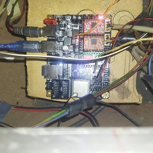
Also, this is the one I purchased, with the TS35 touchscreen:
So, nobody responded. No biggie. Problem resolved.
I managed to remove the wiring from the 2-pin TTL harness, then rewire the single wire into the Signal line of a 3-pin harness (after several attempts and using the wrong tools for the job), got it plugged in, and it all worked. The board had been given an old firmware for CNC and the axis buttons all worked in reverse, but after updating the firmware to the most current Laser firmware (I actually had to update twice, to the 3rd update, and then the most recent because it wouldn’t take the most recent firmware otherwise for some reason) everything runs perfectly.
And now you know that some wiring changes may be necessary, but the Makerbase DLC32 v2.1 works just as good or better than the original board.
Thanks for the advice and information!
Didn’t realize you were waiting on a response. Glad you’re up and running.
Looks like you ran into a firmware issue. Not sure if you got to that point but looks like you would have needed to anyway given that your previous firmware wasn’t equipped with variable power based on what’s shown here:
Normally you’d have a V showing here indicating variable spindle/power.
I got it all functioning properly. I just could straight upgrade to the latest firmware - I had to jump back to the 3rd release before I could then follow that upgrade to the latest release. Other than that it worked fine.
I actually really like this new board. I can increase or decrease speed or power at the machine while in the middle of a job without having to stop and start over again as I did with the previous controller; zeroing my axis’s is simpler; and I have the choice of a private or open remote session; IE, I connect to the machines private network to do remote work (but that disconnects me from my own network and internet), or I can connect to the IP of my machine on the primary network. It’s the same way my DSLR camera works for retrieving or operating the camera. Plus it’s slightly faster than my previous board, which shaves a couple minutes off long jobs. I’m glad I upgraded, and won’t hesitate to do so again in the future should I need to.
Anyway, I’m up and running and enjoying my laser again! And off I go to do it some more. Cheers!
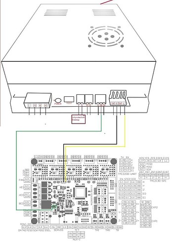
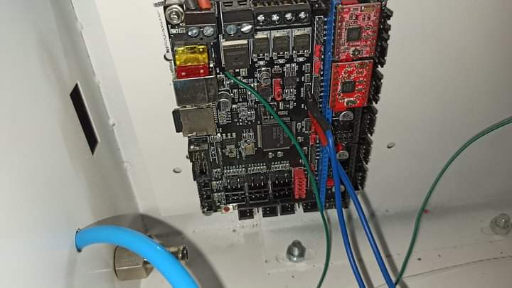
so if you want to connect you makerbase DLC32 v2.1 to your laser power supply . you solder the ttl(N on laser power supply) to the left leg of the laser connecter mosfet make sure u use the left leg . then take the L connector and connect it to the SCL pin (for I2C) then you are done no need for external control using variable resistor .
have attached my connections picture. now can use lightburn to control your laser power
in short
ttl output of the DLC32 → IN of the lps?
Along with SCL → L of the lps?
Is this ttl output of the DLC32 → IN of the lps?
Along with SCL → L of the lps?
I didn’t know it was configurable like this…
The standard way to connect these in a K40.
I’m not a fan of the potentiometer game, so this is nice to know… Is there any other configuration required?
Thanks…
![]()
no other configuration and yes ttl is your N and SCL in your L of UPS
That’s great… I poured over the documentation but couldn’t find anything like this…
Where did you locate it?
What firmware are you using…?
![]()
im using grbl 1.1f and this can be applied to all other boards like the skr 1.3 ,makerbase sgen_L etc just connect the left leg of the mosfet to get ttl then you make changes in smooothieware to correspond with your connection the on off (L) part is easy as you can simply use any freepin on those bigger boards
What do you mean?
There is source code to change?
I have one of these boards, I’d like to wire it up to the OMTech and see how it works…
Seems that it’s more complicated than you first stated…
Thanks
![]()
Is the left pin of the mosfet the gate? If so, it’s inverted from the output… and feed to IN? This does not make sense since the spindle is pulled to ground allowing supply voltage flow through the spindle.

Would you have the modified source to re compile this available?
![]()
“Harness” has been used to describe electrical wiring assemblies for 7+ decades. It is analogous to the set of leather straps used to guide horse teams. You don’t want to have to use single straps to hook up a team, so you build assemblies of the single straps that are quick and easy to use. For our laser engravers the use of the word harness is a bit of overkill, but it’s accepted practice.
Not certain why the wiring to a K40 is that complicated…
IT IS NOT!
I use external 24 V DC pws to supply the power to the MKS DLC32
A- 1 cable connects from (-) of the Spindle to the L
B- connect the G from the external power supply (24 V that powers DLC32) to G of the Laser power supply; in my case the 2nd connector to the left of the L.
That is all.
I am leaving the digital keypad to control the MAX power output that LB can use as 100%
and my 42 = 15mA; 35=12mA
wiring K40 is NOT complicated…
Cheers
Are you able to get PWM control from LightBurn with this approach?
I can Cut and engrave pictures.
I can see my Ampmeter getting variable power consumptions.
When cutting, if I use 100% in LB, my laser will go to the MAX of whatever I set from the OEM digital board.
If engraving, I can see the Ampmeter jumping all over with different consumption.
So, I would say yes.
If you refer to the schematic in post 34.
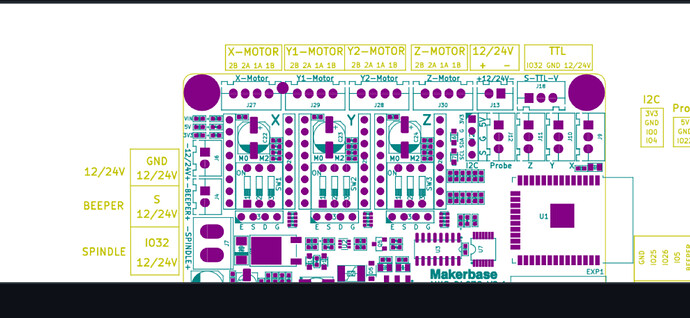
LC-0 is the pwm output from the processor. It is available at J18-3 (J18 pin 3) and inverted, via Q1 to J7-1 which is the spindle negative connection. If using a spindle, this completes it’s ground path. this pin becomes grounded.
Simple explanation, J7-1 pulls the L input low enabling it to lase at the IN values current level.
From this, he’s manually setting the current limit via a digital keypad.
This is, although a bit abstract, basically the standard K40 wiring. It’s operating the tube like a ssl.
Anytime you can control the current level by some manual option like this, you’ve lost software power control, at least with dc excited lasers.
I wouldn’t do it this way, but it’s not mine ![]()
Ever wonder where the nomenclature of plus and minus came from?
![]()


