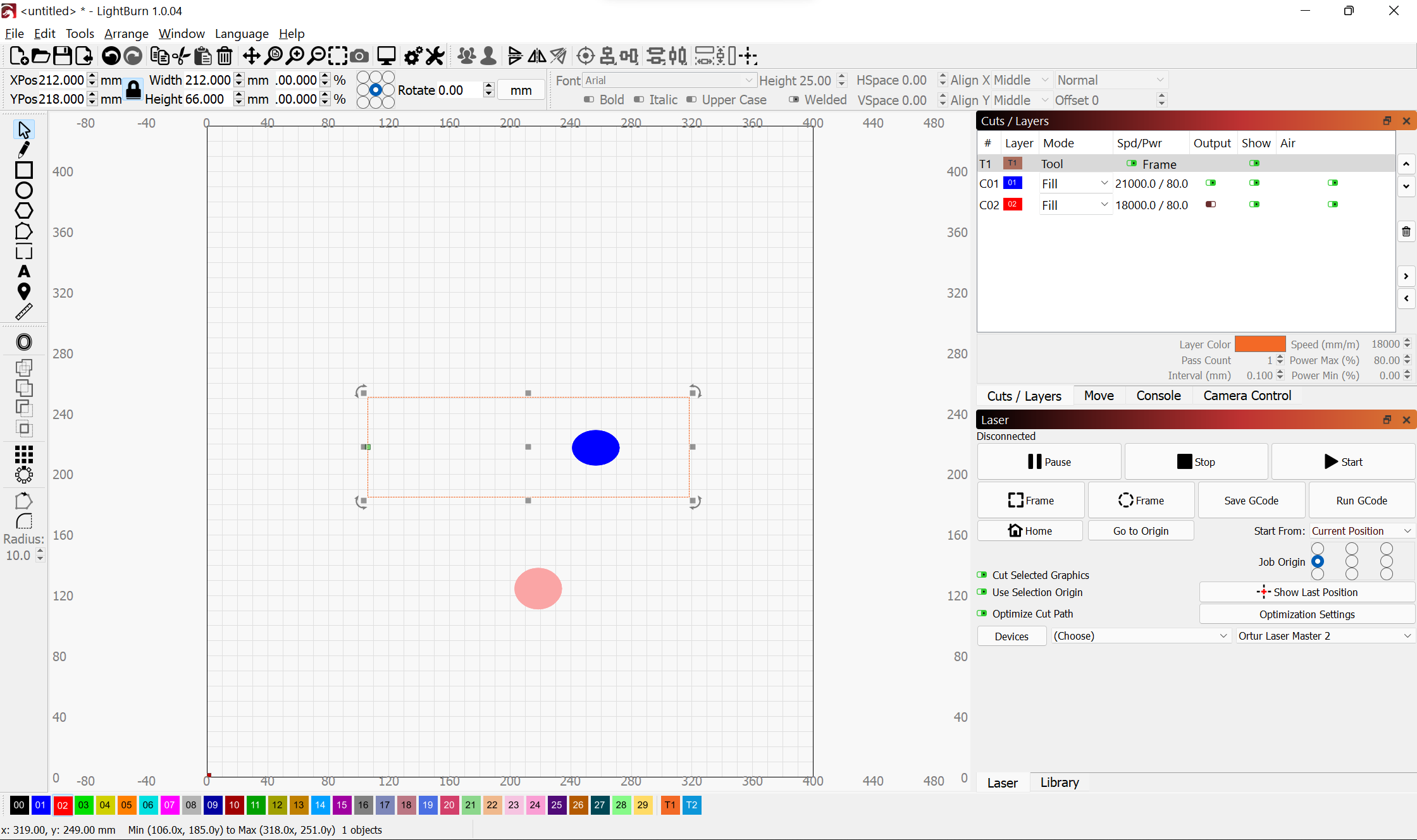
Is there a way to either manually place the green origin square, or omit layers from affecting the position of it?
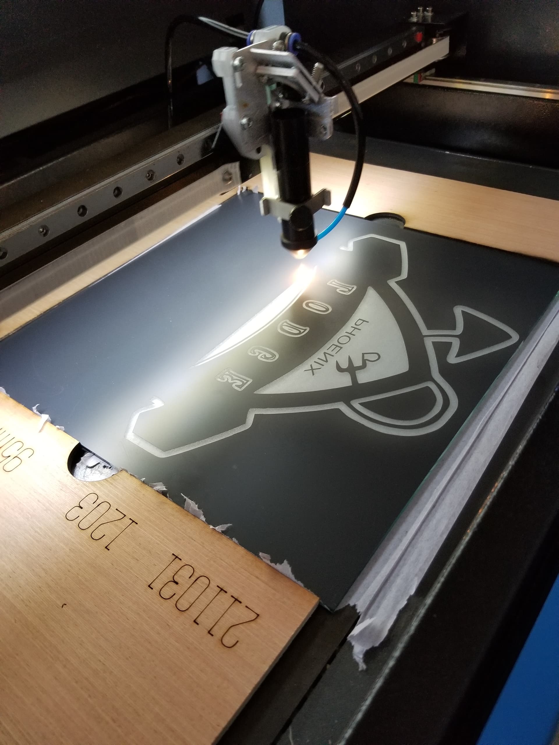
The attached image is an example of a problem I run into all the time with Lightburn that leaves me feeling irate with the software. I have a tool layer that is referencing a physical jig on the laser bed. The jig indexes along the sides of the bed, and I have a saved position that moves the laser head to the exact left center. I have one layer that needs to be cut, and one layer that doesn’t get cut but I need to hold on to. Is there a way to either lock the green origin to the left center of the tool, or have LB not factor in the layers that I’m not cutting? There has to be something I’m missing here because user defined software origins is basic in every other CAM package I’ve ever used.
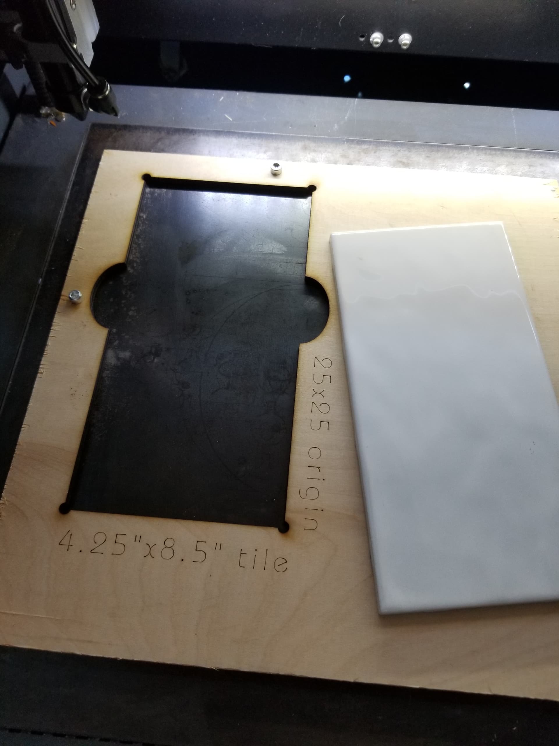
Set it to “absolute coords” and everything should be fine. I have set my machine to absolute coords, made a template with x + 50 and y + 50 and everything works fine. is that what you want?
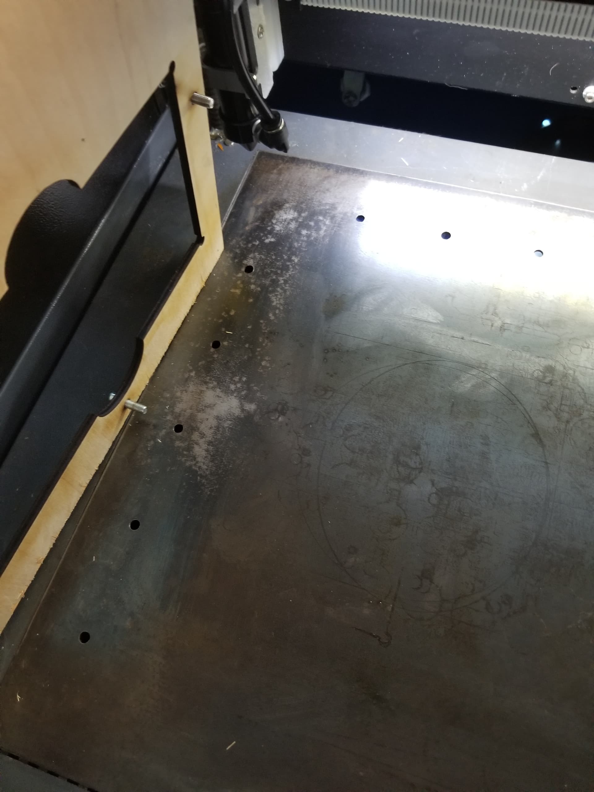
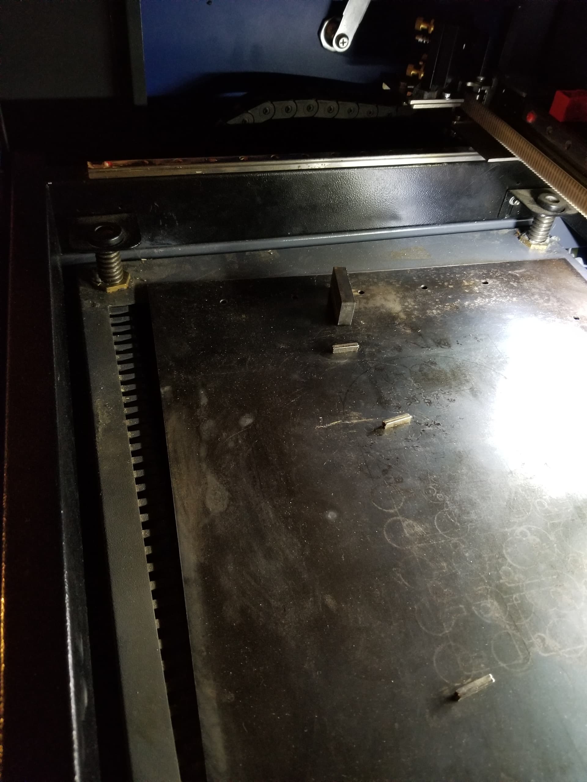
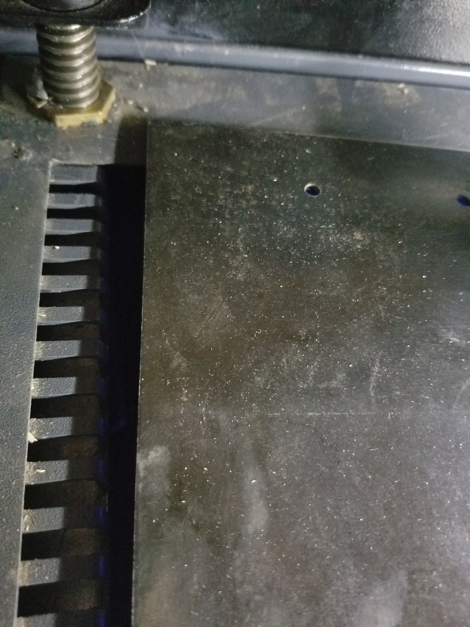
The plate has a ‘pressed’ area where the original aluminum supports for the honeycomb existed. When removed there is a nice notched out area where the plate can sit.
I’m trying to explain this and it’s a great question…
Though a photo would be better, even if it’s kind of dark out.
Threw out the honeycomb and support, purchased a chunk of ‘rolled steel plate’ at the local metal supply ($12), used that ever since. Fit’s pretty snug.
I sprayed one of the chemical to be able to mark metal with a laser. Drew up a group of cross hairs, one every 50mm. Let the machine mark it and drilled them in the drill press.
The next alignment holes will be in the outer frame, outside of the work area. Will give me more usable area.
@DaveP1 While you’ve gotten some tips I don’t think anyone has tried to answer your concern directly. Frankly, I think this is a bug and related to an issue I brought up in a different topic where the framing functionality references even layers where output set turned off.
@gdrennan Given @DaveP1’s specific needs I don’t think using “Cut Selected Graphics” alone will get him the desired effect as he has objects outside of his burning area but within the workspace that are affecting the origin.
He will have to use the “Use Selection Origin” to enable this.
With Cut Selected Graphics on, if you want to include the tool layer for framing, then you would need to select it along with the other objects to be Cut.
Also Frame would need to be on in the tool layer.
I use this all the time with jigs to burn specific locations in the jig.
Thanks everyone. I rarely used the Cut Selected Graphics feature so it hadn’t occurred to me to experiment with it. I’m okay with needing to drag select the tool layer to get it to calculate the origin correctly. I was able to get this workflow to work correctly with some of my production files, so I’m content with this solution. Thanks again.