Im running lightburn on a Windows laptop controling a Genmitsu Pro 4030 (grbl) with a Laser Tree K30. Im trying to engrave Rowmark ADA signs. I did a material test and everything looks fine. I pick a speed (75% power, 300 mm/s) which should be fine, however when I use the EXACT same settings, and passes, it doesnt engrave correctly. Ive done this multiple times and wasted materials. Bottom was material test… top was what it actually did .
Hi Dale
Does seem you used a different fill method for the text
Offset fill? Flood Fill?
Could you share with us the LBRN file project so we can take a look?
From the image it looks like it burned too much, but I could be wrong.
If you do a new “Material Test”, what is the result, the same as the previous test or the same as the engraving?
I tried 3 different material tests and they are fine. Its only when I go to engrave the job, does it differ. And the job had the EXACT same settings as the material test. I dont know if it makes any difference having a laser external driver adapter for the laser power has anything to do with it or not. Ugh, I just tried again with same results.
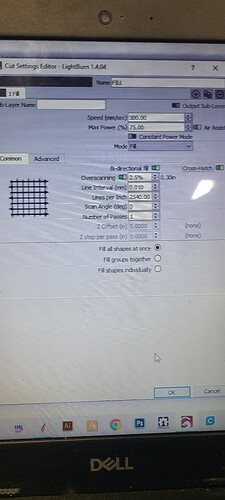
can you show what the layer settings you are using for your project and the layer settings AND the material test settings are? It looks like you don’t have overscan turned on in the project
In your material test, there seems to be no gradient. It is either all or none, and nothing in between.
Do you have Constant Power Mode turned on in the Material Test?
Yes, I tried overscan on and off just to rule it out. No i didnt have constant power on.
Attached is an image of the engrave settings. As well as an image of the material test
I only have 2 layers. 1 is only a reference square that is not to be cut/engraved, and the 2nd layer is the text that is to be engraved. Rowmark is capable of doing gradients but all I do is 2 colors. We typically engrave off the top color to expose the lower acrylic color. I have to get this fixed before moving to images and gradients with the laser.
Just for clarification, the text in the original post is supposed to be white which is the underlying color. And it was to be filled in.
You are, in effect, removing the microsurfaced acrylic to expose it’s base.
Rowmax is designed and all the supplied data is for a co2.
Laser-Reference-Guide-Revised-July-2021.pdf.txt (144.2 KB)
Acrylic absorbs the co2 IR wavelength very well, not so with a visible light laser.
The Reference guide…
Using the marked 30W reference, 70mm/s@30% with an interval of 500 dpi.
This would be a good basis to start, but since the absorption rate between the two frequencies is vastly different, it will undoubtedly have to be adjusted.
The materials test does each square individually. Heating occurs across each scan, a small area, such as the square of the materials test square may not have the same heating and retention characteristics as a larger scan area as in your text.
The previous line, in the text scan, has a relatively long time to cool down, unlike the small scan area of a square in the materials test.
You are also using a very small interval, so you could be making multiple passes over the same general area effecting how the material is damaged. This depends on spot size, which no one seems to stipulate for your laser.
The suggested setup seems to indicate that they are moving slower, using less power and a larger interval (lower dpi/lpi) … I’d suggest moving more in their recommended direction.
Keep in mind that a visible light laser cannot damage acrylic… you are heating the color doping materials within the acrylic to apply an indirect heat method to damaging the acrylic. Probably why there is no mention of visible light lasers being used on this material by the manufacturer.
I have similar experiences with my fiber using stainless steel, the materials test sometimes needs to have larger squares to correctly portray the actual results on a that scale …
Does this make any sense?
![]()
Sorry to step in.
Try 300mm/s 57.5%.
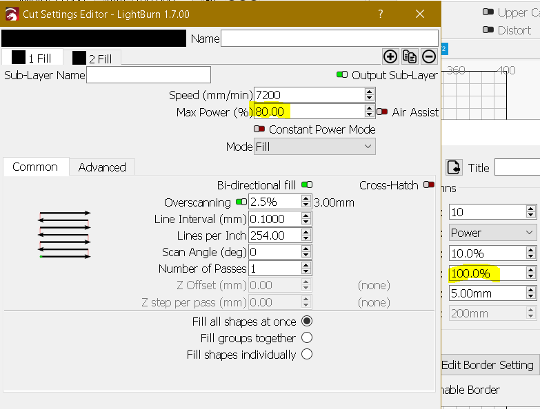
Likely your material test is giving you 100% = 75%
When you edit your cut/layers for material testing you have to set power=100% for full scale.
After that you can do an interval test to find the best value for your laser spot size like @jkwilborn said.

Are there guides on the interval test?
The material test allow you to vary the interval and it gives you labels…
![]()
So if I understand you right, it has to do with the acrylic heating and cooling at different rates due to proximity to last pass? Even if settings are same.
This is how I’m reading what I can see. I’m looking at what the laser is doing to the material.
I have a microscope and a digital magnifier to look more closely at how the materials are being damaged. I might not be able to really see things as well as I’d like, so keep that in mind.
With my fiber, when I’ve done a materials test that is relatively small compared to the actual artwork area, I can get the different or wrong colors produced… Metals suck heat away.
On yours, I’m thinking the plastic is melting via short the short quick laser passes in the materials test… when your passes get long, that allows more time for the top coating to cool down… this can easily change the results.
Besides interval, which I think could also be an issue, that’s about all I can think of that will do this…
I’d suggest values based on the vendors specification… for a start… along with a larger area in the materials test.
I’m guessing here - some experience and helping other.
![]()
This topic was automatically closed 30 days after the last reply. New replies are no longer allowed.


