Before boring you with my doubts let me wish you all a Happy Holidays!!
Edit: somehow I forgot to mention the material is black K-Line
(a material with a more rigid film on the outside but on the inside is a type of foam)
In the past I cut this material 5mm thick with a 5W laser diode. It wasn’t an exemplary cut, but it was an acceptable cut.
At the moment, I’m dealing with the same material, but with 6mm (because the sheet of material I ordered in 5mm arrived with 5mm on some sides and 6mm on others.)
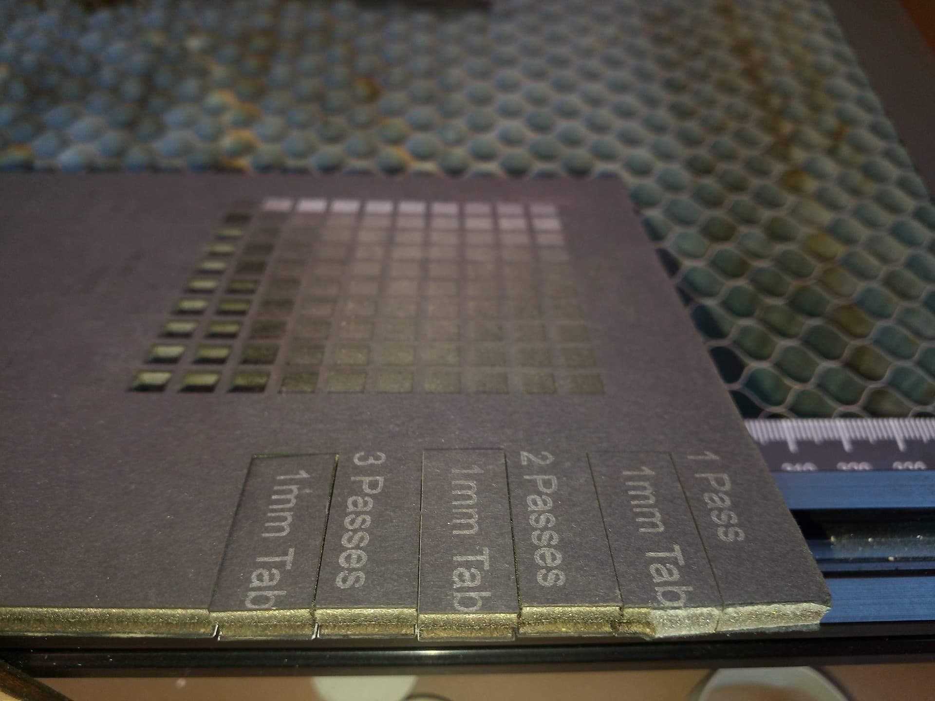
I’ve already tried several passes with different powers and speeds and it didn’t work because it always ends up melting the internal foam too much due to the heat created during the cut. If you use air assist the situation will get worse.
In one of the attempts I made, I managed to get a very acceptable cut up to 3/4 of the thickness of the material.
This gave me an idea, which was to make a first cut on one side, turn the sheet of material over (mirroring the work in Lightburn) and make a second cut.
Now my doubt lies precisely here.
My idea is to mark the bottom and top center of the material, in lightburn select the bottom center as “Job Origin”, with “absolute coordinate.” selected, send the laser to “Job Origin” and align the lower center of the material here, send the laser to the upper center and align the upper center of the material here and send the laser again to the “job origin” to check if it remains aligned in this point.
And with this method, make the cuts on one side and the other with the hope that the cuts coincide.
What is your opinion? Or is there a simpler way to do this?
If it’s difficult for me to understand (and I wrote it) I don’t want to imagine the puzzle I just created for you…
Ok, you can call me the Grinch and I won’t take it the wrong way.
What you’re proposing might work. I think you would get a little more precision if you have a fixed position fence to register against. That would take one variable away.
As long as your material is square (90* edges, not necessarily a square) you could use print and cut using the corners away from the fence as the targets.
Hi @thelmuth
Firstly, let me thank you for your patience in reading my entire description of the “problem”
The material will have to be cut by hand with a square tool and a cutter, so it should be more or less square. (If the laser machine cuts from one side to the other, I would cut with a laser but at the same time I would no longer have the problem of cutting the material I have.)
I tried to use this feature but as soon as a circle appeared that didn’t cover the corners of the drawing (I deduce it to indicate a reference point) I gave up because it was too late and I had to leave.
But yes, I also considered this way, which probably works as well or even better, but I still don’t know how to do it correctly.
I have to watch some more videos on how to do it correctly.
With print and cut you don’t have to use actual targets engraved/drawn on your workpiece. You can just use the point of the corners to align the laser. I only suggested this as transferring a center mark to both sides of the workpiece may be problematic and a known, fixed point, like the corner may be better.
Even with your suggested method of using center lines, having a fence parallel with your X axis will eliminate the need to align on the Y axis. Just place the top or bottom against the fence for both cuts.
One of the issues that occurs when you flip a work piece, is that the cut/image has to be centered symmetrical to both sides… Usually not as easy as it appears. Print/cut may fix some of this, but I don’t know how it would help when you flip it over and have marks to align with. In the MW video he punches through to leave marks on the reverse side …
I’ve done this with pcb’s.
It also depends on the precision you need. The eye can easily pick out a 1/4 of a mm of misalignment on most things.
Thank you all guys!
I definitely have to watch those videos and learn more how to flip the piece and make de cuts coincide when the job to cut is not symmetrical.
As soon as I can, I’ll share the file here just to give you an idea of what we’re discussing. After having taken the trouble to read everything I wrote on the subject, this is the least I can do.
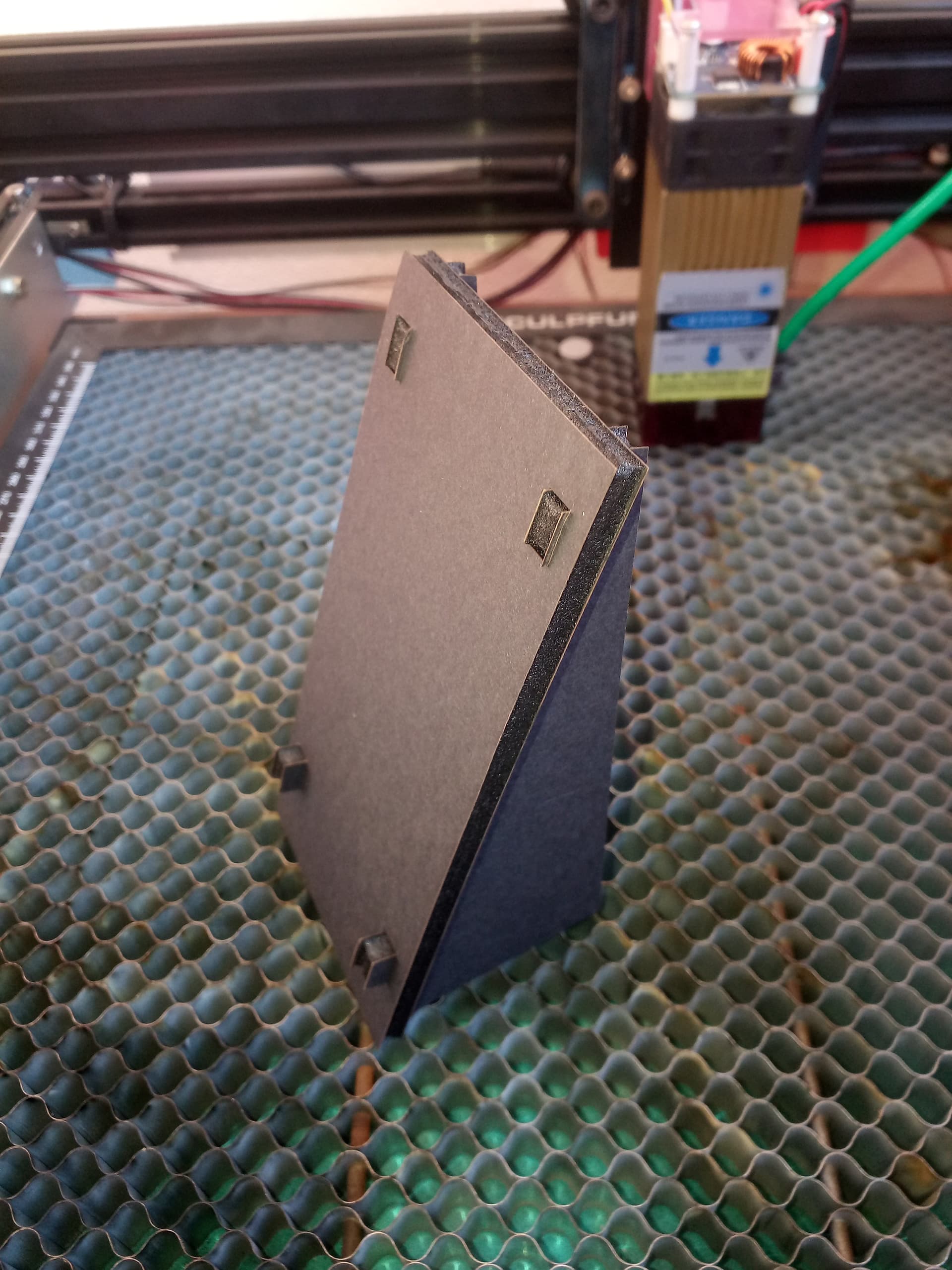
As promised, I leave the file and a print screen of the work here. Through the print screen you can see that I don’t have much free space on the sides, space that ends up being occupied by the protection of the laser module which measures 40 x 40mm. Tile Display Stand Group Natal2024.lbrn2 (19.7 KB)
The Christmas presents had to be delivered without the displays stands but patience. They will be delivered later.
I currently have a back pain (a health problem) which prevents me from literally lean over on the subject.
I can work on the computer but lean over the laser machine to place, adjust and remove parts, no way.
So I’m watching the videos you suggested and drawing conclusions.
Took me a few minutes to figure out why you had 10mm tabs for a 6mm board. Then I realized what the final position of the stand was.
I think your layer cut order is backwards. The slots should come first while the material is still supported. Then cut out the 6 pieces that make the stand. Finally comes the box cutout (00 layer).
I fail to see the purpose of the 00 layer. Once the 01 layer does its work, the pieces would have dropped and you are done. It also saves about 30% in the cut time.
I also wonder why the Multi layers. That is just complicating what is a very simple project.
A picture of the stand assembled would save you that time. Sorry, my fault.
Yes, you are absolutely right. this file comes out from the PC where I make all the design then i transfer it to the pc connected to the laser where I make the adjustments as layer priorities and tune power and speed, etc…
So, this is a job to make two tile stands at the same time.
The layer 00 is to cut a frame where all the pieces stays together and can be packed in a box preventing the pieces moving damaging the tile or the male slots. (I have to take some pictures of what I achieved until now).
This layer is also the interior dimensions of the package box and the piece of material to be cuted.
Let me me explain it to you.
First multi layer, first cut without tabs with the second multi layer disable.
Second multi layer, after flip the piece on the laser board and mirror it in the software, I enable the second multi layer with the tabs and disable the first muti layer.
Remember, my laser can’t make an acceptable cut in this material without making a mess if not flipped.
It’s not plywood, It’s K-line. I don’t know what is the right name but, as I described in the beginning, it is an interior kind of synthetic foam and melts with heat.
I don’t use plywood because it looks to me unsightly with black tile. Maybe if painted with black spray… but I am kind of lazy and the less work, the better.
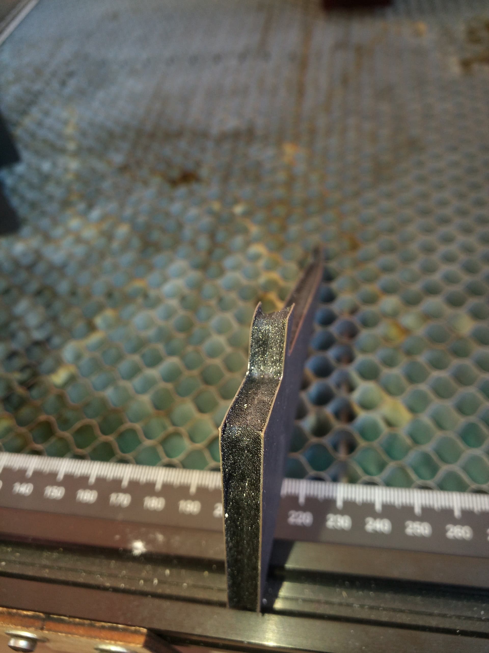
The problem is that the material I received is 6mm thick instead of 5mm thick and this makes a very significant difference.
Especially when a cut concentrates a large amount of heat in a small area.
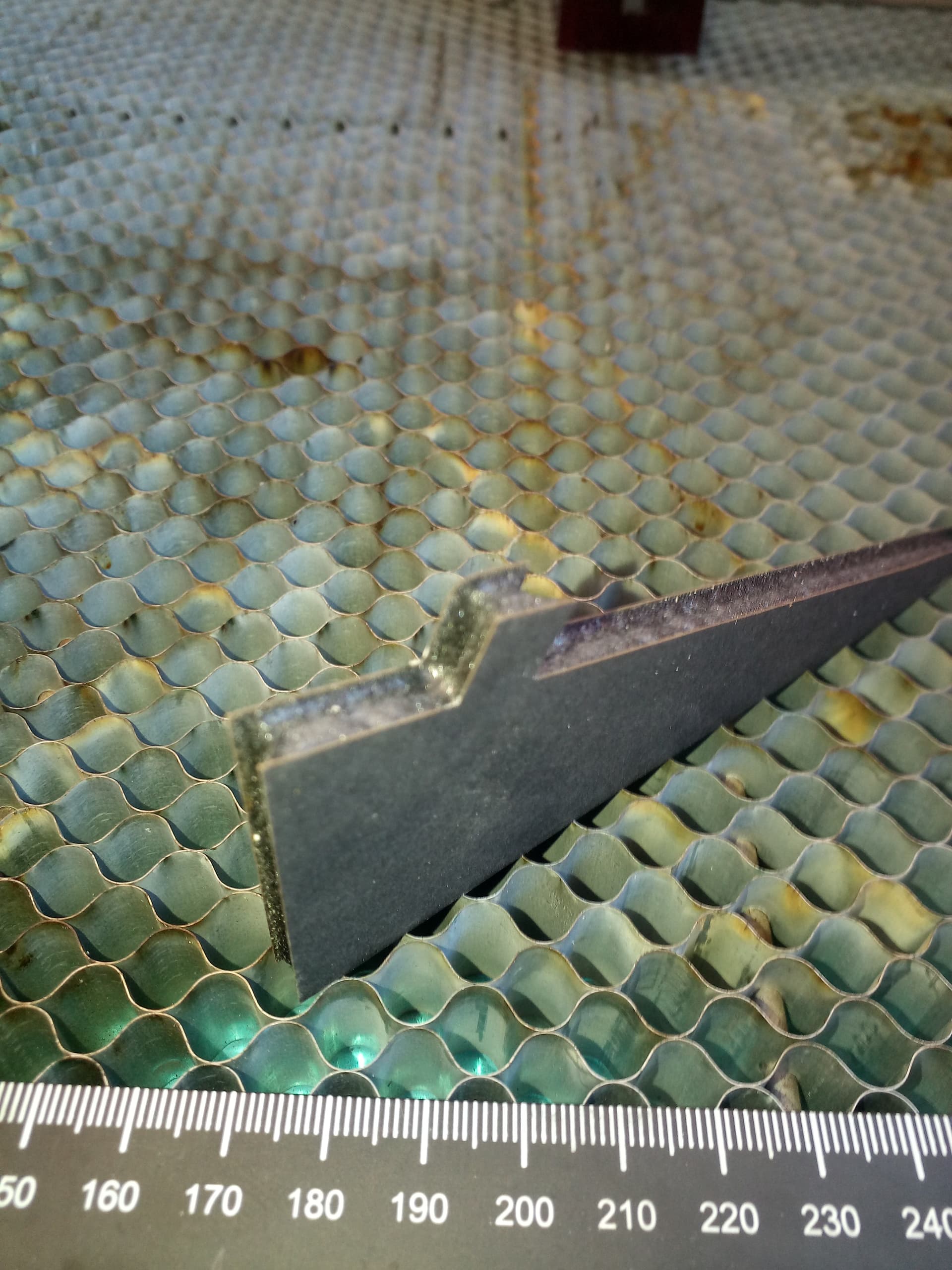
The result is that it melts the rigid foam inside and ruins the final appearance of the cut.
Therefore, consider that the only chance of achieving an acceptable cut is to use a technique of making half the cut on one side, turning the piece of material over, mirroring the image in the software and making a second cut.
However, this is easier said than done because, here is the origin of this topic, it is necessary that the cuts coincide on both sides without deviations.
As @MikeyH suggested, plywood would be an alternative, but where I buy plywood they have low quality standards.
Just last week I saw a sheet of 3mm plywood where a considerable area was just white glue.
And I can’t afford that kind of quality and throw half the material away.
Not all plywood reeks of this quality. You could try different sources. I have no idea how the cost of laminated foam compares to a decent Baltic Birch plywood. I refuse to cut anything with plastic in the name is why I suggested plywood.
Your images really show this problem very well (Do the rest of you see why we ask for images?). I do not know if you tried more air or less air, but I think the cooling effect might make a difference. Maybe even add some sort of coolant mist (distilled water) to the air flow, adjusting power/speed to compensate? Maybe attack the problem from a physics rather than an engineering point of view.
Unfortunately, from my point of view, Portugal exports all the good wood and derivatives it has and only keeps the leftovers. Good quality wood exists, but it is very expensive.
It will most likely be cheaper to import sheets of material derived from wood (possibly Portuguese) via eBay.
I know that the images help a lot, but at that time when I was in a hurry to solve the problem, there wasn’t enough time to do everything right. (Take decent photos with my “3310” (this is what we call cell phones that aren’t capable of taking good photos on the first try ) and could anyone have already been through the same thing and have an idea how to solve the problem.
I’ve seen the videos, which I really appreciate, but there’s something in common in the videos, which is the ability to cut the material from one side to the other at once.
And this is the essence of my problem, with this material that came exchanged, I need to do half the cut on one side and the other half on the other…
Probably using the corners of the material (which must match the dimensions of the black layer) as crosshairs, the print and cut function will work but I will have to test it at another time when my health allows it.
The material in question (K-Line) came from a professional stationery shop, not from a DIY store as plywood.
I have to call their attention next time!
My recovery is slow but I believe next weekend I will menage a few more tries and tests.
Oh, about that tip you left about air assist and distilled water It’s not doable because the top (and bottom) surface is a kind of pressed paperboard.
Furthermore (there have been many attempts and I don’t precise remember them all) but I have the idea that the assisted air makes it worse, probably because, as the cut does not go through the material, the only exit left is from the cut just made and upwards, dragging the heat and melting even more the internal foam. I got the impression that without air assist it works better.
Hey, but thank you very much any way. I’m always appreciate new ideas!
Of course it helps, Thank you.
It is too much sheets for me but have you been purchased for you? How is the quality? It is the most important because low quality is a waste of money that I can’t afford.
")