Maximum range of working area for rotary working mode (or linear?)

Greetings!

We are trying to move away from EZCad and test working with Lightburn, but we cannot create the same workspace as in EZCad.
At the moment, we have a working solution in Lightburn that can perform marking in a static area (without moving the guide; the laser is mounted on the guide, the table is fixed).
All these components came to us as ready-made equipment with a Raycus 30W laser + control board + work table.
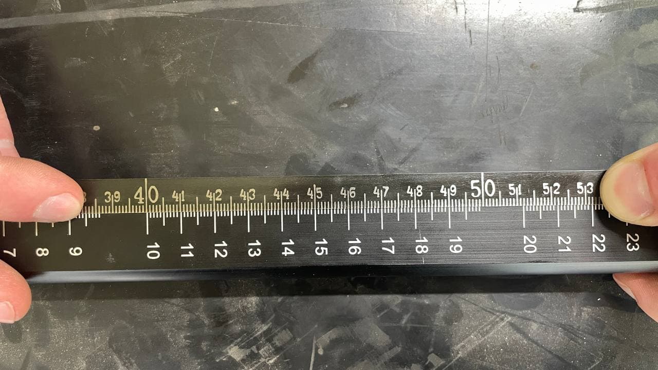
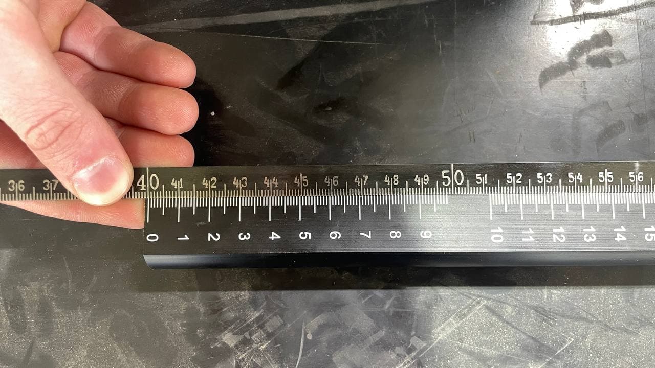
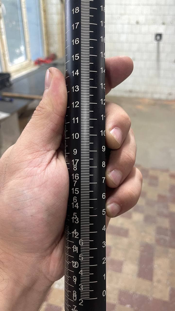
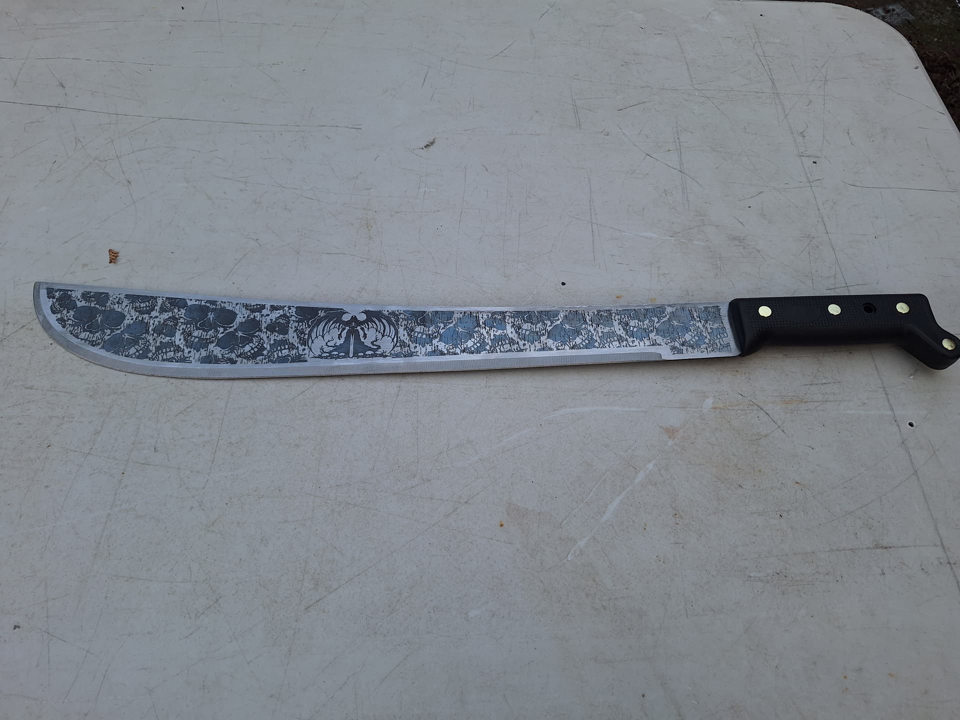
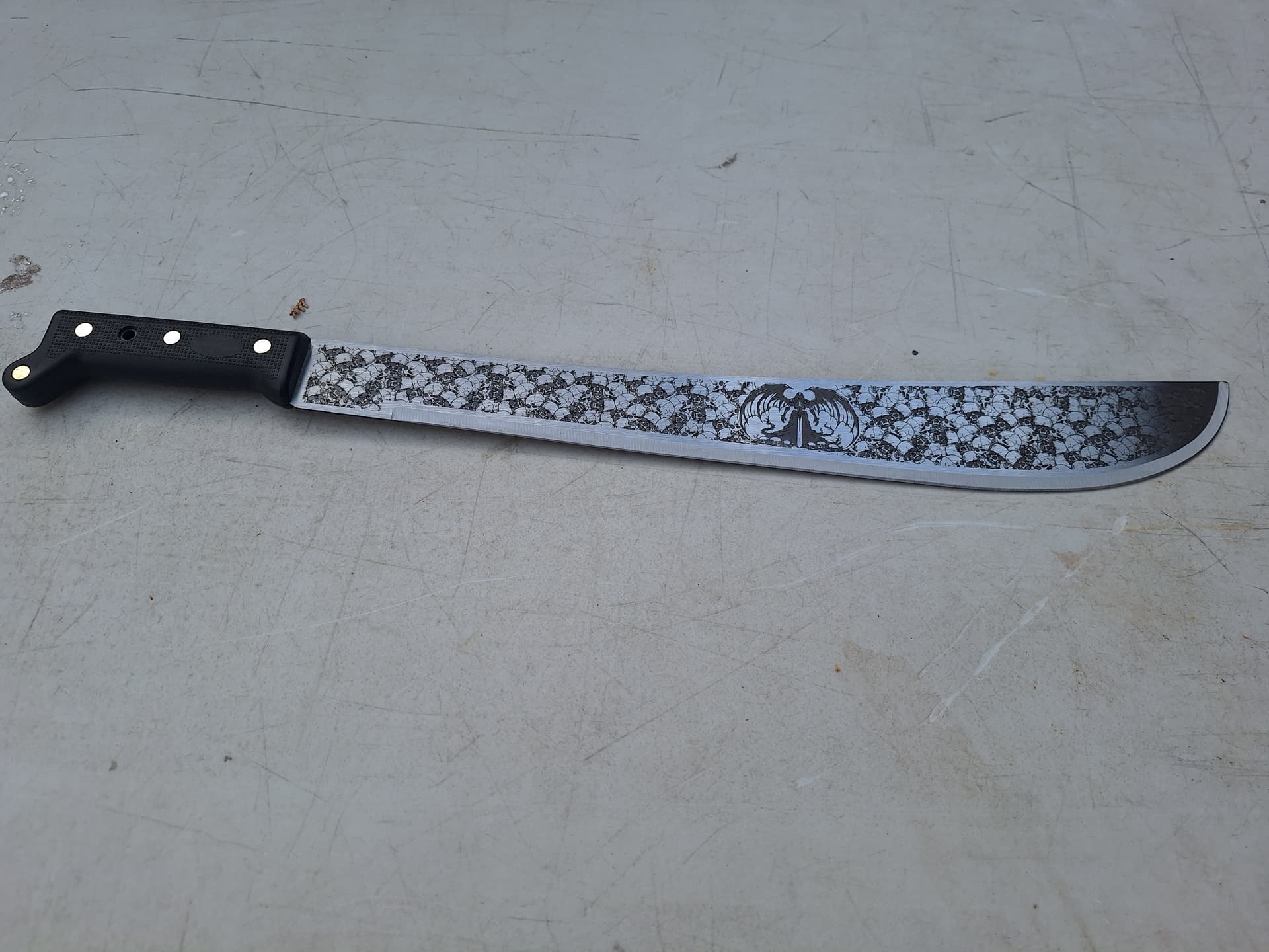
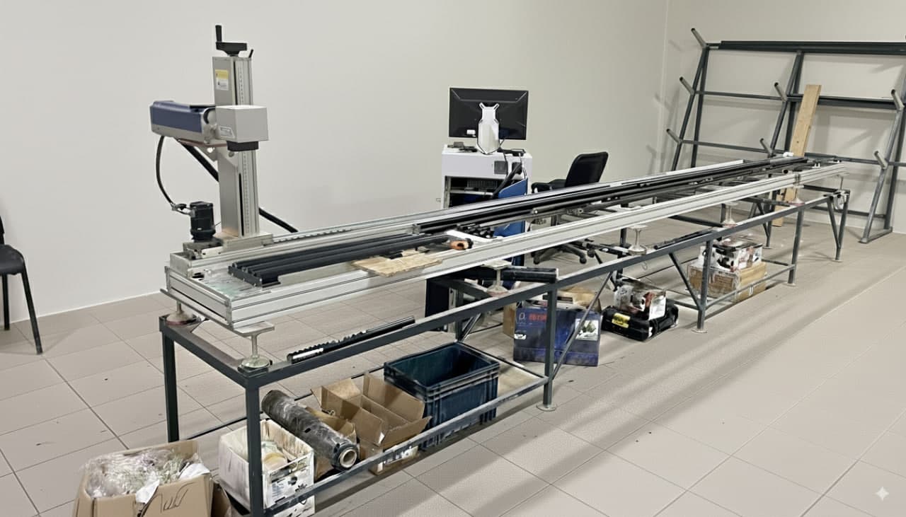
We mark full length rulers up to 4.5 meters long. In our case, a linear actuator with a length of 4.5 meters is used. It works fine with EZCad in operation mode, but as everyone knows, this software is awful: it freezes during the marking process and hangs on large projects.

To control the laser movement, we used the SplitMark2 plugin in EZCad.
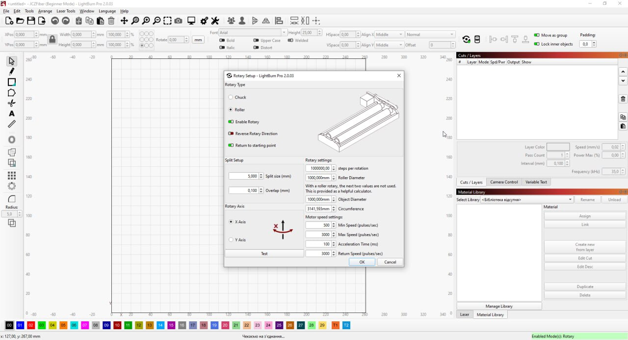
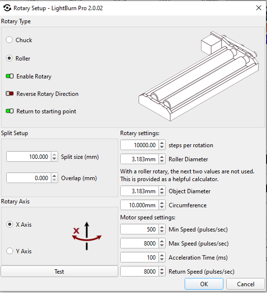
We tried using the Rotary (Roller/Chuck) movement mode for control, but we ran into a problem — we hit the limits of the maximum parameter values.

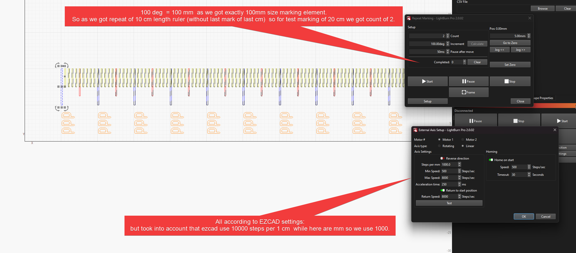
Since there is no identical parameter set between Lightburn and EZCad, we recalculated the parameters mathematically and entered the values. The mechanism started working, but only within 1 meter, while we need 4.5 meters. We cannot set values larger than the current ones…

Perhaps we chose the wrong working mode in Lightburn, or maybe there is a way to increase these values?

I would be very grateful if someone could advise…

We would really like to use Lightburn to solve our tasks, compared to EZCad it’s like “heaven and earth”!

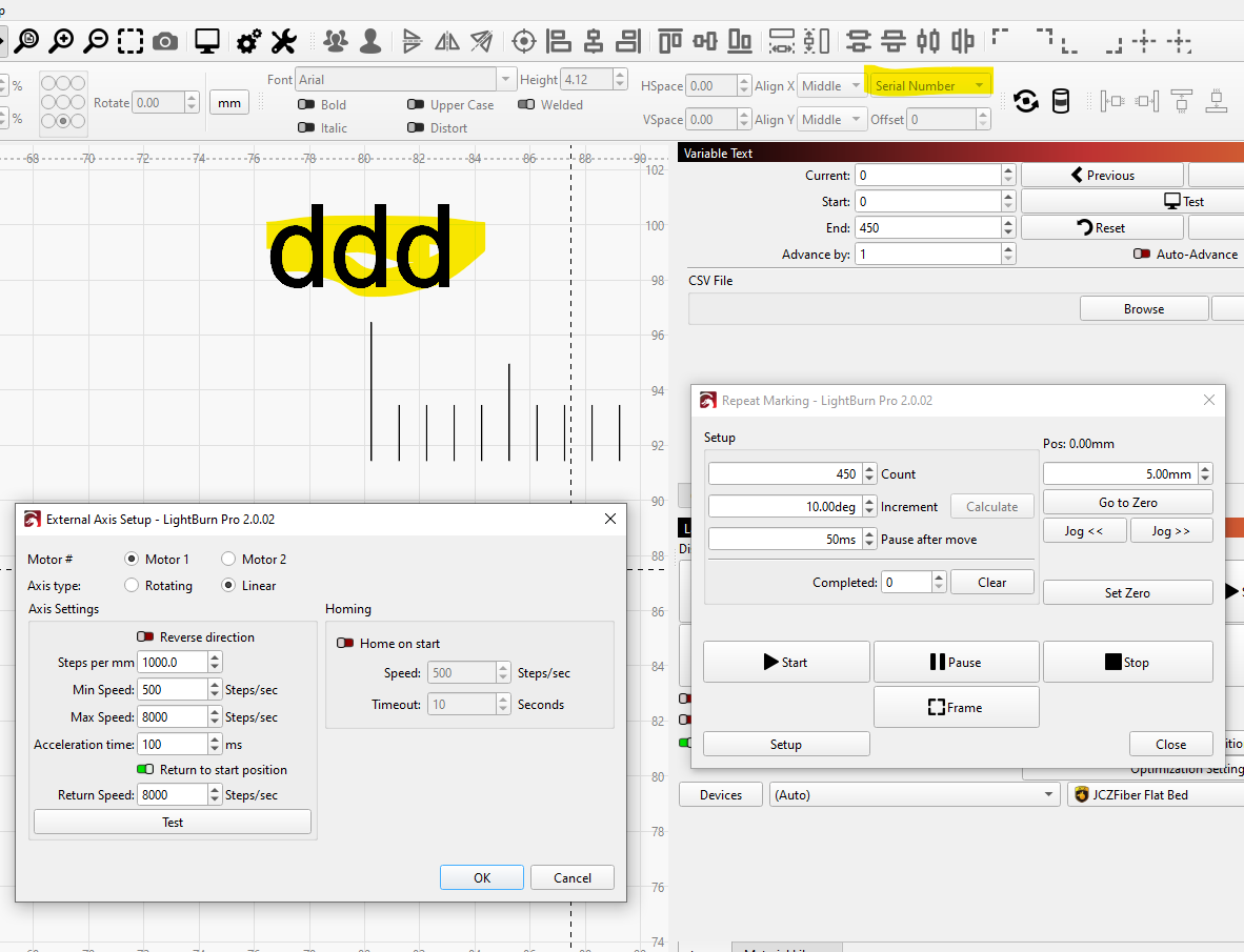
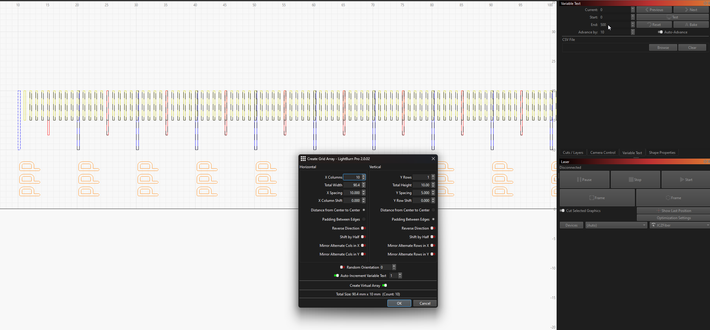
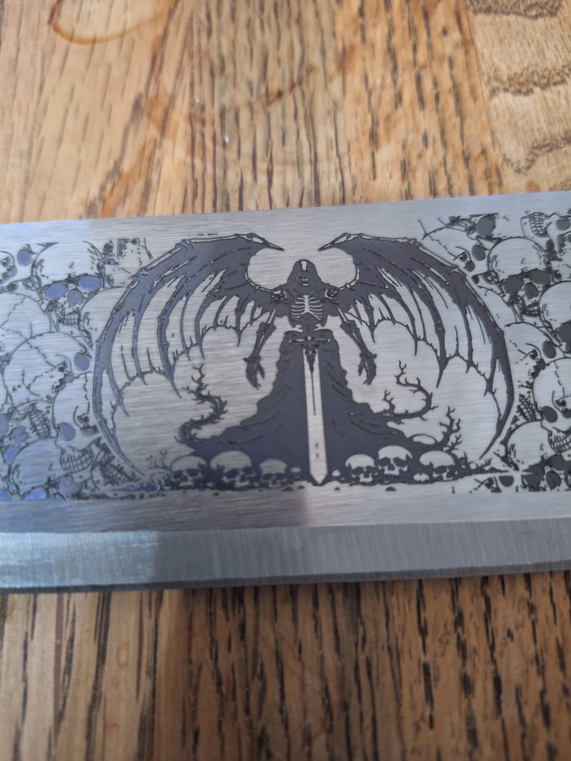
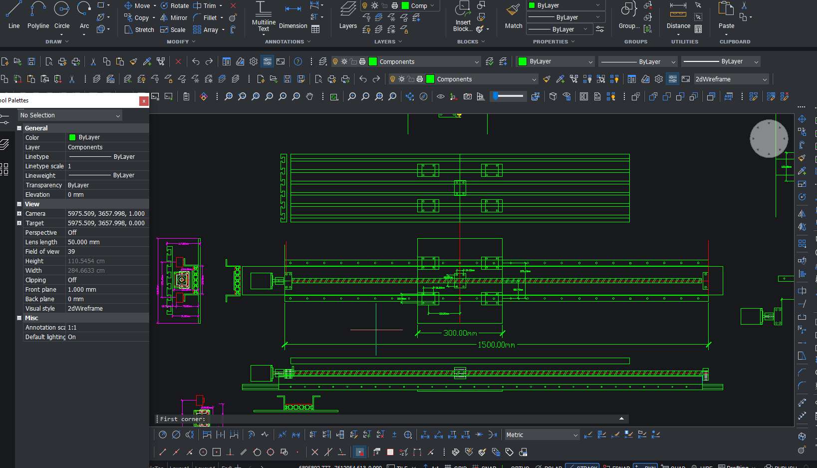
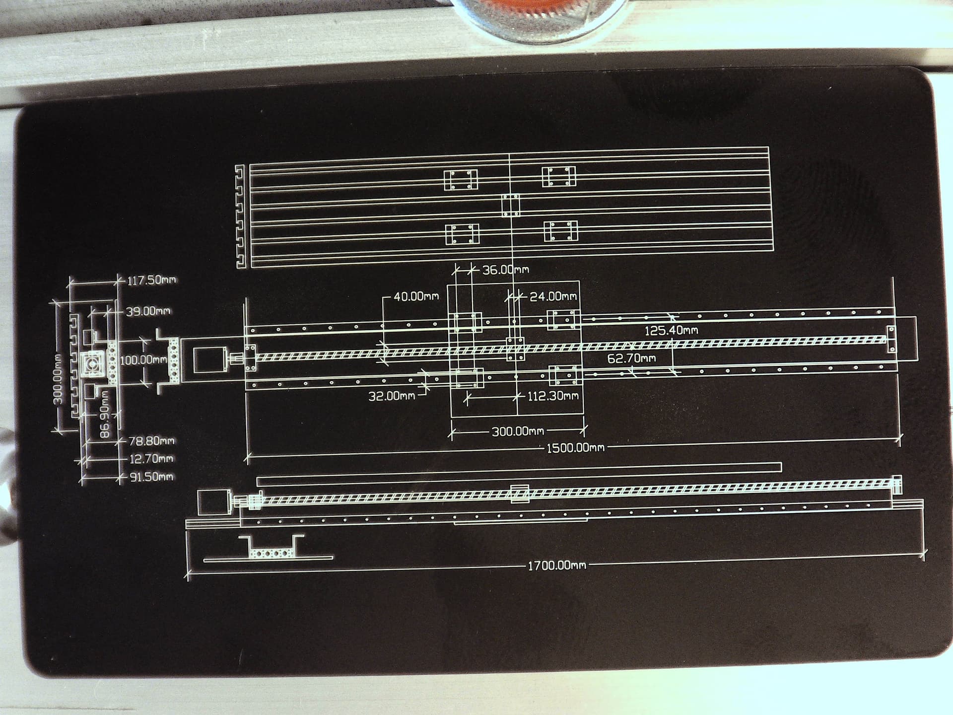
Here is a visualization of the working area:
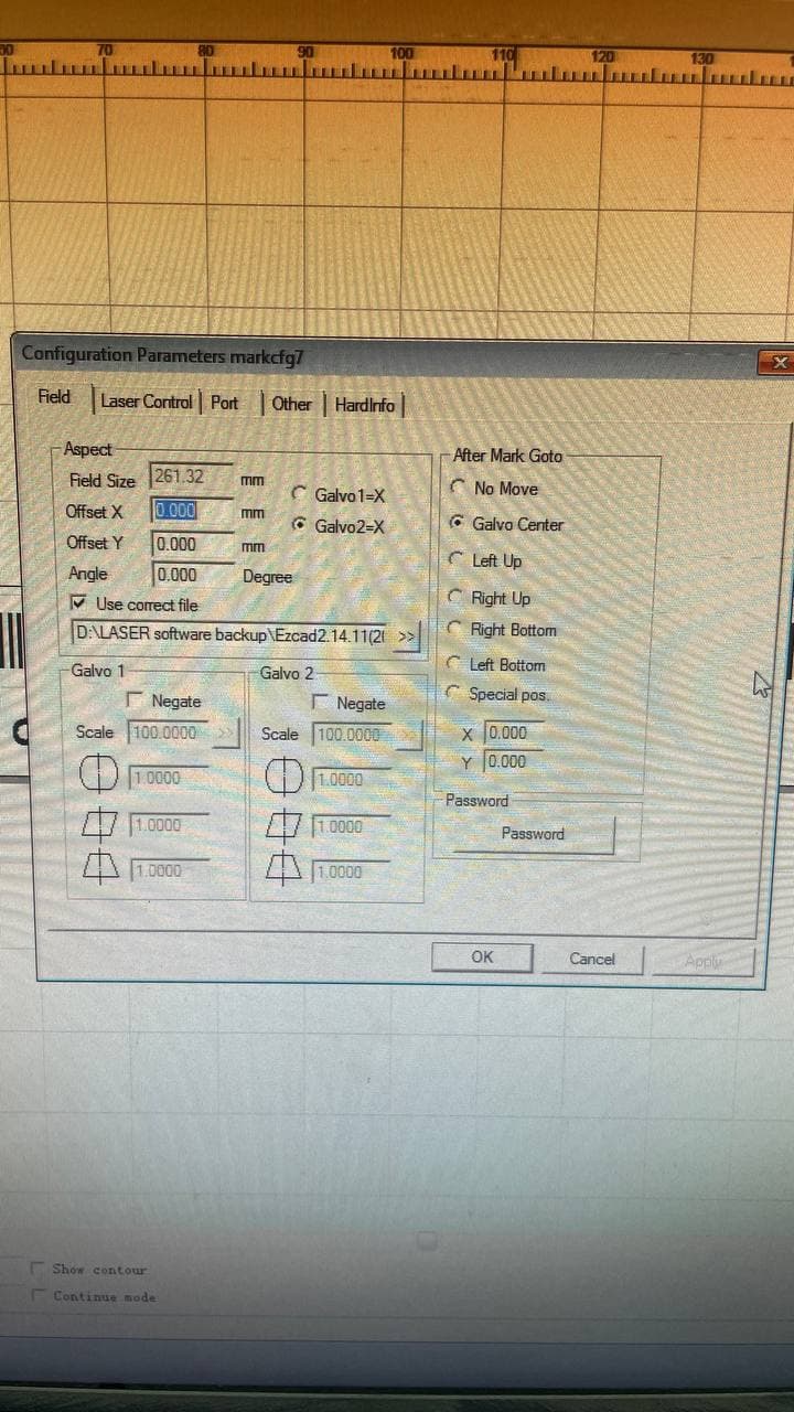
Ezcad settings:


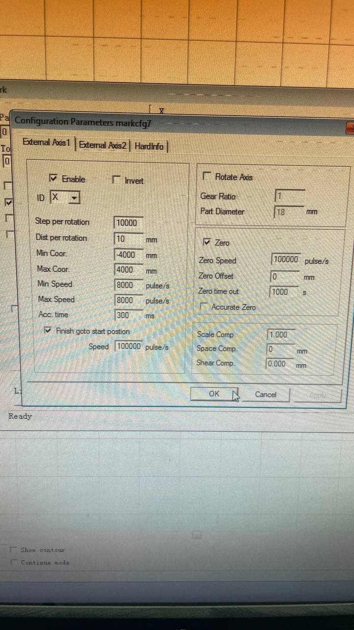
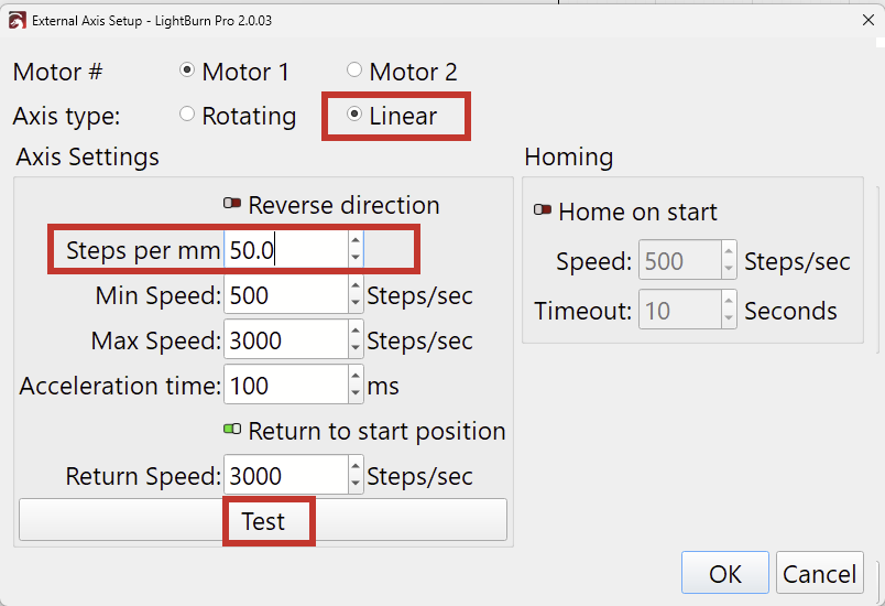
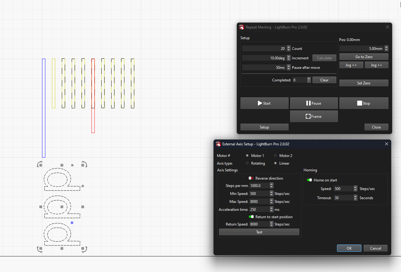
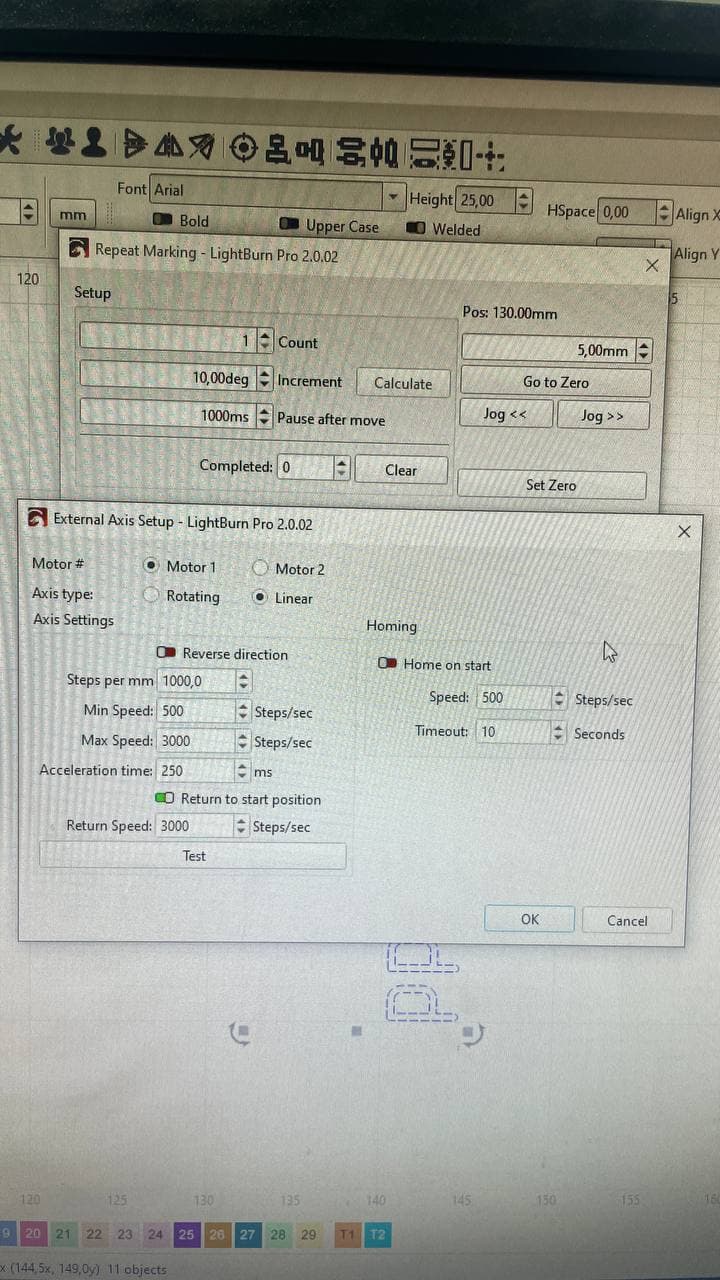
Rotary settings in LB:

Or maybe we are looking in completely wrong place for this fucntionality?

This looks like a pretty nice setup. Question, is this rack and pinion or belt ?
If you want to use a roller rotary setup, and using your ezcad settings, I would try this, based on your 10000 microsteps moving the laser 10mm, 100mm split (Max allowed with these settings).

The math works but I have seen parameters in ezcad that defy math so just my best guess from playing with cnc stuff.
LB allowed me to draw and preview an 8000mm long rectangle with these settings.

If it was me, however, I would use repeat marking and dynamic text to engrave long rulers.

Linear repeat marking a scale on my XY table, same principal.

Its rack.
Im not sure we need to 100% use rotary setup.
I made and app using maker.js to generate valid rulers with different length and product label after ruler (to fit iso and other standarts format in different cases).

So as result a got DXF with, for example, 4.5 m long scheme that freezes at ezcad (in any approach) and easily handled with lightburn (even x4 rulers with 4.5m length are ok here which perfect!)

But for now we fails to launch it to work with this size…

Is repeat marking allow marking long non duplicated element as single element with moving to single direction (X-axis)?
ezgif-5c7f997f892075

Looks like repeat marking is now working as required…
Needed to mark with next condifitions that is impossible to set dynamically:

  • Layer 1: Meter marks (0.75mm thick) and text mark like “1m / 2m / 3m and so on”
  • Layer 2: 1cm marks (0.6mm thick) and text mark like “1 / 2 / 3 / 4 / 5 and so on”
  • Layer 3: 5mm marks (0.5mm thick) no text marks
  • Layer 4: 1mm marks (0.4mm thick) no text marks

And based on size of rulers it can be from 0 to 2, 0 to 3.5

Is there ability to increase in software step per rotation up to 5000000 and diameter of roller up to 2000 ?
Thank you!

Yes, repeat marking will mark a series of numbers and evenly spaced tickmarks, you would need to run the logos and any other singularly occurring art separately. It is ideal for what you show above. Assuming you move 10mm per 10000 pulses that would be 1000/mm. in the steps per mm field The Increment field is in MM even though the field is labeled “Deg” Play around with this see what happens. As stated above, the math from a vendors setup in ezcad doesn’t always transfer directly to LB

Excellent idea, @Albroswift !

I just noticed the same and made an internal report, thank you.

When you change the Repeat Marking “Axis Type” to “Linear”, you enter steps per mm instead. The correct value here is expected to be within the limits.

When clicking on “Test”, the linear table should move 50mm and back if you entered the correct “Steps per mm”.

Well i made this project:

Settings for quick review:

And as result we got this gap between first and last element… gap size is approx is 1 mm size.

Here is settings of marking:

I tried to rework logic from 10 cm length dynamic ruler to 1 cm length:


And still got some “shift” troubles, you can set it between last mm of each cm gap is bigger than length of 1 mm…
.

I tried to play around with settings of interval and it fails even more:
9.9 deg:

10.1 deg:

Here is testing version of ruler with line itself shifted by 0.025 on each next, but in in 10 mm shift we be already 10* 0.025, which HUGE… so its also bad idea…

Black ruler (horizontal one) above is metrologically certified tape measure so there 100% valid marks on mm on it.

When i tried to mark using rotary marking - everything is ok…
Here


But we limited to 100 cm in this mode…

Also here is video of test mode running with MAX available settings in rotary menu:

Ill look at this when I get home, sucks trying to do this on my phone, but please explain, as it moves from slice to slice is it leaving the gap, or are those more then 1 test?
Second, how many increments are you putting in each slice? If the scale is off in one slice, that is not the repeat marking, if it grows from slice to slice, but the scale is correct within the slice, the 1000 steps per mm is not correct. I think we need to back up. Run a few tests to determine how many steps move it, say 100 mm, and then divide it out to 1mm.
OK, looking at it on the big screen EDIT:
it looks like 10.1 is too big, 9.9 is too small, but 10.00 is not good either.
I did 700mm, 70/ 10mm steps using this method on the XY table and had zero error so the theory is sound, all I can offer is some trouble shooting tips. I do have a 1000mm ballscrew and not a 10000mm rack and pinion gear drive so inherently a little tighter assembly.
First need to make sure the pinion gear on the stepper motor is tight, the rack is tight to the frame, backlash and engagement per spec end to end.
Turn the 8000 down to 3000. We just grabbed the 8000 off the ezcad settings. Slow the pause and acceleration down.

Make sure your focus is dead on.
Then try 300 or 400 mm or better yet 800mm and see if the 0.25 mm error in 100 = 2 mm in 800 mm. My guess is no.
Start a distance up the field, return to zero and then start (attempting to remove any backlash)
If you can repeat 100 times using rotation, Linear should be just as accurate. Can’t offer much help on rotating I don’t know why the limits are what they are… Good luck. :smiling_face_with_sunglasses:

Are you saying that “Test” uses the steps per mm and generates the amount required for 50mm of movement? I’m going to go try that on my XY table.

Yes. When Linear is selected, the Test button will send Steps per mm * 50. If the value is correct, that will result in 50mm of movement.

It’s here in the docs. I’ve made a request to make that more obvious in the UI!


We initially assumed no one had a rotary that could handle a diameter larger than 500mm.
This person proved us wrong :slightly_smiling_face:: https://www.youtube.com/watch?v=8c4z1rxiEew
A while ago, we increased the limits to 1 meter to enable him to engrave tire rims.

We now have a task to further increase the diameter limit, so that Rotary Marking can be used with linear tables.
I’ll let you know when that’s ready.

@rsx2007 in the meantime, I believe your “Steps per mm” are slightly too high.
Try decreasing them until the Test button moves the galvo exactly 50mm and back.

I agree with that. 8000 Steps/sec sounds very fast and you might risk loosing steps.

Really cool. Don’t know how I missed that, thanks. My table using rotary mode is fine at 700mm, but anything over about 20K slices and it freezes. I assume I am out of ram at that point.


19K+ slices using “Run Whole Shapes”


This was smoke testing the table with over 40K slices of “Run Whole Shapes”, had to break up the art into 3 areas, which wasn’t bad, had the guy in the middle as a natural break.

Rounding up parts to build an X only with 1200 mm travel/ 1500mm lead screw, thinking a Katana in the future.


Gettin carried away now, but cad looks dang good on a business card…

2 Likes

It’s currently easy to miss :slight_smile:

Thank you for sharing the pictures! This is neat!

What froze here? The laser, or LightBurn?
As far as I know, LightBurn sends slices to the laser individually. 20K slices does sound like a lot. Did you try to increase the Split Size?

I’ll ask a dev for more input on this. (I heard there’s been progress with a Split Marking feature, and “Flying Galvos” are a hot topic.)

1 Like

Using “Run whole shapes” so slices are what they are.
Messed around with trying to weld several shapes together but messed up the art.
Probably just a limit on my resources. I didn’t try waiting it out very long, it may have started eventually. 20K just fine.
Ill post a video when I get home/ sometime this weekend of the table making several of its 20000 moves, at normal speed seems pretty random but speeded up starts to make sense. Pretty cool to see.

1 Like

Hey guys, sorry for the late response — I had some other tasks to take care of.
I’ll run some tests with different speeds and delays tomorrow and share my results.

Then try 300 or 400 mm, or better yet 800 mm, and see if the 0.25 mm error in 100 mm becomes 2 mm in 800 mm. My guess is no.

For now, when I test with a 1 cm element, the shift shows up on every centimeter along the entire ruler — whether it’s 400 mm, 1500 mm, or even larger.

I’ll ask a dev for more input on this. (I heard there’s been progress with a Split Marking feature, and “Flying Galvos” are a hot topic.)

It would be great to get a test version of LB software just to confirm that the issue in rotary marking mode is strictly related to parameter limits (steps per rotation and roller diameter). I think that would be the simplest way to temporarily confirm the problem doesn’t actually exist, and it’s only the parameter limitations causing it.

In a more desperate attempt, I even tried changing those parameter values with a tool like Cheat Engine (modifying values in RAM), but unfortunately it didn’t work :smiley: So for now, the only option is to wait for an official fix, enhancement, or workaround.

One more question:
According to this comments:

Split marking will be coming soon, it’s a work in progress at the moment, we need to test and make sure that limit switches work.

Our setup has a limit switch sensor (at the HOME/ZERO position), and it looks like it’s also connected through the BJJCZ board (as one of the pins). Will there be a way to stop the motor automatically when reaching HOME position? I think homing/zeroing is the most important feature — it would let the operator avoid the hassle of manually setting zero before each marking program.

1 Like

When I run mine in CNC mode I have a home switch and a soft limit.
When I run it off the laser, I have a limit sw at each end wired parallel to the ENA on the microstep driver so it can’t run by.
Not really a home but a good safety.
As far as the 1mm per Cm error, I don’t think it is the software I really think you have a loose screw somewhere. A linear table works exactly the same as a flying laser just upside down and I’m dead on at 700mm.
If you look up from underneath, and can see your pinion gear, maybe make a mark on that and the motor shaft. There is one difference, heck of a lot more mass to accelerate and decelerate.
Did you slow the pulses down and increase the acceleration time?
Have you tried going back to ezcad and see if the error now occurs

If your limit sw is wired to the BJJCZ board I dont think it would home, but it could shut it down at one of the IO ports (I think). I’ll look through the literature see how that works.
If it really is a home in ezcad, that would be awesome and I bet the team would like to know about that

Well, I ran some tests with different speed/acceleration delays, but the issue is still there.
Here are some parameter sets and the results:


As you can see, the problem still exists.
I also tried speed/accel = 1500/1000 — same issue.

I also tried few another tests:
Here same elements:
One is marked entirely and one is splitted to parts:

I checked the rack by moving it manually, and it’s completely tight — no backlash or mechanical play.

Regarding focus or miscalibration: if there were a lens problem, wouldn’t it appear at the edges of the marking area? In this case, both vertical and horizontal lines are perfectly aligned. More over, working area for this project is 1 cm x 2 cm in sizes…
And this trouble is not exist with the same setup in EZCAD.
The problem is that this gap consistently appears at the end of each split section.

I also tested pure movement (without marking) from point A to point B over a distance of 3.5 m (using EZCAD, since it allows such long moves). It moved exactly 3.5 m and returned precisely to the 0 position.

Then try 300 or 400 mm, or better yet 800 mm, and see if the 0.25 mm error in 100 mm becomes 2 mm in 800 mm. My guess is no.

The error between centimeters is 0. The error between millimeters is about 0.025 mm. On the image above, you can clearly see that the lines for cm 9 and 10 match perfectly, but the millimeter lines are slightly shifted to the left. This creates a gap between the first mm mark (start of the section) and the last cm mark (end of the section).

Maybe LightBurn is applying some kind of internal recalculation for cylinder shapes to compensate distortion, and that’s what’s causing this? But i dont use cylionder correction function. But i dont use rotary mode in this approach… so i dont think so…


About limit switch, maybe will be usefull for support team:

We got connected switch to pin XORG0