If this message is for me:
Changing of steps is not an option as we need metrological precision… (sorry)
What you mean here:
You can theoretically set the circumference and the steps per mm 1000 times lower and achieve the same result.
For example we got 1000 steps per mm and 5 meters length of linear table (its 1591.5494 mm diameter).
For proper settings we need to set:
Steps per rotation: 5_000_000
Diameter: 1592 mm
This combination is not available (due to max value limitations), what values we should set to make it work with limitation of step per rotation parameter?
So I think I understand your logic, but I also think you’re overthinking it.
Diam: 1592, 5,000,000 steps per rotation.
This means you’re assuming LightBurn will only make one rotation, so you need to set the object circumference to match your table length, but you don’t.
LightBurn will happily mark an extremely long piece of text onto an object, wrapping around multiple times, to make a spiral, for example.
Instead of using 1592mm diam, (5,000mm circumference), with 5,000,000 steps per rotation, use 159.2mm diameter with 500,000 steps, or 15.92mm diam with 50,000 steps - They’ll all do exactly the same thing, and move the same speed.
It should be anything that fits in memory, but there may be practical limits to the clipping / painting engine in Qt that we use for some things.
I suspect it might be 65536 x 65536, which would be 4Gb as an 8-bit gray image, 16Gb if it had transparency. But it might be whatever you have room for in RAM. Keep in mind that the source image could be much smaller, and we’ll resize it to match the output scale when it’s run, and may need a temp copy in between for dithering, etc.
So in this case we cant save params (its not saving value automatically)…
About this:
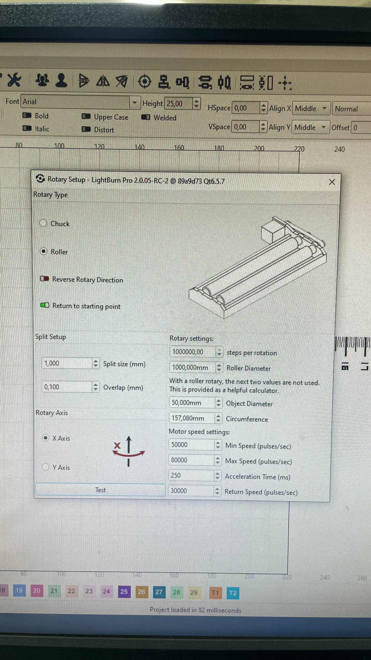
Instead of using 1592mm diam, (5,000mm circumference), with 5,000,000 steps per rotation, use 159.2mm diameter with 500,000 steps, or 15.92mm diam with 50,000 steps - They’ll all do exactly the same thing, and move the same speed.
If the step parameter is set to 500,000 and the diameter is 159.2 mm, the system moves to the 52 cm position (±). After it returns to the zero position, it resumes operation, continuing the marking process on the previously marked section starting from 51 cm onward.
Parameter “eturning to starting position” is turned off.
Video: https://youtu.be/IqvbxleFmYI
In the end of video - params.
This is a bug that has already been fixed, but we’ll need to do another patch release to get it into the 2.0.xx releases.
Regarding the marking, I can’t tell from the video when it’s moving and when it’s not - Do you have a really small split size configured? (that seems like it would waste a lot of time)
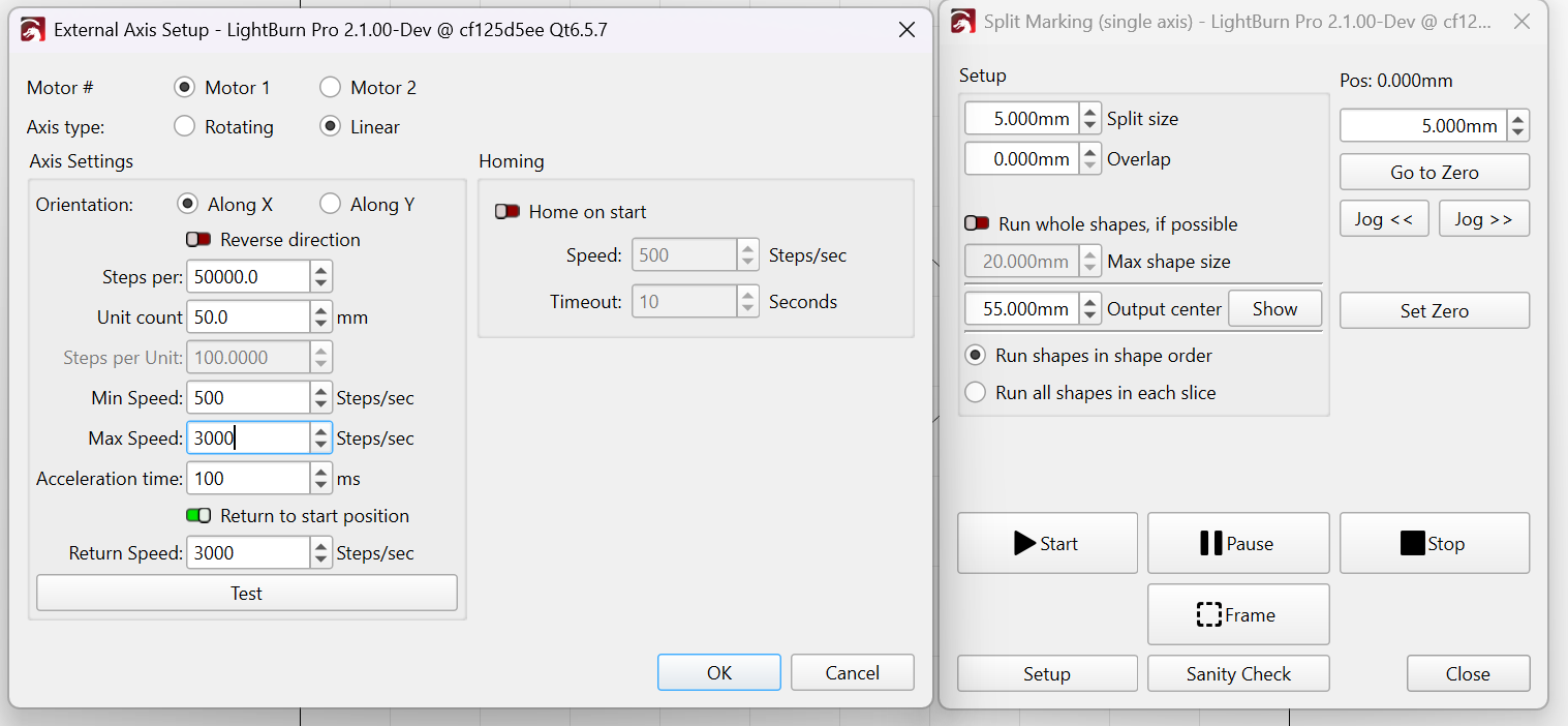
Ultimately you’re trying to hack a thing that isn’t meant to do what you want it to. I have linear split marking almost working, and trying to fix this for you is among the things keeping me from finishing it.
Increase the Split size from 1mm to around 20mm.
You should not need an overlap if your settings are accurate.
This will save a lot of time.
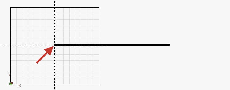
Before using your ruler marks design, try a very wide rectangle.
If both your Galvo Scale and Steps per Rotation are correct, you should end up with no gaps in between.
I’m not sure what this means exactly, but it’s worth noting, that the zero point that you set is here on the workspace:
Currently, we use a workaround with split marking using a preset ruler length of 1 cm with variable text generation from CSV. While this workaround functions to some extent, we need to run 2 steps to mark the entire element (the full project contains both the ruler and marking plate)
Following the last update, we tested the new RC2 version to provide feedback on using rotary mode as linear
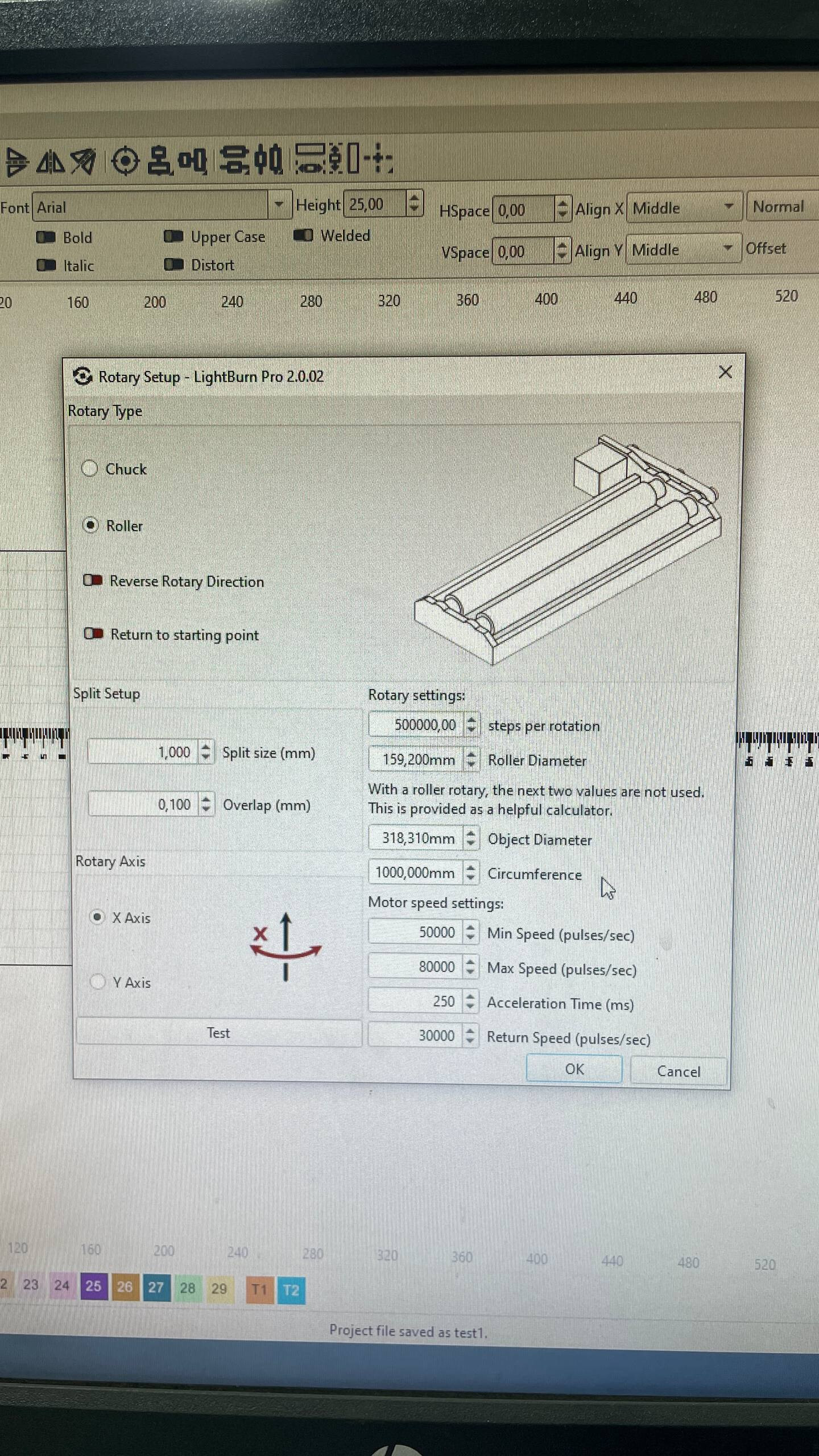
Our Configuration:
Rotary Setup:
Split size = 1 mm
Overlap = 0.1 mm
Working Area Settings:
Type = Roller
Steps per rotation = 500,000
Roller diameter = 159.2 mm
Current Operational Behavior:
We set the zero position at the current 0 mark of the object
Start marking
It begins from position 0 with the 0 mm mark
It continues moving until it reaches the ±52 cm mark (as I understand, this is the maximum range LightBurn allows based on the steps per rotation and diameter value combination)**
After reaching this point, it stops marking and moves back to position 0
Upon reaching position 0, it continues the marking process from where it stopped on the first “rotation” (approximately 52.1 mm)
This cycle repeats until the entire project is completed
Regarding Working Area Size:
Earlier in version 2.0.2, we used a long “table” of 5-meter length, but the problem persisted. So honestly, I’m not sure we need to change WORKING area of laser as its not the same as working area of table? Right?
Ultimately you’re trying to hack a thing that isn’t meant to do what you want it to. I have linear split marking almost working, and trying to fix this for you is among the things keeping me from finishing it.
You’re right, but this is the official approach for handling this type of requirement in EZCAD…
**: The maximum value we can reach is 1 meter (1,000,000 for the steps per rotation parameter).
Increase the Split size from 1mm to around 20mm.
You should not need an overlap if your settings are accurate.
This will save a lot of time.
As for now we dont use current approach (its NOT works) → we just used previous test settings.
I think the easiest way to “hack” this is simply to add an extra zero to the steps per rotation parameter.
A more logical approach, of course, would be to add a new rotation type called “linear.”
Instead of setting the diameter, we would have a “table length” parameter.
It would also be great to have operational “home” switch handling logic (the galvo controller (bjjcz) supports it).
I’m not sure what additional information you need to help you understand the problem we’re facing.