rsx2007
October 2, 2025, 2:33pm
47
Will try test button when will be near laser
I loaded cor file that came with EZCAD software when i added bjjcz device along with all other device settings.
But ok, will try to set correction manually.
But very strange, that while using rotate marking, such problem is NOT exist…
Aaron.F
October 2, 2025, 4:08pm
48
Measure the current state first. → Engrave a square of 100mm and measure. I claim it will come out more like 9.5mm
If your scaling is off, the problem did exist in rotary mode too.
It “worked” in rotary mode because of the small splits of 5mm. The splits moved the linear axis precisely 5mm. But the engraving was still squished due to the wrong scale.
rsx2007
October 6, 2025, 7:24pm
49
Here’s a test of movement with Repeat Marking .
Aaron.F
October 7, 2025, 11:35am
50
That confirms (again) that the Steps per mm are correct. Thank you.
Did you get a chance to measure and adjust the scaling?
rsx2007
October 10, 2025, 8:48pm
51
Have no time and material to test big sizes (sorry), but here some small size info:
10x10:
All looks like almost perfect.
25x25:
Here we already got some shift of approx 0.10-0.15mm
35x35:
Here a bit more - approx 0.25mm
50x50:
and here is approx 0.4mm
Aaron.F
October 11, 2025, 1:28am
52
It’s hard to see, what you’re measuring, if you don’t start with 0.
The difference increases with greater distances.
rsx2007
October 14, 2025, 3:22pm
53
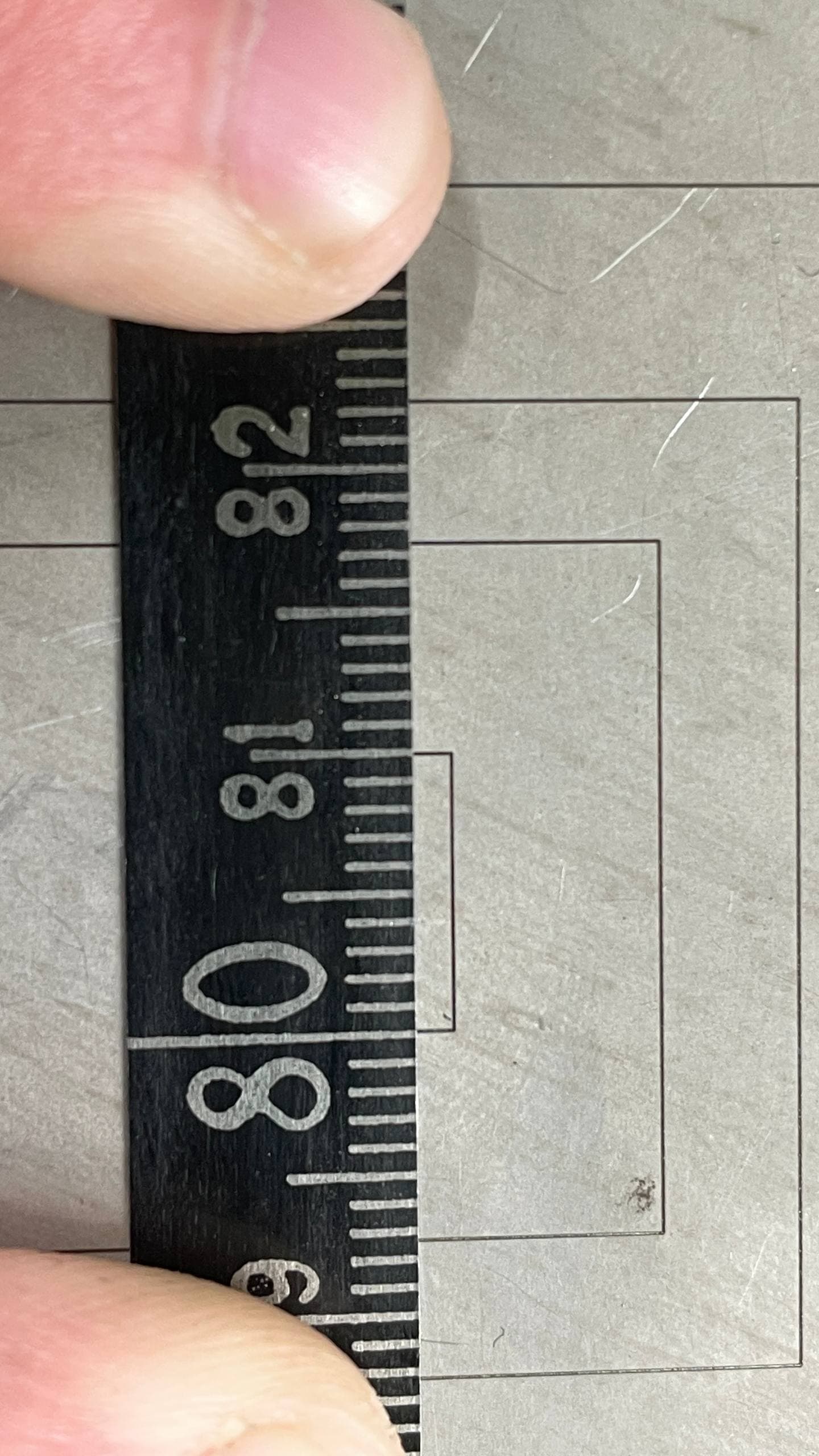
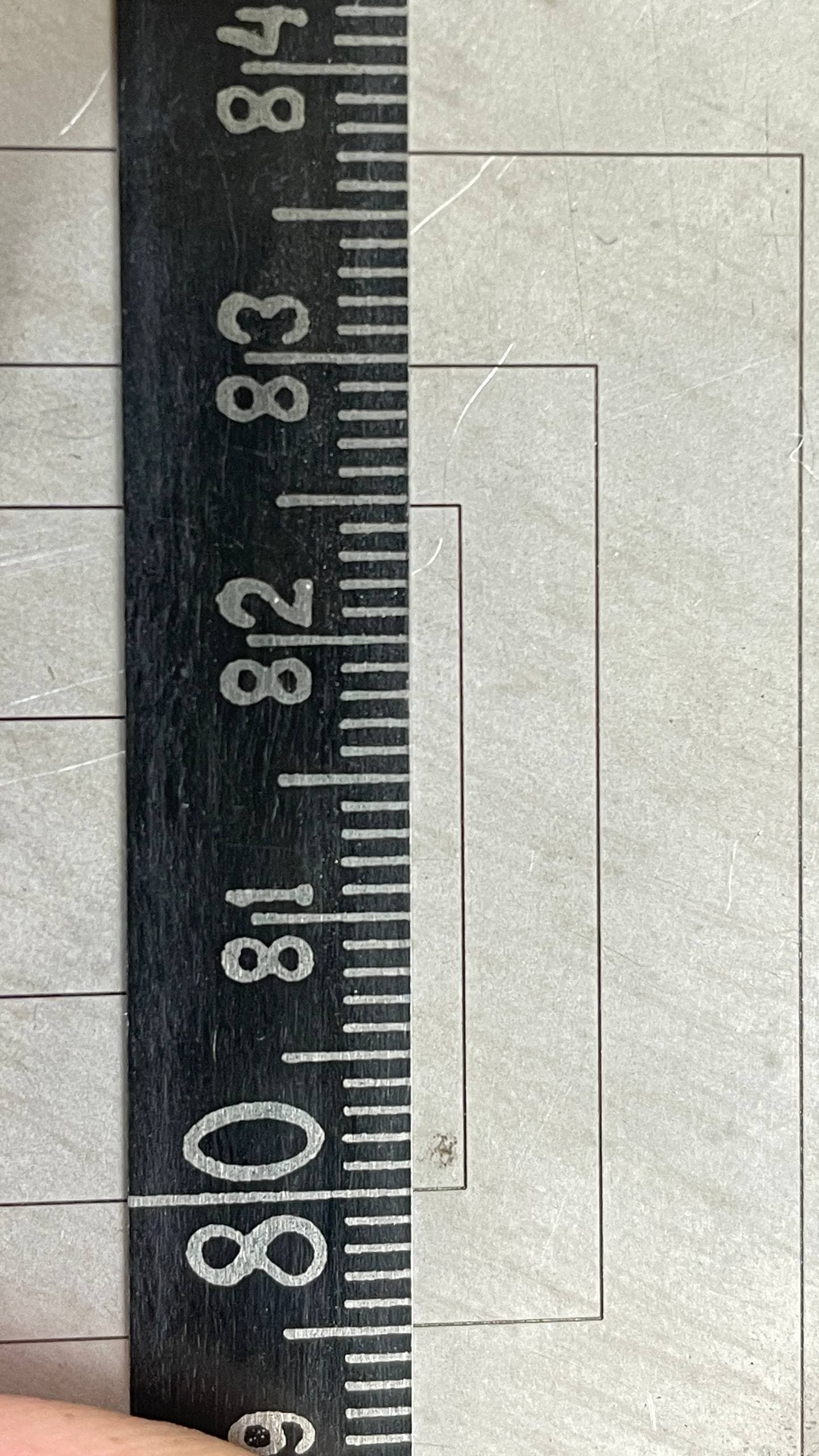
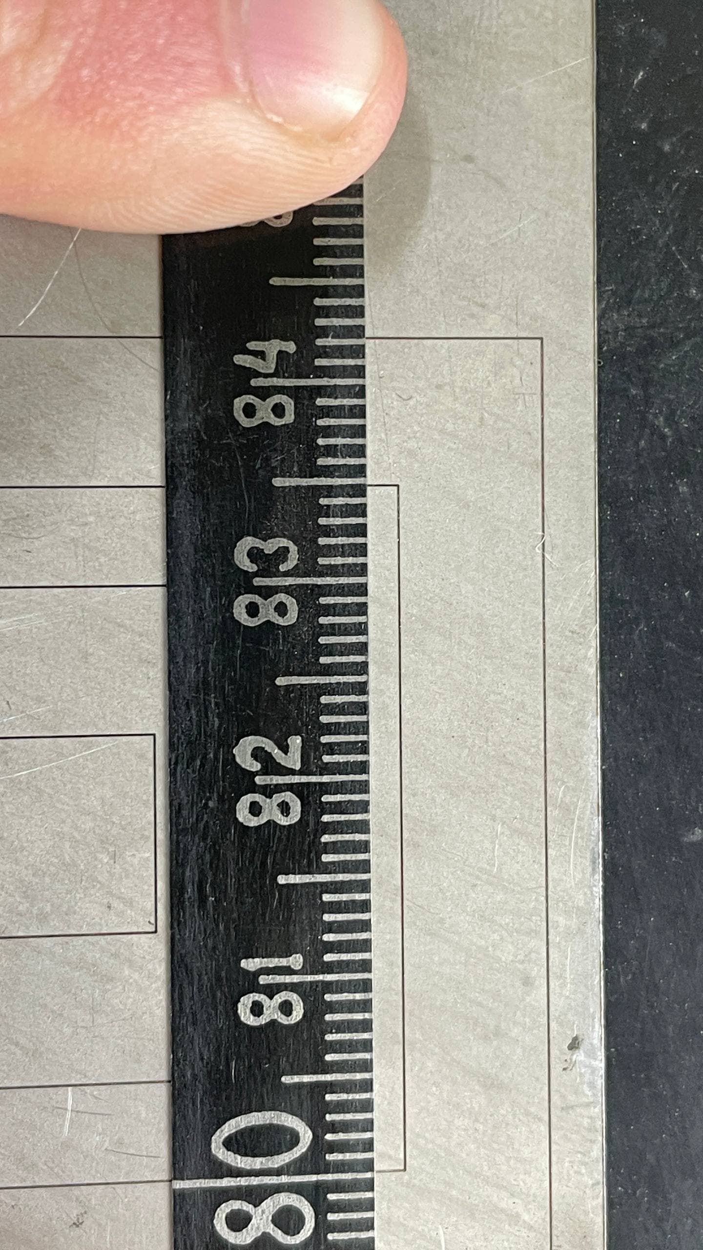
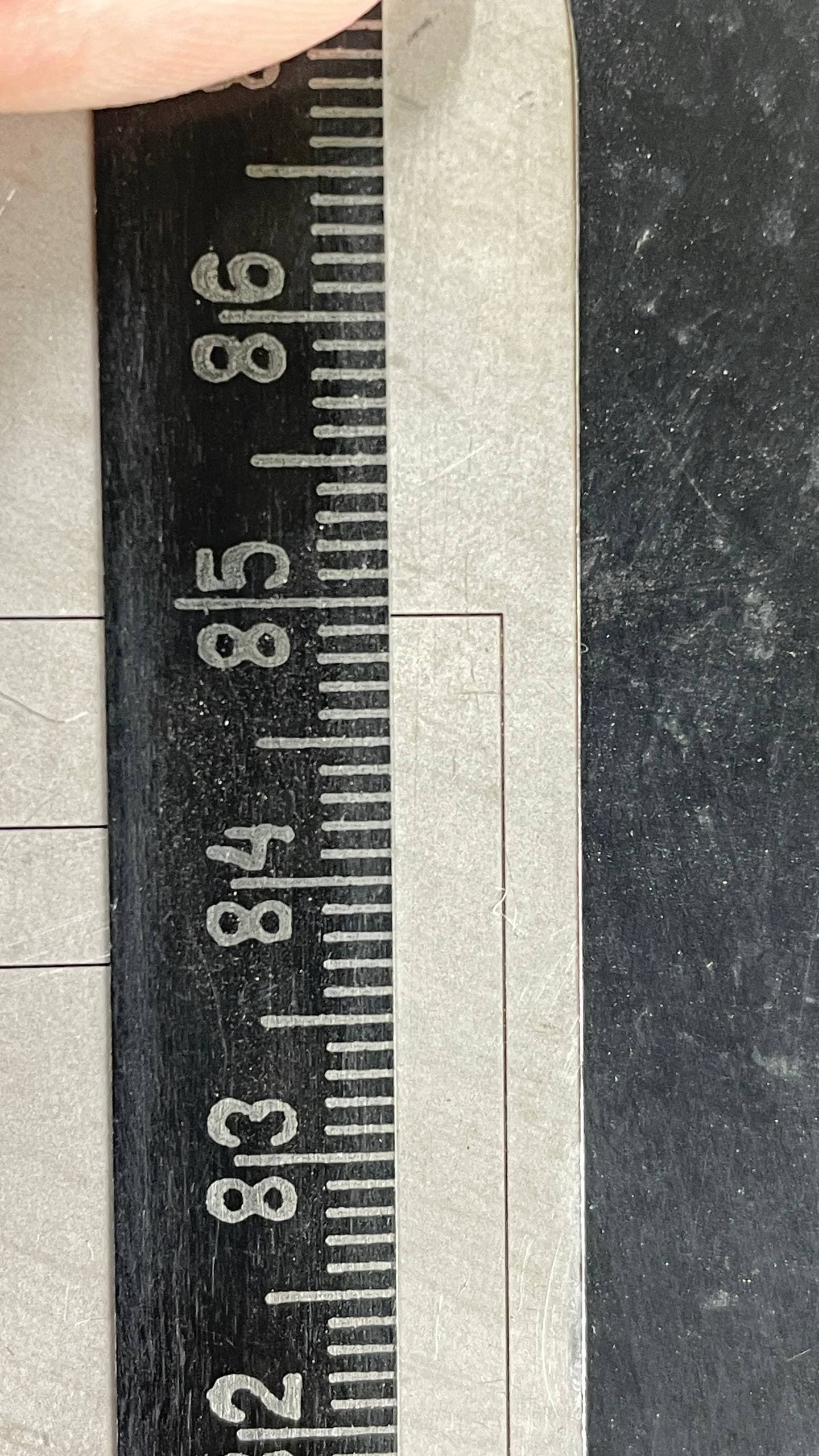
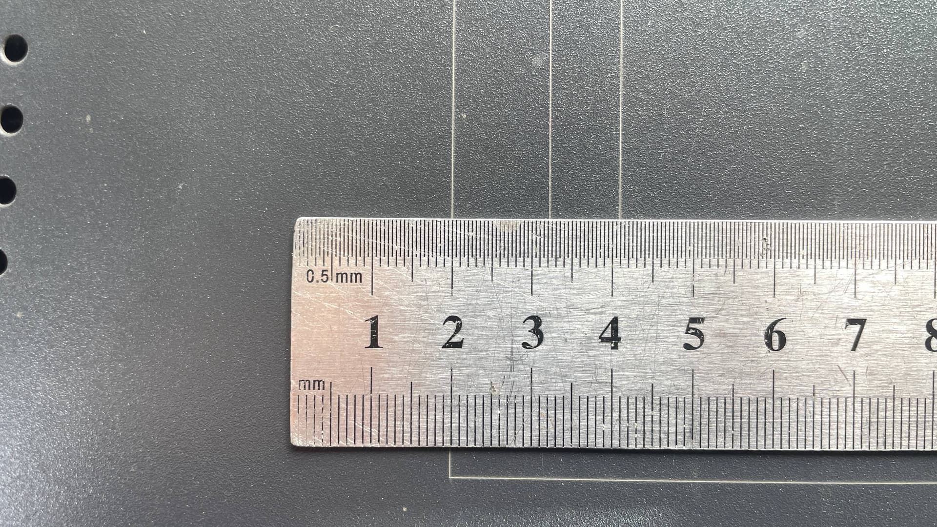
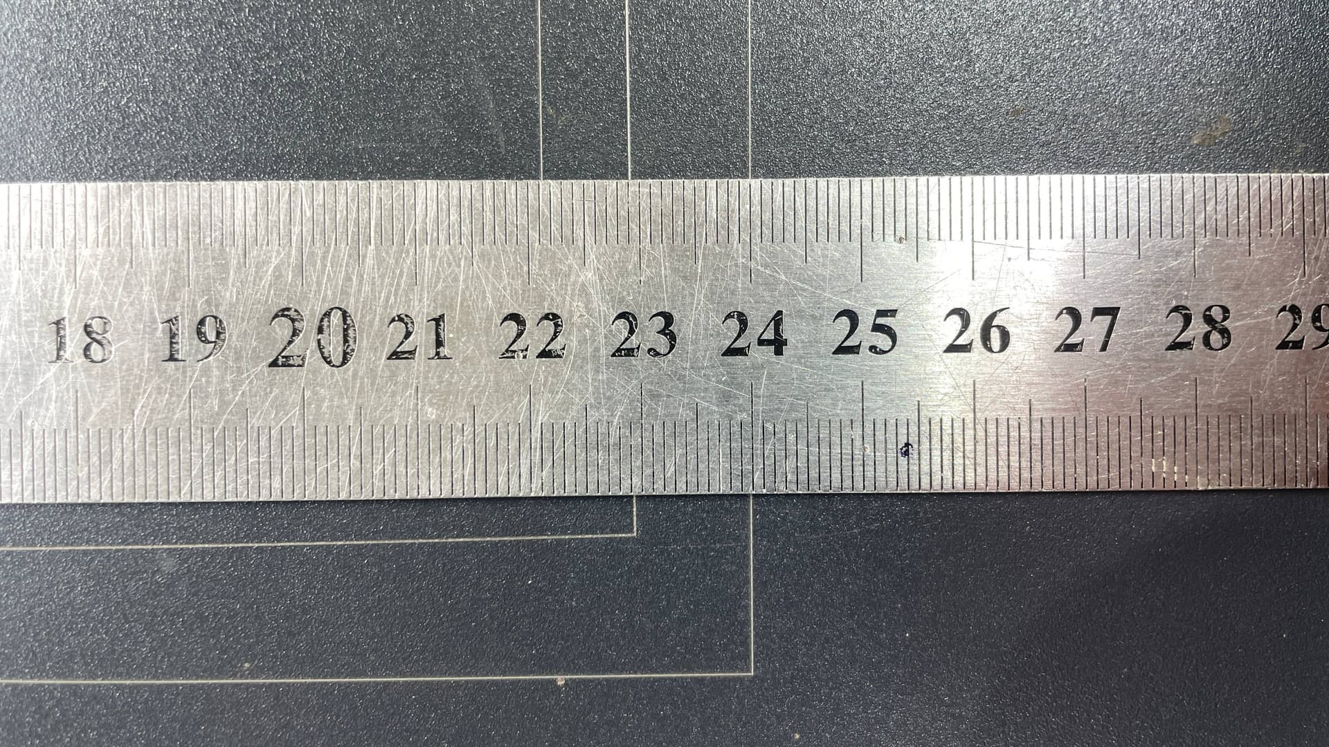
First of all, it’s important to note that the starting point is the 2 cm mark .220 mm .
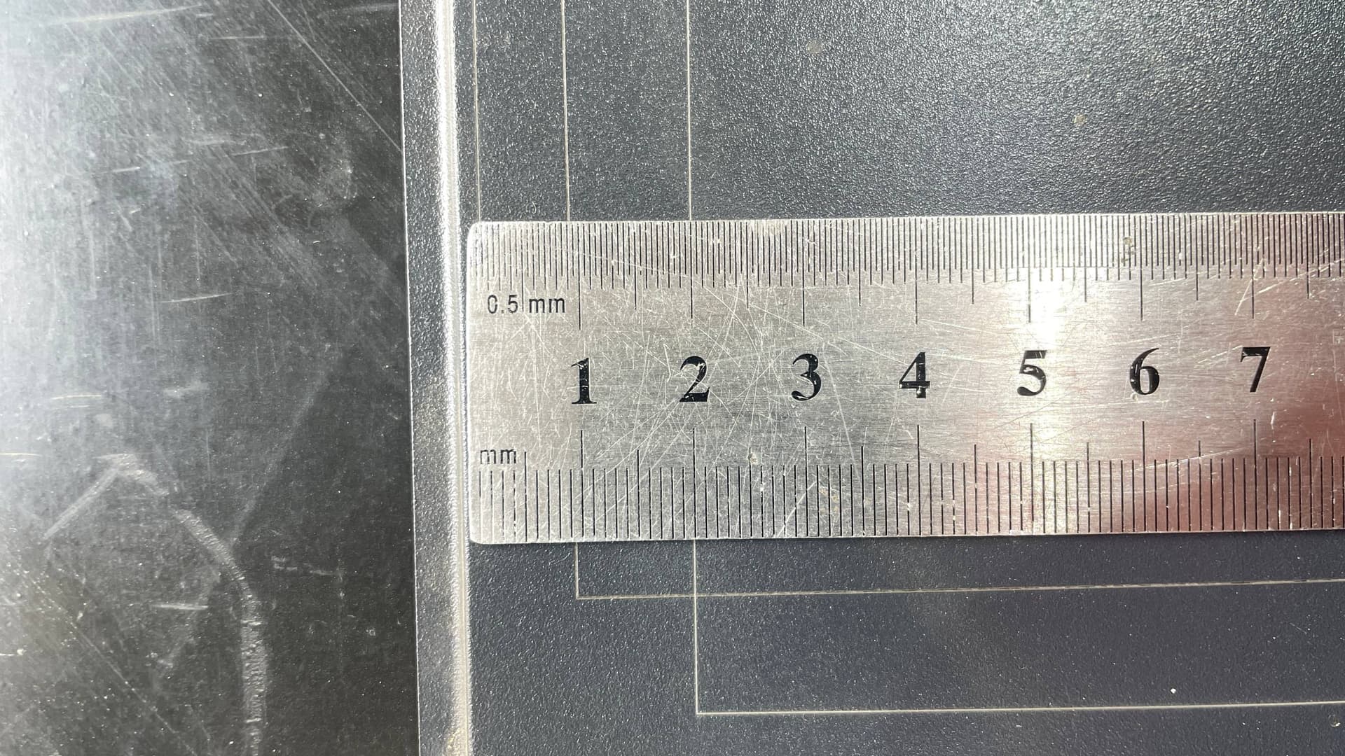
Start:
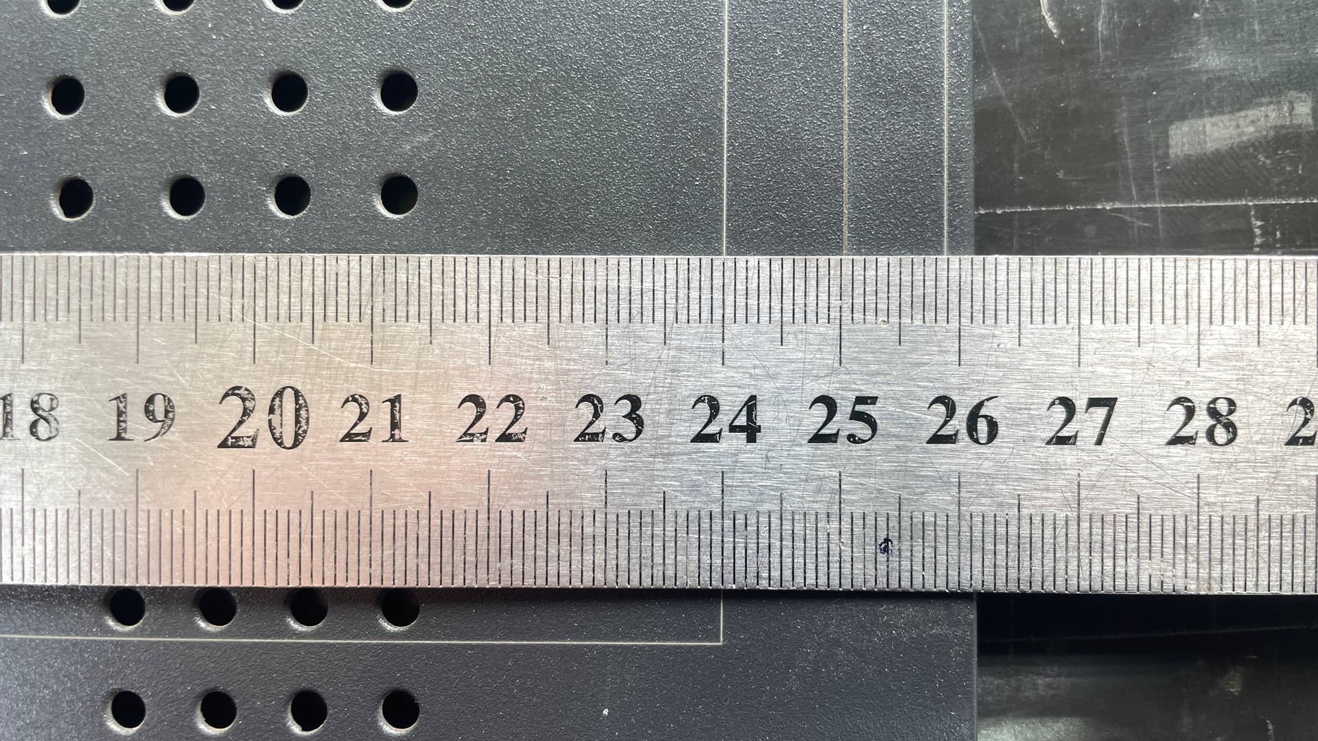
Finish:
Entire area:
Y axis is perfect.
Start:
Finish:
Entire area:
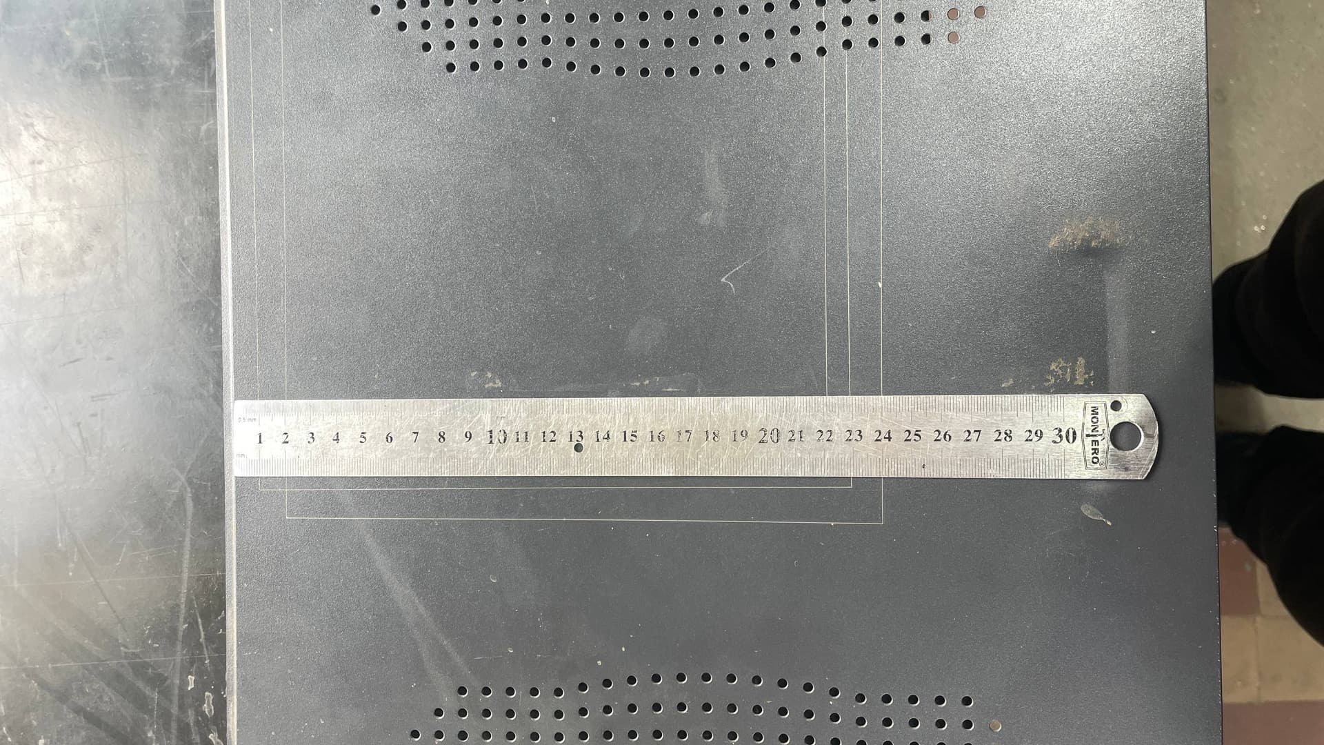
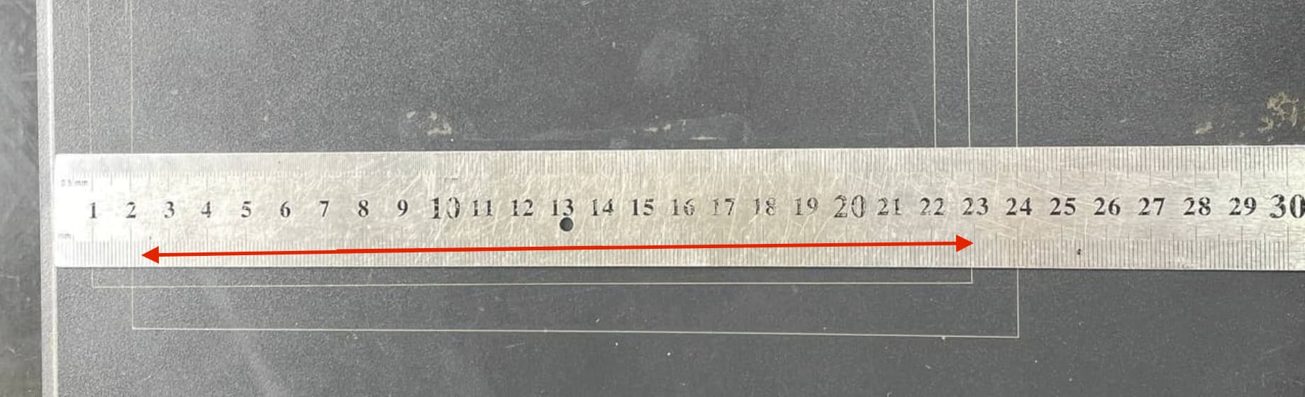
The ruler here is centered, so there’s a small 1 mm difference across this working area (22 cm).
There was also a slight bulge, so I made some adjustments:
However, the result is still not valid — there’s still some issue present:
I don’t understand what could still be wrong…
Aaron.F
October 14, 2025, 3:44pm
54
rsx2007:
Y axis is perfect.
Nice!
rsx2007:
X axis
Did you adjust this by calibrating the Galvo scale in the Device Settings?
rsx2007
October 14, 2025, 4:46pm
55
Yes, and test mark of ruler is the result of marking AFTER calibration.
Aaron.F
October 14, 2025, 7:13pm
56
Was this measured before, or after calibration?
As far as I can tell, it’s almost a millimeter off.
rsx2007
October 14, 2025, 11:42pm
57
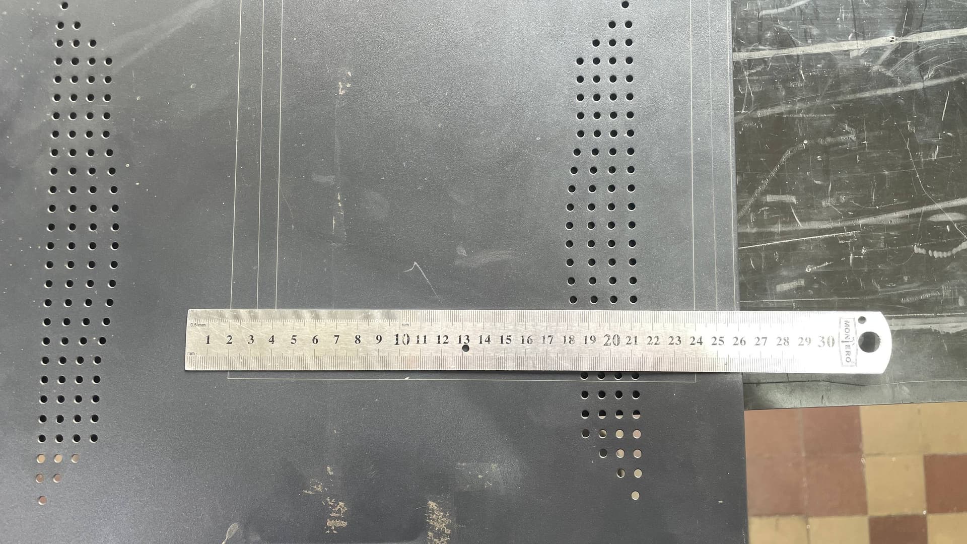
On this image if you treat it from 1 to 23 cm → so yes 1 mm off, i mentioned that earlier:
The ruler here is centered, so there’s a small 1 mm difference across this working area (22 cm).
But 1mm for 230 is pretty much small in comparison with 1 mm per 10 mm (each repeat element) as you can see on ruler.
Aaron.F
November 5, 2025, 3:03pm
58
For your convenience, we increased this limit in the PreRelease candidate of an upcoming version:
Existing Feature Updates
Increased galvo rotary size limits to 20 meters
The second release candidate for LightBurn v2.0.05 is now available to download here:
https://release.lightburnsoftware.com/LightBurn/RC/LightBurn-v2.0.05-RC-2/
Aaron.F
November 5, 2025, 3:08pm
59
It shouldn’t be too long before the aforementioned genuine “Split Marking” is publicly available. This should make setting up a linear table much easier, in contrast to the rotary function, which serves a different purpose.
rsx2007
November 5, 2025, 10:43pm
60
Thank you!
Albroswift
November 6, 2025, 2:03am
61
I see the split for rotary is way over my biggest lens now as well. What is the difference between that and split marking?
rsx2007
November 6, 2025, 2:45pm
62
Well, we tried to test it, but still we are limited to value of “steps per rotation”…
Our motor got 1000 steps per 1 mm, it means for 5 meters we need 5000 * 1000 = 5 000 000.
Aaron.F
November 6, 2025, 6:02pm
63
Split Marking will basically be the same as Rotary Marking, but made specifically for flat linear tables.
Aaron.F
November 6, 2025, 6:17pm
64
I see..
Can you decrease the Microstepping value of the stepper driver? / What’s the current division at?
1000 steps per mm sounds like a whole lot anyway.
Albroswift
November 7, 2025, 2:07am
65
Mine is 320 steps per mm. That still only gives 3.125 meters if there is a 1,000,000 step limit. (which is plenty for an X table but not for your traveler)
Aaron.F
November 7, 2025, 3:10pm
66
You can theoretically set the circumference and the steps per mm 1000 times lower and achieve the same result.