Stroonzo, Why the 4" in it’s normal position and another with a wide nozzle tip down near the nozzle? Some special cutting set up?
what you don’t understand and maybe i can explain
The bottom right is laser at position on table and pulse shot, same for the others.
the mm measurement is the distance between the beams at corners of table.
Mainly for safe Z clearance for situations such as:
- rotary tilting
- engraving objects having things coming up off of them
- engraving without the use of air assist on acrylic without having to worry about lens contamination or caking of acrylic on the nose cone (combined with a sealed machine with aggressive extraction)
- Having more distance from the laser head (lens, mirror, cone) to the objects means less soot build up, less debris on the gantry rail, less debris entering mirror 3 opening to collect on the lens.
Yeah, I was just reviewing the picture again and realized that was the representation. That result (the variation in movement in all directions) is indicative of your beam / mirrors being out of parallel in all directions.
Huh, never thought of doing rotary engraving with a 4" lens. Or is that strictly for the distance?
I have taken to leaving the modified lens holder in as the resident lens because the safe Z clearance for everything is ideal. And with the 60 gallon 3 HP compressor and 30 gallons of auxiliary storage, I have plenty of air and pressure if needed to span the clearance.
where do i start?
Would the tool help?https://american-photonics.myshopify.com/products/k40-reverse-laser-alignment-nut
Where would i start? My table is about 2mm down on right side.
i have tried all sorts of measurements. When beam hits the second mirror there is 2 spots between top left to bottom left.
First is to get your beam aligned, Either the standard way from tube to lens, or with an LED emitter and lens to tube.
Getting your table level to the nozzle is an unrelated physical issue. For me, I pulled everything but the base frame. I picked the high corner, but you could just as easily pick the low corner. Loosen the set screws on the other three jack post gears, and clamp the reference corner in place. I used one of those good squeeze clamps. You just want to prevent it from turning.
Get your reference gap at the clamped post, then move your head to the others and adjust accordingly. Go back and check it once you are done. Some jack post / laser bed configurations may have on side or the other slightly cantilevered. It will put you out a bit the other way if you don’t double check. Once everything is where you want, MARK THE POSTS AND GEARS. Once everything is marked, then go about tightening down your set screws. Inevitably in tightening down a set screw, you will bump, nudge, or just plain move something. Without the marks you will be back to square one. You won’t have a major adjustment, but why go through that when you can just match the marks.
Where can you get the led emitter or would the tool be better to just buy it,
I think there were some links back up the message chain. I’ve never used one. I do it from tube to head so I’ve never needed it. When I have to replace my laser tube, I plan on getting and SPT TR series tube. It has the red dot integrated in the laser output. Red dot and alignment all in one.
Thanks for all the help.
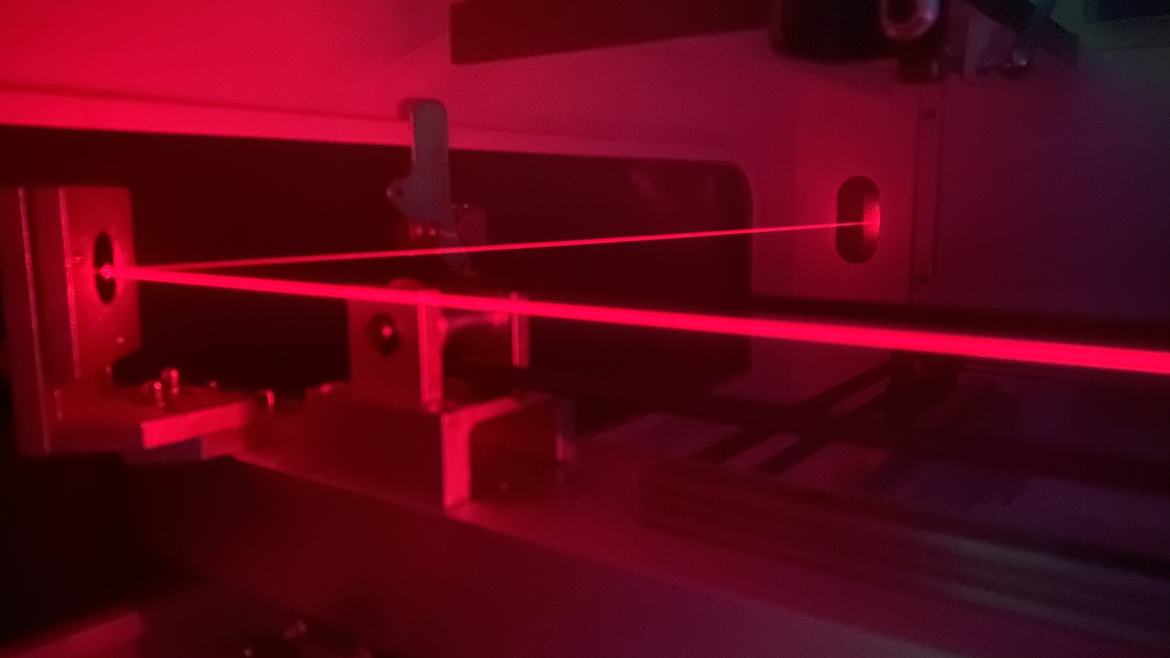
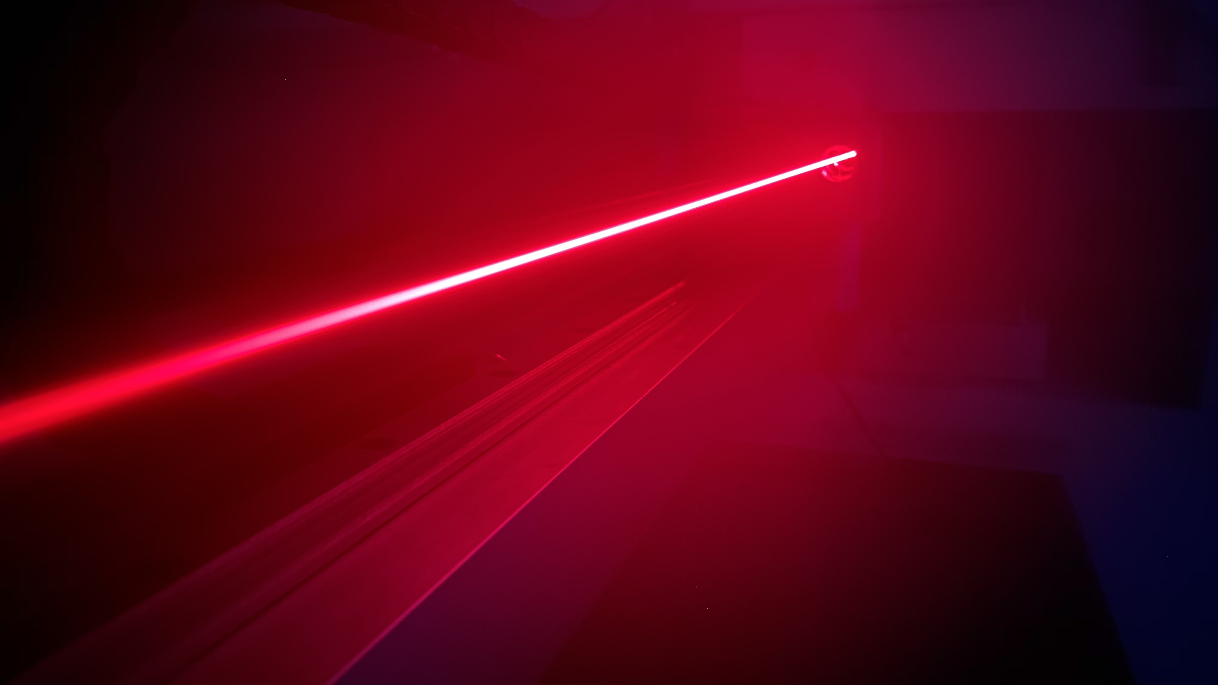
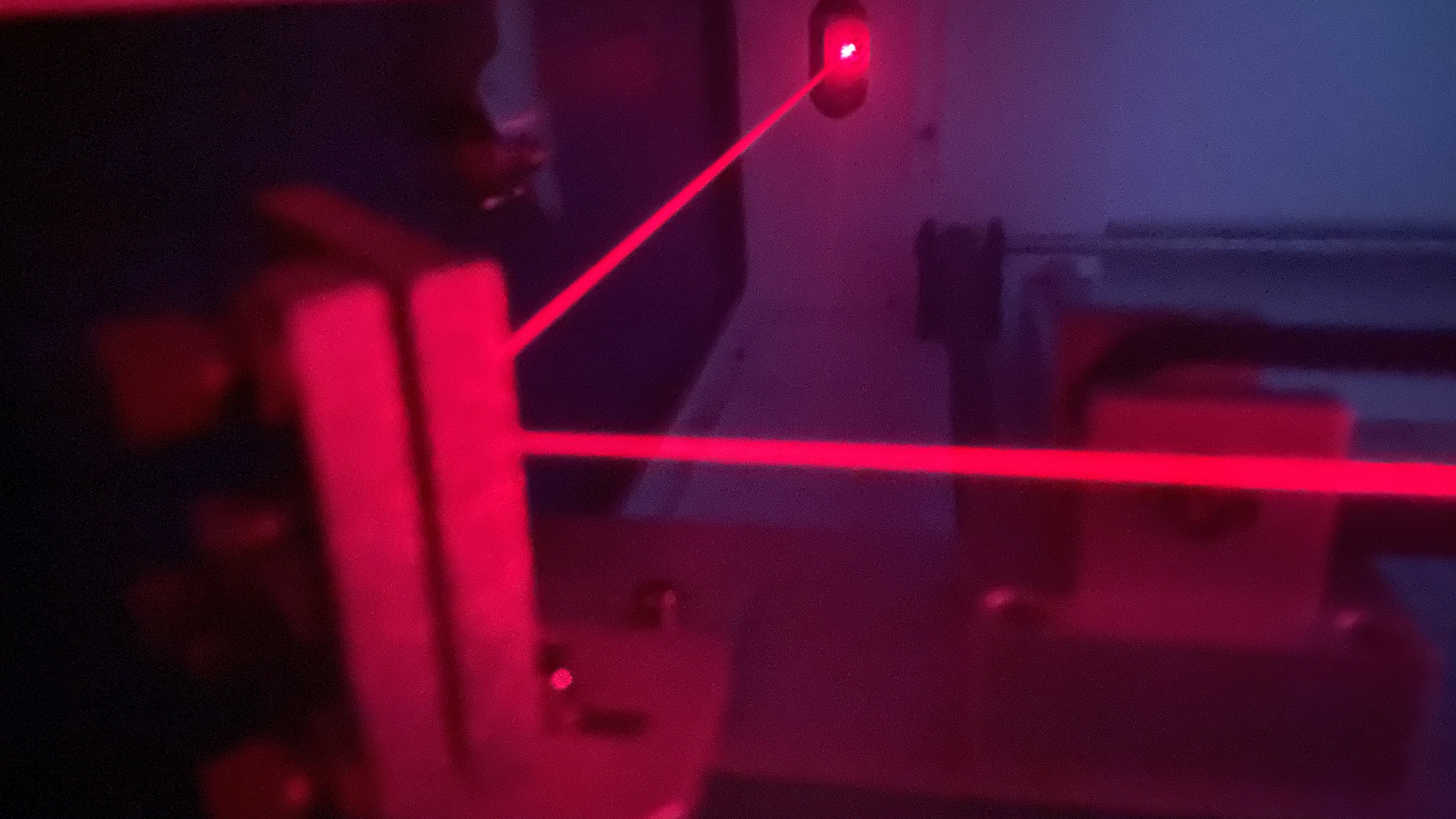
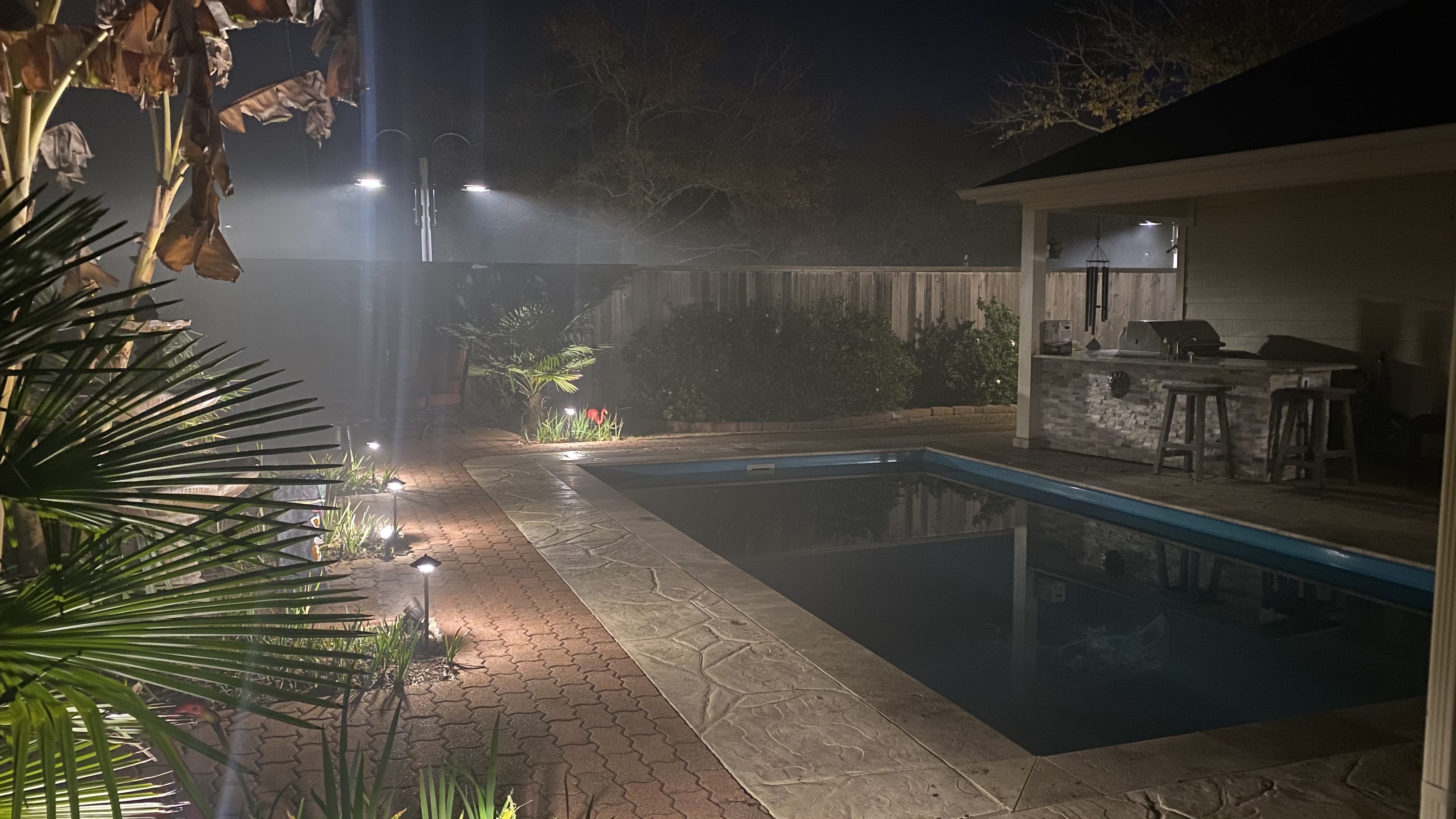
Trust me when I tell you: reverse alignment with some fog in the air is the most superior way to align.
Now I’m going to make it even better and do it with a green laser. They’re much more powerful.
And I made my own smoke juice. 25% glycerin solution in distilled water. (3 parts distilled water to 1 part glycerin).
WARNING!!!
It will be the best and thickest fog you’ve ever experienced EVER.
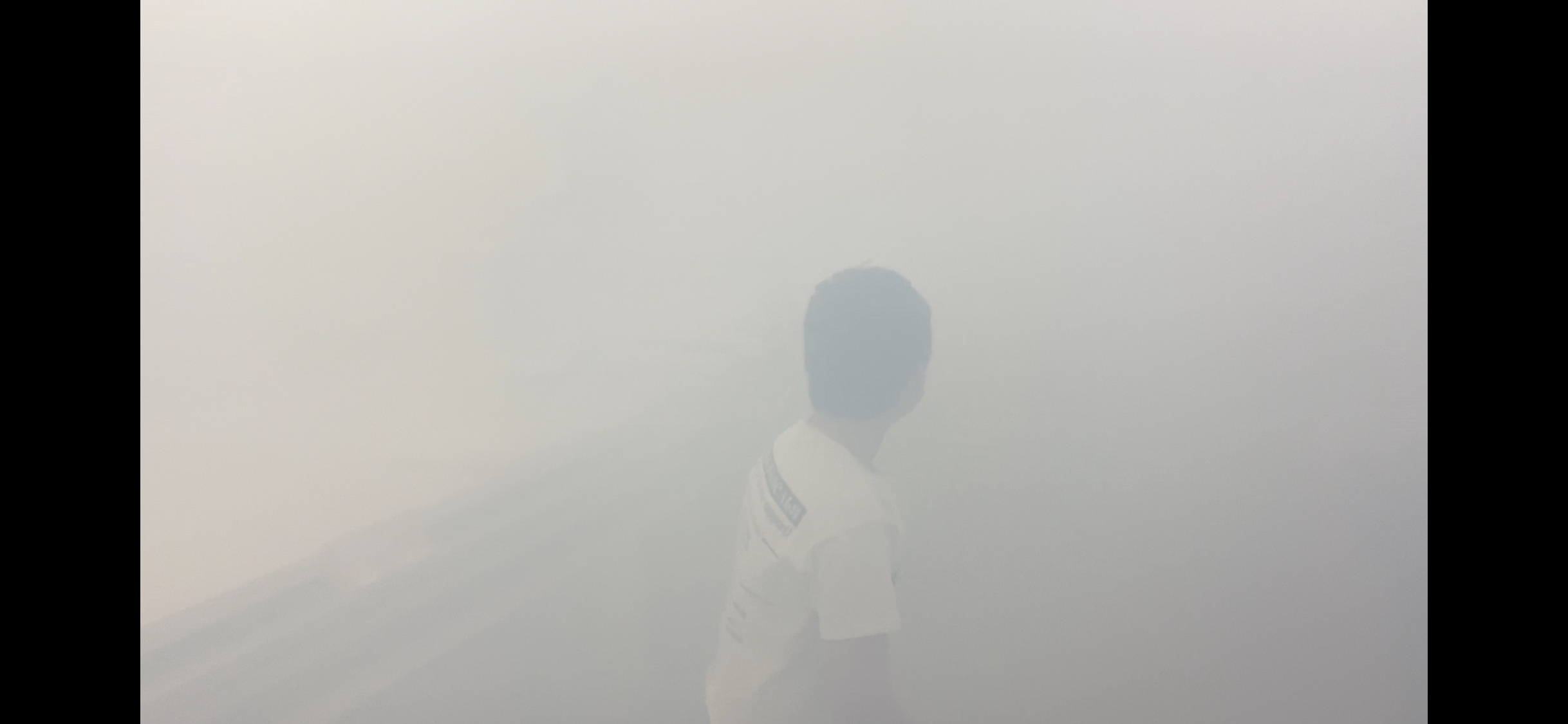
Just look at what happened when I opened the door to the shop, opened the attic stairs, turned on the attic vent, and turned on the fume extractor with the lid open on the machine:
ROTFL
That is quite some fog!
So how did YOU attach your red-soon to be - green laser to the laser head?
Björn,
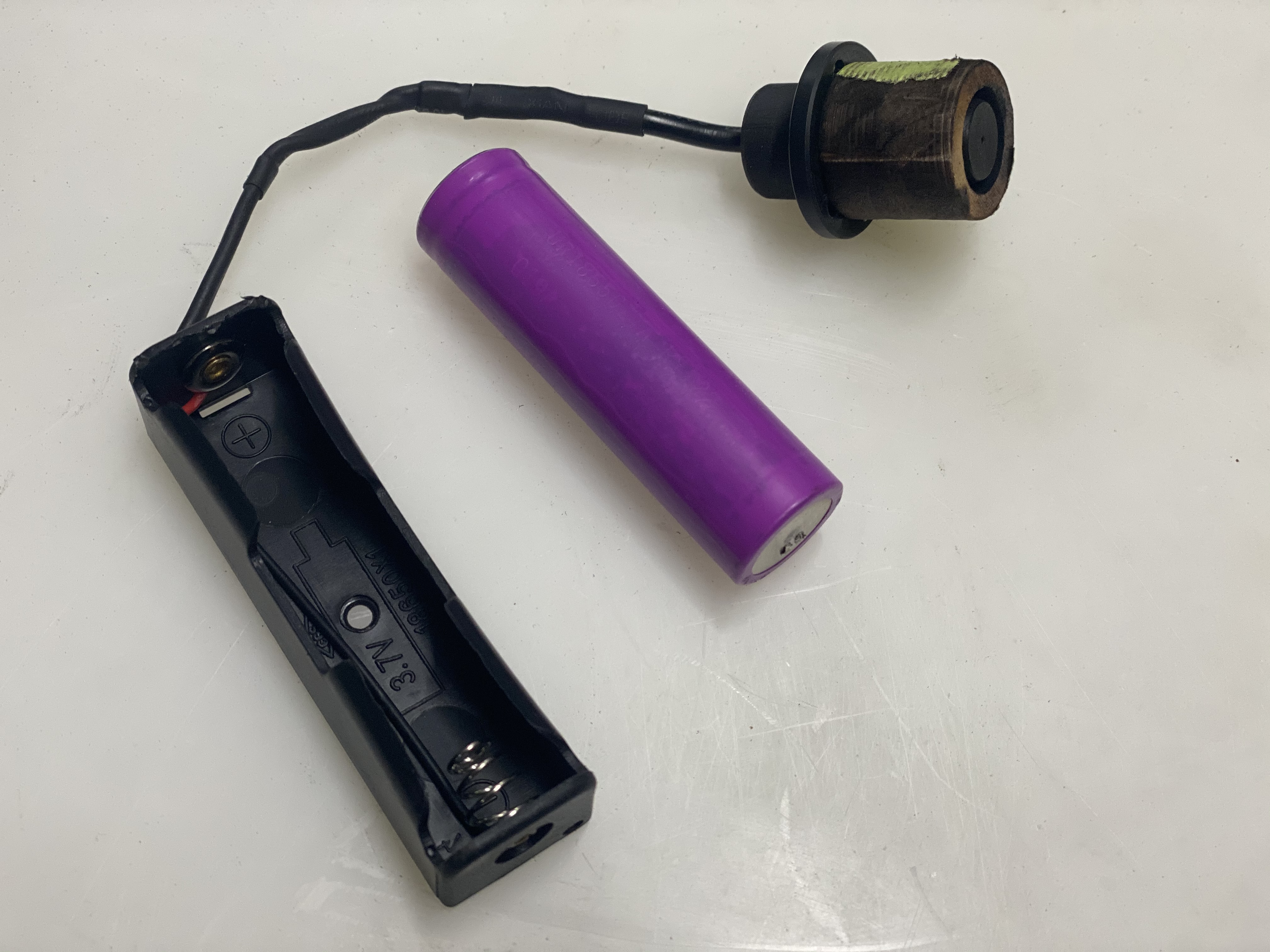
In the above post, you can see that I precisely cut a sleeve from 3/4" (20mm) poplar. The inner diameter accommodates a very snug friction fit of the unused red dot pointer from my machine (that was being stored in a cabinet). The outer diameter (with a little help from tiny strips of painters tape) threads into the lens holder tube as if it were the cone.
To power the laser, I simply soldered on an 18650 battery holder and use a single 18650 Lithium Ion battery. I tested the laser with a bench top power supply and was surprised to find it operated identically from 3V up to 24v (the upper limit of that bench top power supply I was using).
Sorry missed that part of this post.
Awesome fix!
I have a few lasers laying around… sounds like a PLAN for Christmas holiday!
I am surprised this got so verbiage,I have the photonics red dot align tool and I find it very useful, I am waiting for the $25.00 wattage meter to come out…But what I am wondering the most is if their $120.00 (2.5" -63.5 mm) lens is that much better then my cloud ray lens ($30,00)…does anyone have any idea?
I’m perfectly happy with my Cloudray lens’… well all except the one I dropped and broke.
I’m perfectly happy doing my alignment the old fashioned way. And to my way of thinking, You have to do it that way at least once to know that setting it up from the lens end will be truly accurate.I have a B grade EFR QC reject tube that came with my machine. I’ll tough it out until it starts to die and then get the SPT TR series tube. Then it’s no more problem with the integrated Red Dot.
1 Like
I have used the Reverse Laser Alignment Tool and found it far easier to adjust the mirror adjustment screws with the constant-on red laser. In my situation, I had previously adjusted the head using the manufacturer’s instructions therefore I know that the head itself was correctly adjusted. As proof, the Reverse Laser Alignment tool red dot was exactly in the center. From here, I easily adjusted mirror 3 and mirror 2. I found it very easy to adjust those mirrors because I could clearly see the direction in which each adjustment screw moved the red dot by having an “always on” red dot to work with.
The final adjustment, laser tube to mirror 1 had to be made using the machine laser.
In my situation, the machine laser beam was already pointed almost to the center of mirror 1 so I left it alone.