Can somebody please clarify it for me so I can understand I have a series of questions about other controllers such as
I’m asking specifically about a mks dlc 2.1 which I plan on running my k40 mini with. Upgraded 60w power supply 880mm tube
I see many people running a piggy inverter pwm signal do I need this if I’m planning on using that card or do I just plug it up to the power supply to fire the laser on its own?
I see people talking about the cohesion board saying that it can accelerate and take corners of special way
With the board I choose will I be able to connect the laser directly and then drive the laser power with the board and is there a schematic that’s easy for a Layman such as myself to understand cuz I see so many people doing so many things a lot of the piggyback but those discussions seem really old 8 bit stuff times.
I also bought some upgraded controllers DRV8825 assuming since it was microstepping the ultra small detailed pics vetor engrave would have less pixelation?
Since it was 1/32 of a step I figured it could trace a round thing better with smaller steps am I an moron?
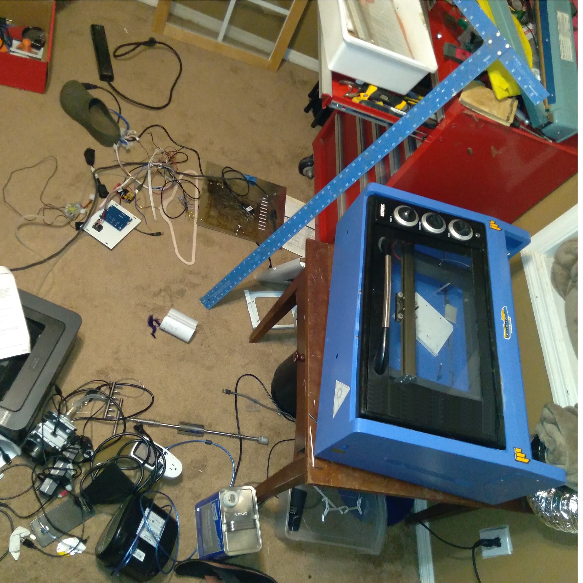
I have a China Blue with a 880mm tube and 60 watt supply. It puts out about 44 watts measured with a Mahoney watt meter.
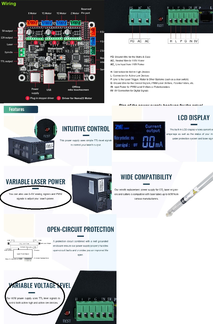
Laser power supplies (lps) turn on and off by the pwm signal. All of the common ones I’ve dealt with turn on when the pwm signal goes high. My little ss laser also follows this standard. The K40 lps has different nomenclature on some of it’s parts.
The board you’re looking at has a ‘laser’ control, but also has ‘TTL Out’ which is generally the pwm signal. I don’t know what the ‘laser’ output itself it.
You would have to ask the people that invert their pwm on the purpose. It appears as if it’s not needed.
Some of these boards have the ability to do some types of configuration as they boot. It’s written to an SD card that the controller reads during it’s boot.
This isn’t my area, but from what I know, when you go to micro stepping, your available torque drops dramatically from that of a ‘full step’ so in the end you could end up with less accuracy. Like everything there is a tradeoff point.
The laser makes a certain size ‘dot’ or mark. Stepping smaller than that by much will not help the end product. Like fine engraving with a Phillips head screw driver, it’s going to make a certain size dent no matter how fine you position it…
The kind of money you wish to dump into your project, it may behove you to check out a dsp controller, like the Ruida. They are not ‘low cost’ like the grbl controllers but do substantially more…
I’ve had a great time ‘hacking’ on mine…you will too, I’m sure…
Take care, keep us up to date on your adventures. Pictures are nice…
Why is there a Ethernet to the power supply? It just seems too simple that i cant believe the board will be able to do it.Seems too good to be true to me.
So If I drop to 1/32 steps I wont have enough torque to slide the laser back and fourth? I still dont get whats gonna happen when I pull 1 chip out and the other will it suddenly start taking 1.32 steps? will I then set my machine to match measurements again? so like it knows 1 inch is 1 turns of hte stepper motor and i have to set taht again? or should it be accurate in its own?
the Ethernet connection on the PSU is to connect an external LCD digital mili Amp meter.
and the power supply does support trigger on High so it should be pretty straight forward from the TTL connection on the DLC board the pin label with an (S) connect to the H connection on the power supply