MKS DLC32 v2.1 connection lost when Co2 Laser Tube fires

Hello guys.
Recently i build a DIY Co2 laser cutter using the MKS DLC32 v2.1 controller.
The Co2 tube is a 40W powered by a black LPSU.

Everything works fine Lightburn talks to the board and gantry moves as expected.
The problem is that when i am trying to cut something after a few seconds i get a disconnection with the following message.

ets Jun 8 2016 00:22:57
rst:0x1 (POWERON_RESET),boot:0x13 (SPI_FAST_FLASH_BOOT)
configsip: 0, SPIWP:0xee
clk_drv:0x00,q_drv:0x00,d_drv:0x00,cs0_drv:0x00,hd_drv:0x00,wp_drv:0x00
mode:DIO, clock div:1
load:0x3fff0018,len:4
load:0x3fff001c,len:1216
ho 0 tail 12 room 4
load:0x40078000,len:10944
load:0x40080400,len:6388
entry 0x400806b4

Sometimes also instead of this message the lightburn shows a busy progressbar which stays there forever.

What i have done so far is:

  1. Changed the USB cable with a better quality. Same think happens.
  2. Esnured that a have a good ground of chassis with the LPSU. Same think again.

The MKS DLC32 is powered by a dedicated 12V power supply.

Connection between MKS DLC32 and LPSU is as the following image depictes.

if i choose to cut something with the LPSU off or set the power to lightburn to 0% it works fine.

Any ideas?

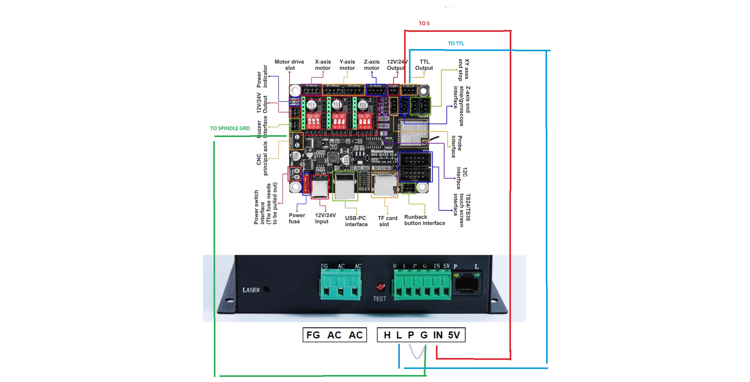
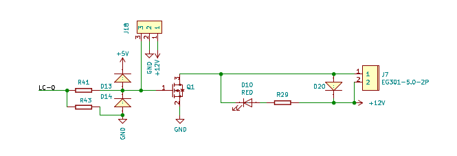
Spindle negative is not ground. J7-1 is labeled as spindle -

If you look at the schematic, it’s switched to ground via Q1 when the pwm goes to a high state.

image

J18-2 is the ground for the led module and the board. I’d suggest this go to the lps G pin, for a signal ground.

On your lps, IN is the current control and L is the laser enable. I’d suggest you wire L through your laser enable switch. This would manually ground it when you want the laser enabled.

Many are wired like this… What you are doing it enabling when the pwm goes high… so there isn’t any advantage to doing this and there may be a disadvantage depending on the pwm period.


This probably isn’t why the controller is failing.

The error message seems to indicate it’s going through a power cycle. Where do you get the 12 or 24V for the DLC32?

:smile_cat:

After further investigation it turned out that there was an EMF (probably) from the LPSU causing the MKS DLC to reset.
I move the LPSU further away to other side of the frame and it looks more promising.
I will test it more thourogly tomorrow.
Any one with same experience?
Any idea how to shield the LPSU or the controller. A faraday cage maybe?

Dear jkwilborn
Thank you for your reply.
With the current connection it seems to work fine but i’ll apppreciate it if you can provide me a small diagram of how it should be correctly connected.

Ground needs to be common for signals to work. J18 is the laser module output, labeled TTL

  1. remove green wire
  2. blue wire to G of the lps J18-2 is ground
  3. Red wire is fine, pwm control J18-1
  4. Console laser enable switch, one side to ground the other to L

You can test this with L strapped to ground. It’s fine for testing, but it’s safer to disable the laser from firing through a console switch.

Make sense?

:smile_cat:

@jkwilborn

I tried as you described and it does not work properly.
As soon as i power on the PSU the tube fires continuously.

If there is no pwm, then there should be no lasing…

Are you sure it’s wired correctly?

There is a different wiring option if you’re sure this isn’t working for you…

:smile_cat:

Please advise.

Some of these wire wiper of a pot to IN. The pot has ground and 5V on each side. This allow you to set the current limit.

They then use the pwm on the H input of the lps, to turn the laser on and off…

Follow?


I’m not wild about this configuration, but lots of people use it.

The wiring I gave you should not allow it to lase. At 0V on the IN terminal, it should not lase, I’d think you have something crossed up.

:smile_cat:

This topic was automatically closed 30 days after the last reply. New replies are no longer allowed.