Hoping to get some help. Just received my Monport K40 Pro yesterday. Got it connected to Lightburn. Turned the knob to max on the machine so that when I test fire it reads 19mA as my max. In Lightburn, my machines $30 is 1000 and my S-Value max is 1000 but I don’t get 19mA when my file calls for 100% power. I can change the S-value max to 9000 to get 8mA but I can’t get any higher.
PWM signal from the board at varied values (S-Value max is 1000)
at 20% I get 1.348vDC (4mA)
at 40% I get 1.708vDC (2mA)
at 60% I get 1.689vDC (3mA)
at 80% I get 2.173vDC (4mA)
at 100% I get 2.704vDC (6mA)
A max S-Value of 9000 only grants me 8mA at 100% power.
Board is receiving a steady 5vDC from the power supply.
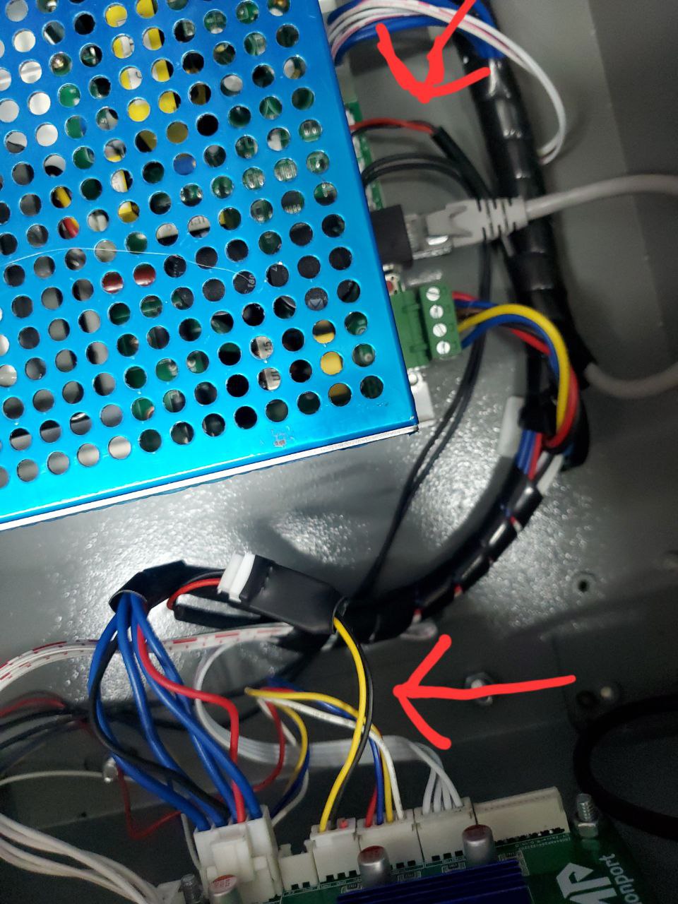
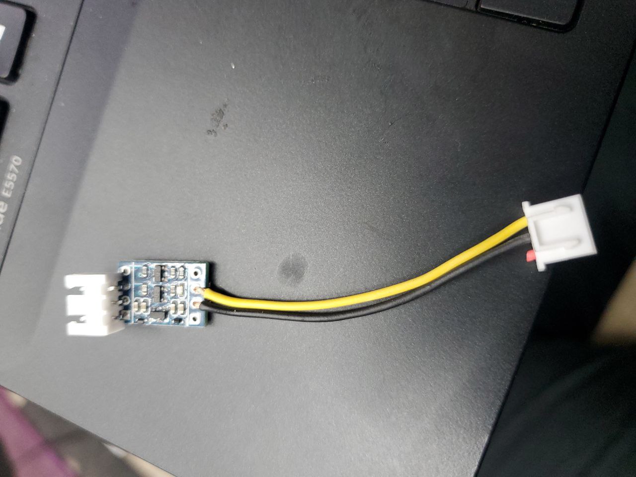
Yellow/Black cable is connected to an unknown board under the heat-shrink before continuing to power supply. Removing this cable does NOT alter my mA readings.
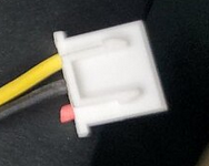
The Black to Ground and Yellow (5v PWM on Board) to Red then to IN on the power supply. Apparently according to other users, the heath-shrink is a booster board by Monport in an attempt to correct this issue.
I may be way off base on this, but I’m thinking about 2 things to try when I get back home.
Possible Driver issue? Driver is currently USB-Serial (that’s all it says)
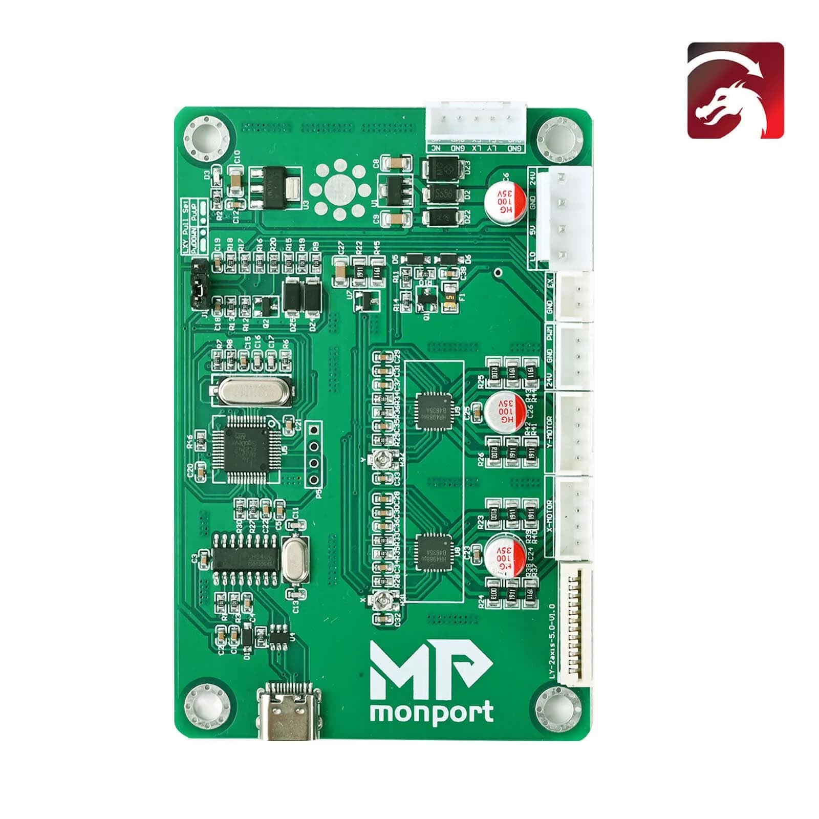
If so, that would put the yellow wire on the PWM pin, correct? Is this where you are testing PWM voltage? If not, test there please. If yes, can you test PWM at the end of the red and black wires after the “booster” board?
Ah bummer. I was hoping it was software related and not a malfunctioning board.
Yes, this is my board. Yes, the yellow is in the PWM pin. I tested at that port without wires connected and again with the booster cable connected. Same results unfortunately.
You tested at the PWM pin with the booster cable connected? Or you tested at the end of the red and black wires beyond the booster board? If the former, then please test the latter scenario.
I’d like to understand how the booster board is affecting the signal.
While not unheard of, these types of issues aren’t generally going to be from a config issue with a fully assembled device from factory. Do you have access to a scope? You could diagnose definitively.
I tested at the PWM pin with no cables connected.
I again tested at the end of the red/black wires with the booster connected.
No changes to the vDC detected. Assumed booster board is not altering the signal in any way.
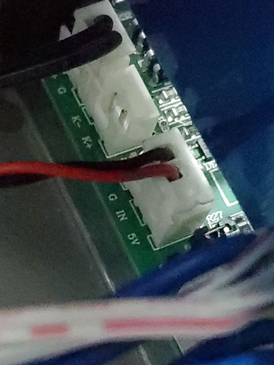
Got it. You may want to try ruling out any power supply issue by passing any 5V signal to the "IN’ pin to confirm that you can get the current output you expect.
If you do that you can isolate the issue to the board.
Can you confirm that the controller is also getting 24V from the power supply? Are you able to jog the machine without issue?
Can you confirm that the controller is also getting 24V from the power supply? Are you able to jog the machine without issue?
I only tested the 5v supply form the power supply. I’ll confirm the 24v line as well when I get home.
The machine jogs and moves as expected at any speed selected 1mm/s - 350mm/s. Executes job files smoothly and power can be adjusted from 3mA-8mA without issue. (8mA only achieved with an S-Value of 9000)
The only reason I can think of why that would be required is if the Monport board is native 3.3V and does not shift voltage for the PWM on the board. That’s a bit unusual for ports made for lasers.
So if true, that would mean you should be getting 3.3V at 100% power at the board which you’re not. So either logic level is not 3.3V or there’s still a hardware issue at play.
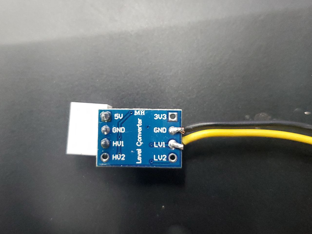
However, I’m not sure if the converter is connected properly. This is a bidirectional converter but wired undirectionally. Not sure if these can work that way. Normally both sides of the conversion need to be powered at their respective logic level voltages.
Let’s ask @ednisley if he’s familiar with these and whether that should work.
Apologies, I see my mistake. I get 3.28vDC at the terminal at 100%
So yea, seems like they screwed this version of the board. Best recourse for them would be to release a new 2.1 version with the correct 5vDC PWM signal direct form the board and ship them out at-cost to current customers.
(no Hijack of discussion) .Timely subject for me , in the middle of upgrading my OLD MLE/K40 ( new belts, Monport LB compatible Green board , digital current meter and inline digital water temp meter, re-designed plate )the water temp meter has been in use but not mounted - just hangs out . I cant add anything to this topic other than to say/ applaud the NO BS concise technical information from the support staff/moderators /techs. Great Job ALL!
JC
Only question then is why the logic shifter is not working to lift the voltage to 5V. The 5V side may need to be powered for that to work but again, I’m not super familiar with these.
But I’d have to think this would be tested before sending out but…
I went ahead and supplied 5V from the power supply to it. The LED on the board turned on. But i realized i have no 3.3v source. Ordered a buck convert and a new Level Converter (just in case) for aditional testing tommorow.