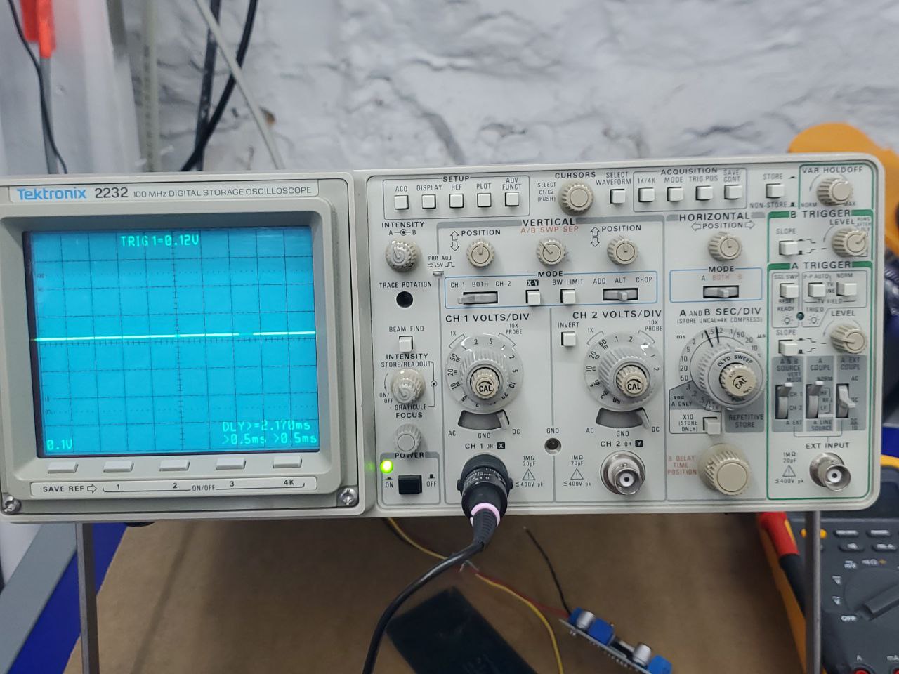
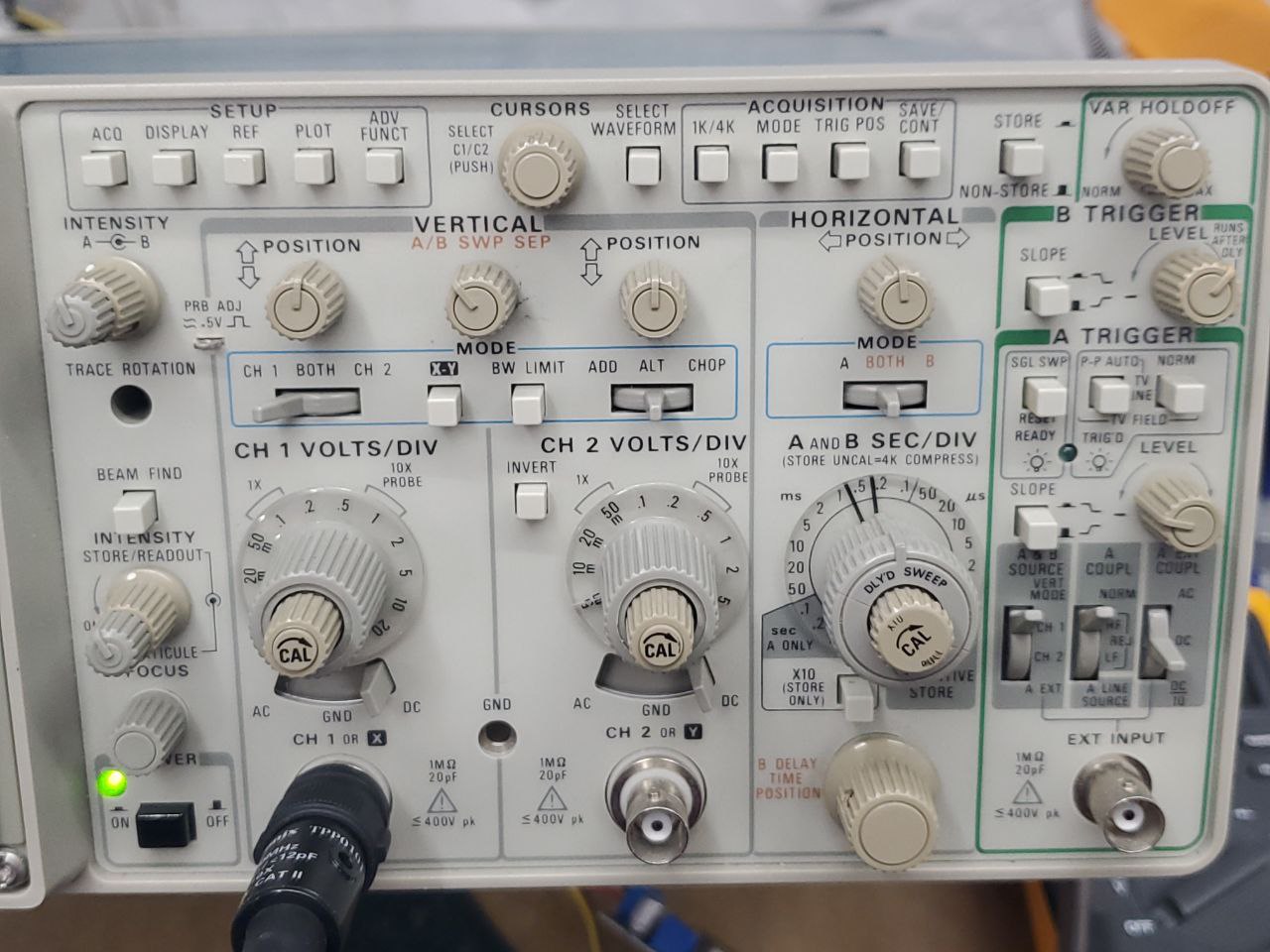
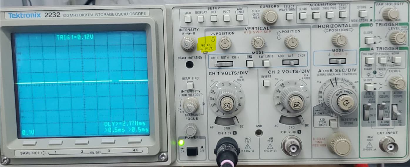
Alright guys, this is what I got to work with. I only know the bare bare minimum. Direct me lol. ![]()
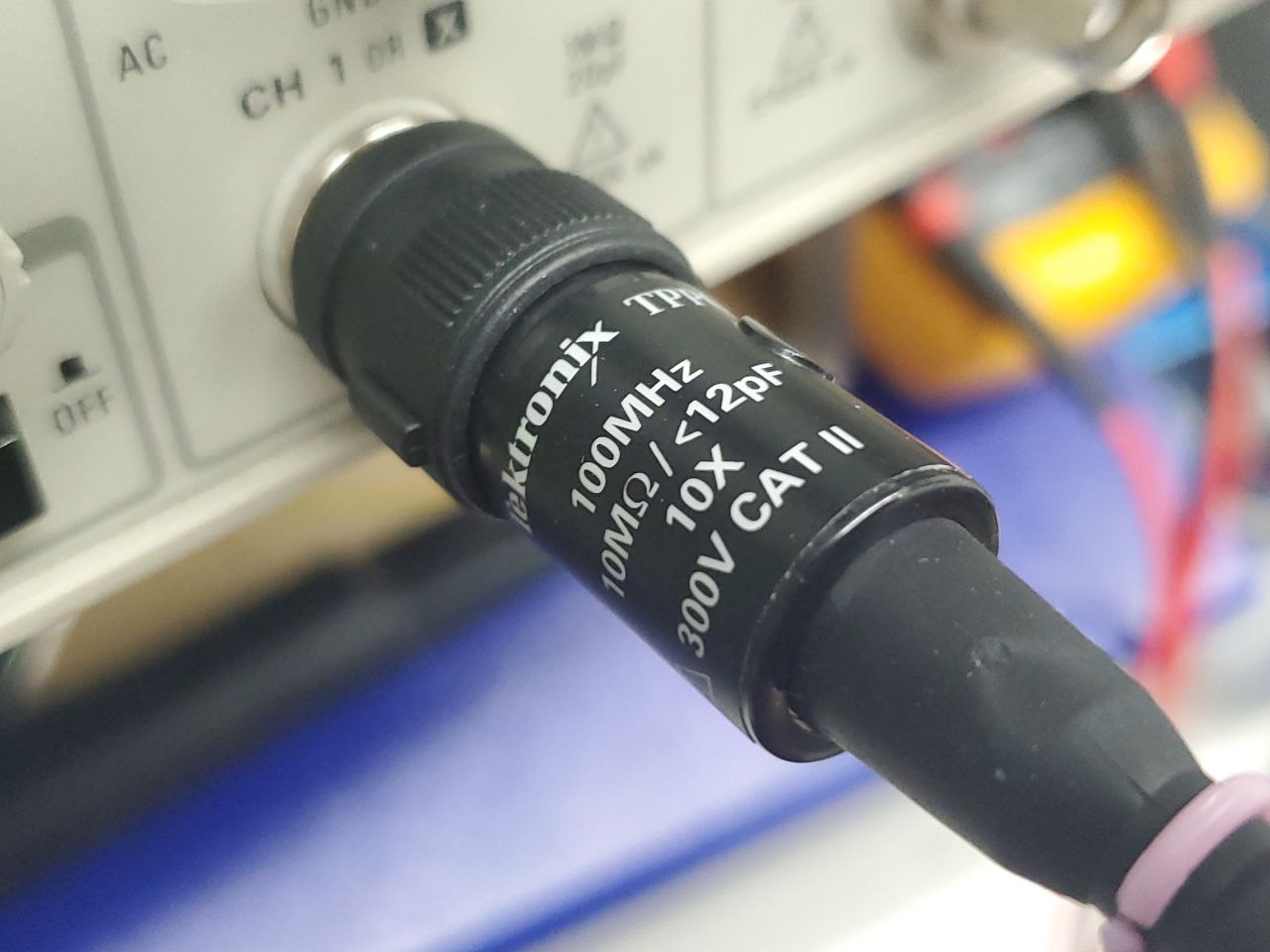
I have 2 of these probs, do not have a 1X prob at all.
Alright guys, this is what I got to work with. I only know the bare bare minimum. Direct me lol. ![]()
I have 2 of these probs, do not have a 1X prob at all.
It’s always a possibility… Again I’m making assumtions.
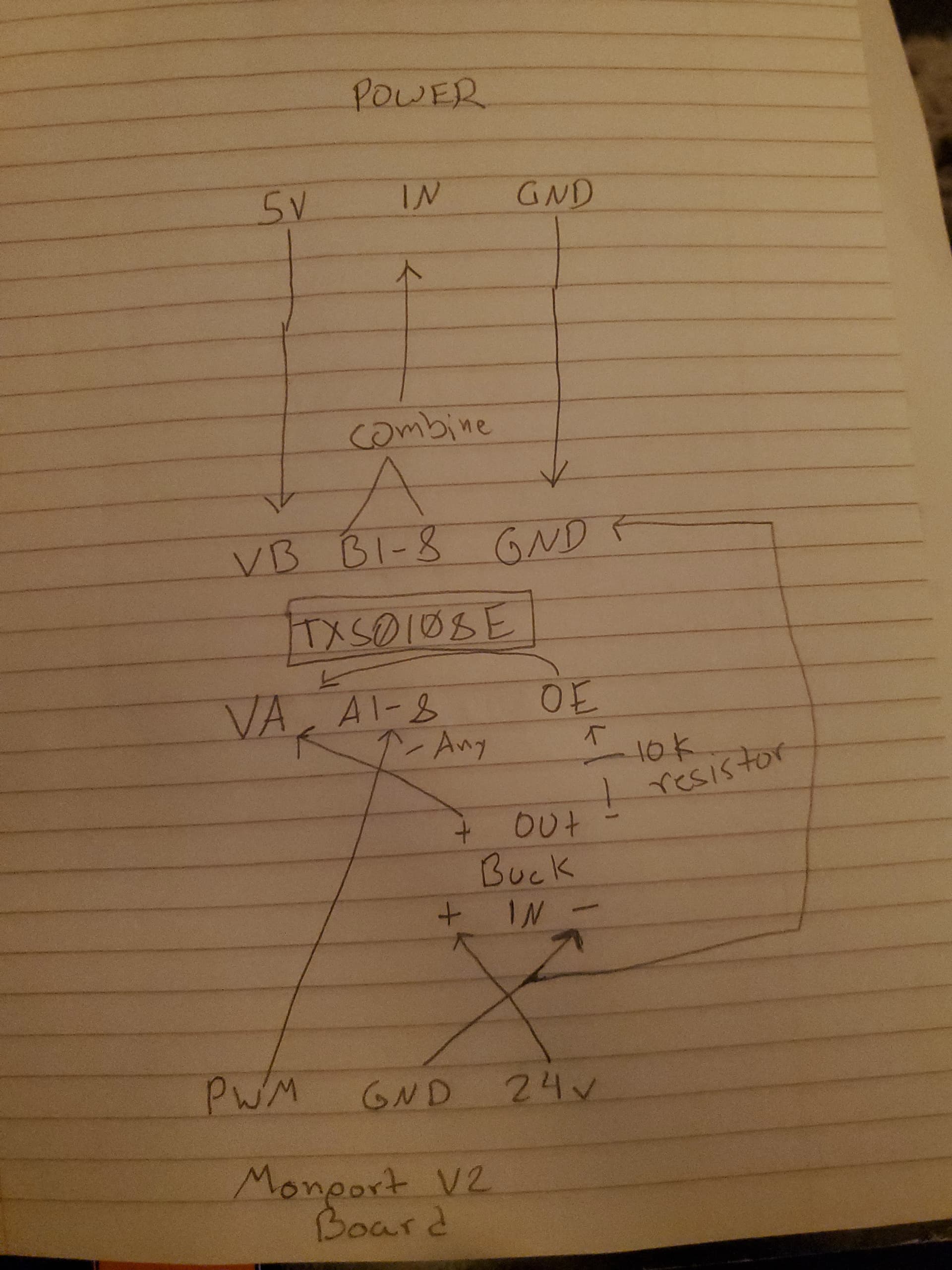
To get this fixed, I think, we need to assume it’s a 3.3V controller → level translator-> lps.
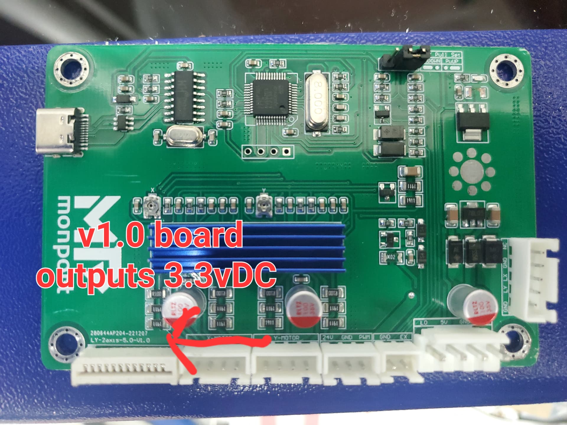
I don’t know what PWM 3.3V means in this context … 100% power should also be a constant 3.3V.
If these are correct, it’s got to be the translator or lps.
I mentioned L because I don’t know how it’s implemented here.
Too bad Monport won’t gives us the pinout or a rough schematic. The installation video is plug and play type instructions.
This is the most I’ve seen on it.
Most of these have the pot control wired to IN and the pwm goes to L or H…
![]()
That’s been the working assumption. Only leaving doors open as to not have blinders on.
OP is saying that if he applies a known 3.3V to the low side of the converter that he gets 5V on the high side. However, if he applies what’s currently assumed to be a 3.3V PWM signal at 100% duty cycle that he reads 2.84V on the high side.
I see the converter as a potential problem but why the LPS? He’s measuring this before the LPS is in play. As-in on the high side of the level converter.
Note also that using the test button on the remote yields the expected current from the LPS. OP also tested a known direct 5V onto IN of LPS and got the same expected current output. I don’t think the LPS is the most likely culprit at this point.
Given they went through the trouble of a custom PCB it’s seems surprisingly poorly documented and I find it funny that they needed an immediate level converter add-on fix. Clearly something got missed.
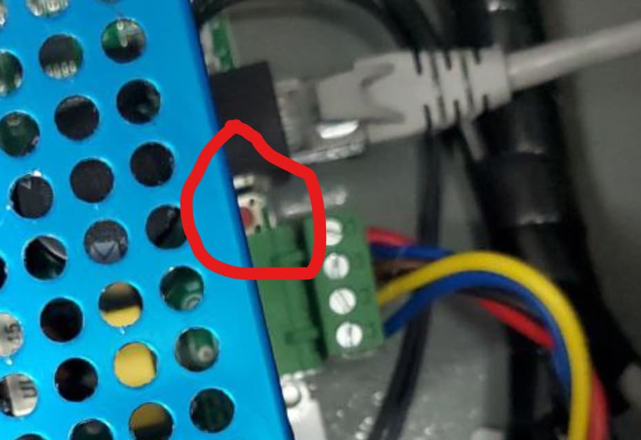
OP’s is not using that. He has a digital remote control that plugs into the RJ-45 connector on the LPS.
Based on the analysis done by another user the RJ-45 connector has pins that are bridged to G, IN, L, and P+. So it attenuates overall power and can also run a test fire operation.
The issue seems to come up to the interface between the translator and the lps.
Been burnt by assuming A is failing and in acuality it’s B…
Signal → A → B
With these connections it’s applying a control voltage to the IN terminal. There is no other reason to have an IN connection.
The question becomes what happens when you have the control voltage and a pwm signal on the same pin?
Thanks for the RJ-45 pinout. I was suspicious that it was the same ol stuff…
Some of these have a switch on them next to the RJ-45, do you know if his has this?
![]()
The first time I saw this was recently with another K40 type. Didn’t realize these could work that way.
Do you mean on the LPS itself?
It appears so:
Thanks for all your help over these few days.
Monport has a board issue that they need to resolve and provide for free to customers that have this issue, of which I assume is everyone with thier K40 Pro w/ V2 Control Board.
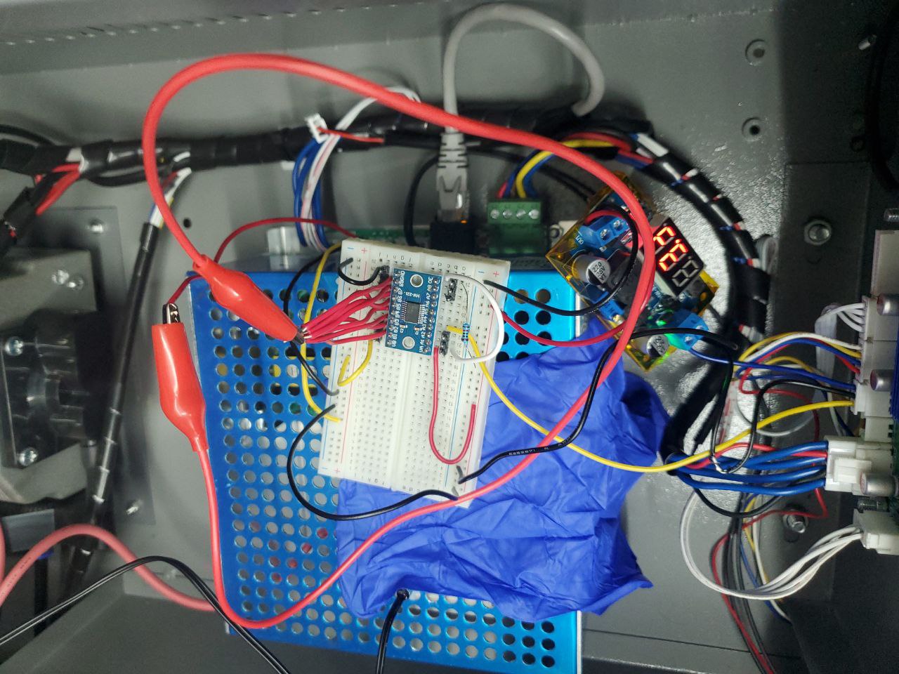
For now, I fixed it for myself. Im going to try to document the montrosity we came up with for the next guy.
V2 Board is supplying 3.3vDC PWM and this TXS0108E is translaying it to 4.49vDC on the power supply IN port which gives me 11mA, after that I dialed the knob on the laser up a bit more to get 14mA. I can get a total of 16mA using this method but not the max of 19mA i get with the test fire button.
14mA I think is a good place to stay for longevity.
Lowest I get is 5mA when requesting 10% in Lightburn.
Good to hear it’s working acceptably.
So to confirm, both the original logic converter board and the second converter board were not working correctly? Looks like you have a third board that you’re now using?
That is indeed correct. The TXS0108E, and only by combining all 5v translation pins.
That definitely sounds sketchy. Each channel should function independently as to allow for varying signals to use the same convertor board. But hard to argue with results.
Was thinking the same. But, for some reason, all pins activate and only some pins at 4.9vDC and others at 2.85vDC so I said ef-it and combined them. We’ll see how long this lasts. Only need to last as long as it takes Monport to come up with a proper fix, or I just go ahead and switch boards.
The weird thing is, with all 3 boards, we saw the same result. A 3.3v signal from the board only translated to about 2.85v instead of 5v. No idea whats going on there. The TXS0108E having 8 ports that for some reason all activated is the only things that helped.
Interesting. Hopefully someone who knows these boards better can explain what’s going on.
Actually seen a sliding switch to disable the panel control… some have said just removing it will work…
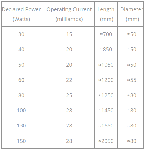
I wonder how it’s working anyway… Suggest current be limited to about 15mA as 100% current…
![]()
I’ve been wondering this since first seeing IN being used for both pwm and laser activation.
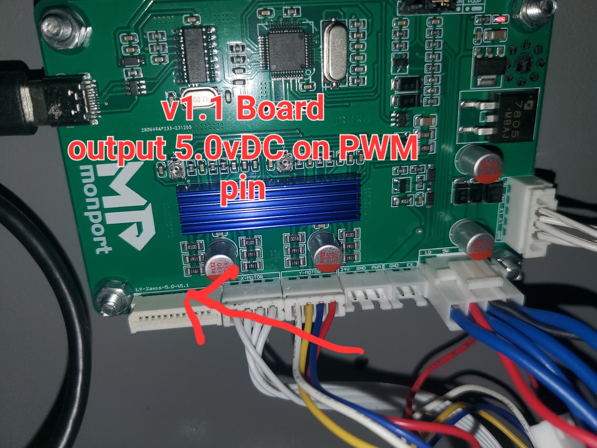
Just received my new Monport v2 board I had ordered (at the same time as this Monport K40 Pro) for my old Omtech K40. It is revision 1.1 and outputs a 5PWM signal.
So, true solution, order a new board. Though, they should still be shipping these out to customers.
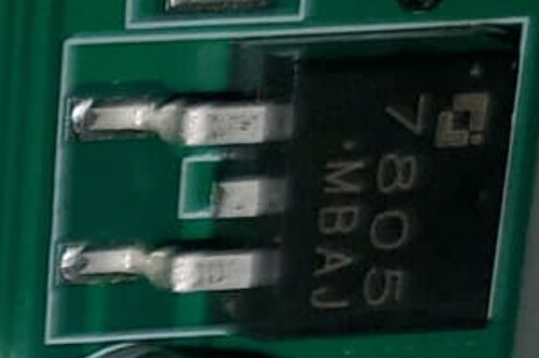
Looks like they added a voltage regulator to provide 5V.
Note that I don’t think there’s anything fundamentally wrong electronically with using a voltage converter even if it’s to solve a bug in V1 design. However, it should obviously be the right part, wired correctly to solve the problem, and actually solve the problem. Still a bit surprised that nobody bothered to even check if the fix worked.
They could have just wised up and run the controller at 5V… ?
I have a couple 328p processors that I run at 3.3V… a bit slower, but still plenty fast.
![]()
Reading over the datasheet it doesn’t look like the MCU is able to run at 5V. Max recommended supply voltage is 3.3V although it does have some 5V tolerant inputs. From what I can see outputs are limited to supply voltage. So they’d have to adjust voltage on one side or the other at least.
Atmega328p can operate from 2.7V to 5V (some sources show as low as 1.8V) so more flexible in that regard.
I didn’t spend any time reading over the data sheet, so I’ll take your word for it…
Seems odd they’d produce and sell a board that doesn’t work, but it’s appearing as if they did.
I’m wondering if there is an issue with the IN pin being used with two driving sources… sounds like a bad idea to me…
![]()