Request: High-density XY correction map for calibrating galvanometer lenses—more than 9/25 points
Hello, LightBurn team,
I’d like to suggest a calibration feature that I believe could solve a problem many users of precision galvanometer lenses face, especially when using larger lenses or those with longer focal lengths.
I know that a 25-point calibration has been requested several times, and I’ve also seen Colin mention that a 25-point calibration is in development, since the 9-point calibration is sometimes insufficient for long lenses.
However, I’d like to suggest something slightly different than simply increasing the number of points.
The Problem
The galvanoscope lens can be calibrated geometrically very well using the existing 9-point correction, although the local scale is still not uniform across the entire field.
For example, a 200×200 mm field can be calibrated so that the outer dimensions are correct, but a 10 mm feature might measure:
-
10.00 mm near the edge
-
10.4 mm somewhere between the edge and the center
-
11.00 mm near the center
-
and then return to the correct value toward the opposite edge
This is particularly problematic for:
-
rulers and scales
-
precision measurement marks
-
templates
-
printed circuit board etching
-
arrays of small parts
-
mechanical parts with precise dimensions
-
any application where a 10-mm element must actually be 10 mm regardless of where it is located in the field
There is already a very similar discussion on the LightBurn forum, where users describe scaling changes in the galvanoscope field despite lens geometry correction:
It is important to note that this is not simply a matter of the “Scale,” “Curvature,” “Skew,” or “Keystone” settings. These settings cannot account for arbitrary local scale changes within the field of view.
There is a very simple way to solve this problem
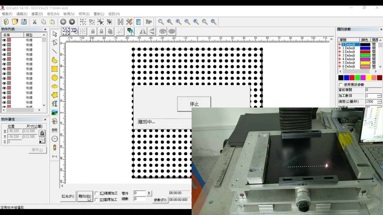
EZCAD2 has a relatively little-known feature accessible from the calibration page using the Ctrl+E key combination in the F3 menu.
It allows the user to create a dense calibration grid and specify an offset correction along the X/Y axes for each point.
For example, a 21×21 grid contains 441 points:
●──●──●──●──●── ... ──●

│ │ │ │ │ │

●──●──●──●──●── ... ──●

│ │ │ │ │ │

●──●──●──●──●── ... ──●

│ │ │ │ │ │

...

●──●──●──●──●── ... ──●
Each point has only:
ΔX

ΔY
For example, if the desired coordinate is X=25.00 mm, but the optical system actually places the mark at X=25.50 mm, then the correction for this point will be:
ΔX = -0.50 mm
There is no need to create any new complex optical models.
Conceptually, the existing LightBurn workflow can simply be supplemented with one additional step
Current concept:
User coordinates

↓

Lens correction / COR

↓

Galvo command
Proposed concept:
User coordinate

↓

Search for local ΔX / ΔY values in the correction grid

↓

Add interpolated correction

↓

Existing lens correction / COR

↓

Galvo command
In other words, the existing 9-point calibration / COR will not be replaced.
It will continue to perform global geometric correction.
The new correction map will simply compensate for residual nonlinear / local distortions.
For any given coordinate, LightBurn will find the neighboring grid points and interpolate their ΔX/ΔY values.
This can be implemented as a calibration grid that the user can edit, for example:
-
5×5
-
9×9
-
17×17
-
21×21
-
25×25
-
etc.
It is not necessary to limit yourself to exactly 25 points.
Why I Think This Is Especially Useful for LightBurn
The user doesn’t necessarily need to understand the math.
LightBurn could provide a calibration template, allow the user to measure the actual positions, and then automatically calculate the necessary ΔX/ΔY offsets.
Better yet, an experienced user could have the option to manually edit or import a correction map.
This approach is already used conceptually in other electro-engraving software and controllers. EZCAD3 employs a similar multi-point approach, and industrial controllers, such as BSL/JCZ-based systems, also provide multi-point correction.
There are also real-world examples of users employing 17×17 (289-point) correction maps with other electro-engraving software, as 9 points are simply insufficient for certain lenses.
For example, this recent discussion on the LightBurn forum mentions 17×17 multi-point correction and the fact that even 5×5 correction files still cannot be properly utilized by LightBurn at this time:
Below, I’ll share a video demonstrating how to use this in EZCAD2 or other controllers if I can find one:
Ezcad2 (I only found promotional videos on youtube for the calibration software, but these are the only references to the Ezcad functionality described above):
“watch?v=BMYxHhlZeMc”
“watch?v=wrYFkPA0RL0”
I also found a discussion of this issue and this solution on Reddit:
“/r/Laserengraving/comments/1tbm79g/ezcad2_corfileexe_calibration_dead_end/”
I hope something like this will be possible in Lightburn someday?