Hi everyone, I am building a laser cutter using skr v1.3 (fw smoothie) and controlled by lightburn.
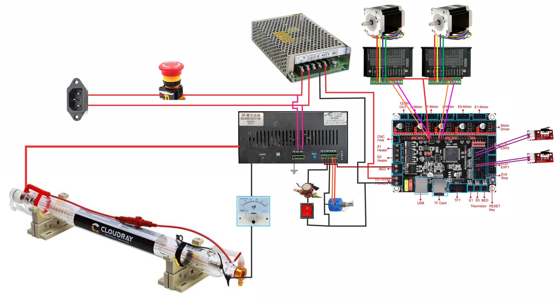
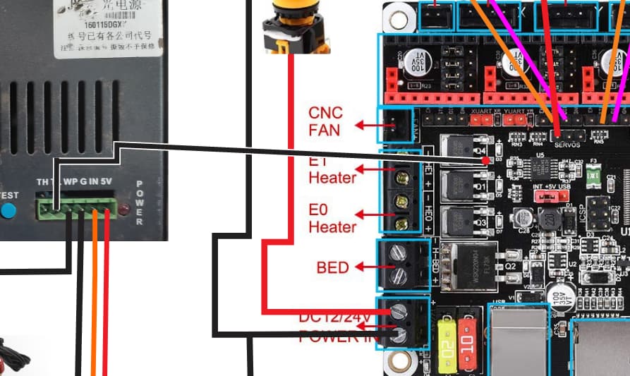
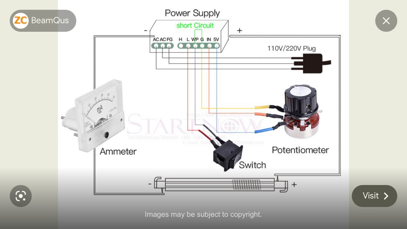
I have wired as attached photo.
Engine X, Y worked as expected. I haven’t connected the power supply and laser tube yet because of safety concerns.
I draw my connection plan as in the photo, hope everyone considers if I have the right connection?
Thanks everyone!
I’m not familiar with that controller but the connectors are labeled like it’s a 3d printer controller. The concern that I see is to connect bed signal to the high pin on the power supply. Bed is normally designed for high current 12v or higher. HI shouldn’t exceed 5v. That signal has to be switched 0-5 (ttl) at high speeds.
Also I’m not sure about the estop that cuts all power. I guess it won’t hurt anything
Finally you might want to confirm wiring of the amp meter.
1 Like
Thank you for your help.
I read this thread: How to set up the SKR 1.3/1.4 Board with the K40 Laser
and here too: SKR V1.3 in K40 Laser : 4 Steps - Instructables
Where “Squid” referred to such a BED pin connection.
Hello there,
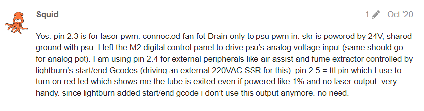
For laser power control I am using Pin 2.3 - fan fet. not pin 2.5 which was used for controlling peripherals and such (not any more). You should be good with either. I chose 2.3 just because this fet is slightly faster than the one used with pin 2.5 but both are way faster than what Co2 laser needs) Your drawing looks good (I think… thou wire from FET to L should be colored Black since we’re using PWM for grounding PSU laser control leg in order to excite the laser).
But, I am not familiar with your type of LPSU and so i cannot tell if the ports corresponds to my LPSU. you should be able to test and see without hooking up the laser if this tiny FET LED on SKR controller flickers/turns on and/or off according to lightburn power settings.

Whatever you try, use IR safety goggles and keep safe 
1 Like
Thank you for sharing.
I just started making CO2 laser machine. There are still many problems that I don’t understand despite trying to find out on google.
Fortunately, on this forum, I found a lot of knowledge from you.
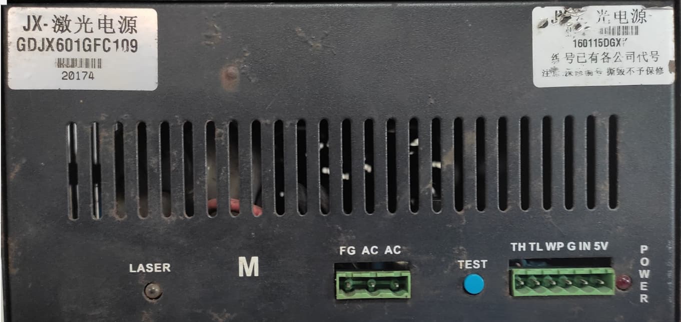
I have a photo of the actual power supply I have and can I redraw it?
Wish you much fun!
You should be using only the NEGATIVE leg of FAN FET.
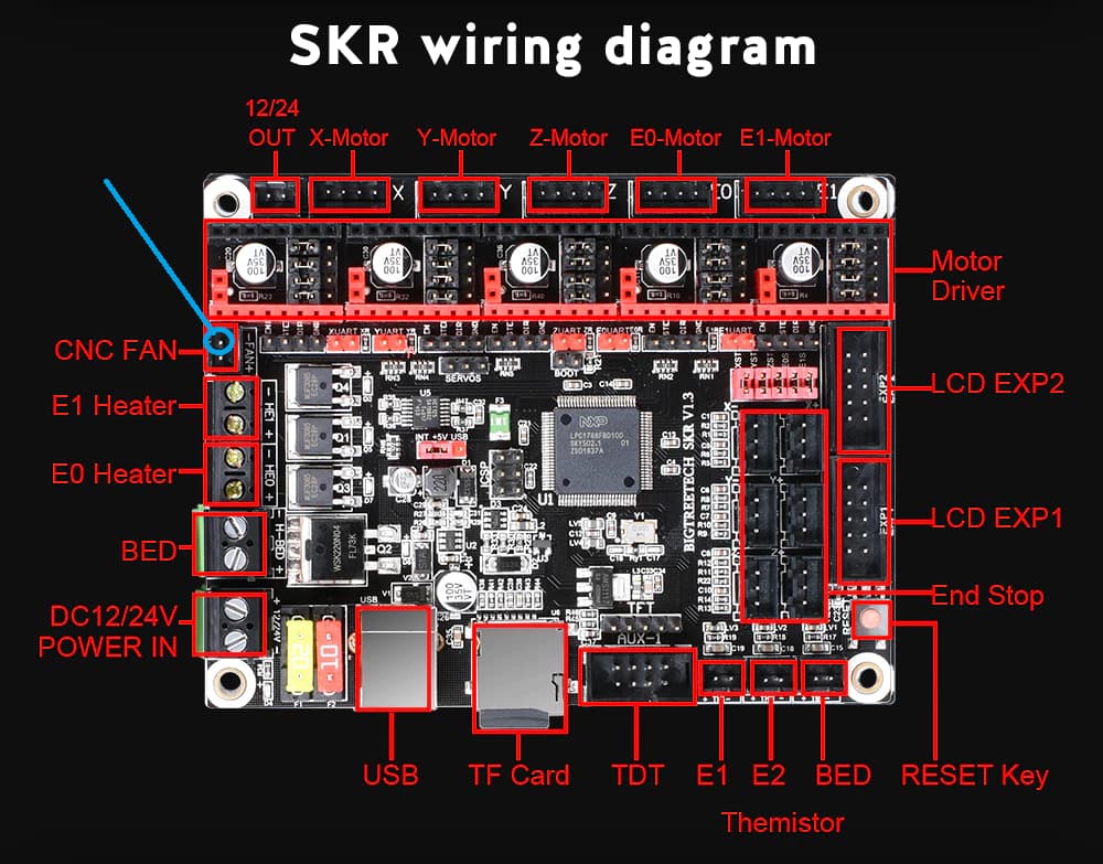
You can double check me - the bottom leg (Marked +) should be constant VBB and the top, marked (-) in blue should be the PWM leg which should be connected to LPSU. Again - before you hook this leg to LPSU connect it to a scope and/or avometer and check it to see it corresponds to lightburn power settings.
The laser should fire, again, not sure cause i never used your type of LPSU, when you ground the TL leg. be very careful if you try it manually cause the laser might fire at full blast if your pot is set for high power.
1 Like
I put pin2.3 and the led was blinking properly when I sent the command from LightBurn to SKR.
I only have digital avometer. I don’t know how to check if the PWM pin is working correctly. Please guide!

Can you tell the difference in led intensity between sending from Lightburn 10% power and 100% power? next you will need to be bold and connect it to TL with all the safety precautions required.
I measured at the FAN connection location, 10% = 3.7V and 100% = 24V.
Ok,…
Next you need to be brave and connect ONLY THE MINUS leg (-) to your LPSU “TL”
terminal. be very careful as this will excite the tube. your POT should be set to minimum now for making sure you are not going to overdrive your tube with a current higher than 15mA.
Good luck, be safe!
1 Like
Thanks a lot! I will do that another day. Today I just want every connection to be securely verified by someone as experienced as you. I will announce the good news when there is a new update!
Again, thank you for your enthusiasm!
np.
Just move in small steps and stop/power off if your setup does not work as expected.
Your power supply is different than mine so i can’t be 100% sure of the outcome.
there are more setting in smoothie config, pot settings , and so on…
Safety first. Good luck.
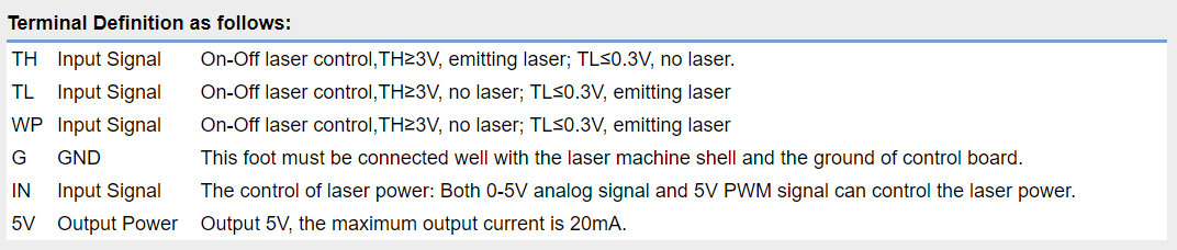
The terminal definition image you posted is correct.
TL means you drive it low and if fires
TH means you drive it high and it fires
IN means you send it a voltage that controls the intensity of the beam.
What does all this low and high talk mean?
It’s with respect to the ground an +5 v of the power supply. You can’t just hook it up to various outputs on that card. That is a very typical laser power supply connector with plenty of documentation on line.
Back on the power meter which is important so you don’t over power the PS or tube. I’m pretty sure it uses a shunt resistor. Meaning that nothing is going thru the meter which is just measuring voltage across the resistor. It’s been a while so look it up. Go go Lightobject and look at the power meter they sell.
1 Like
I’m using google translate so I can’t understand all the things you instruct.
I have not understood how the TL, TH, IN connection pins are related to each other?
Can you help me if something is incorrect?
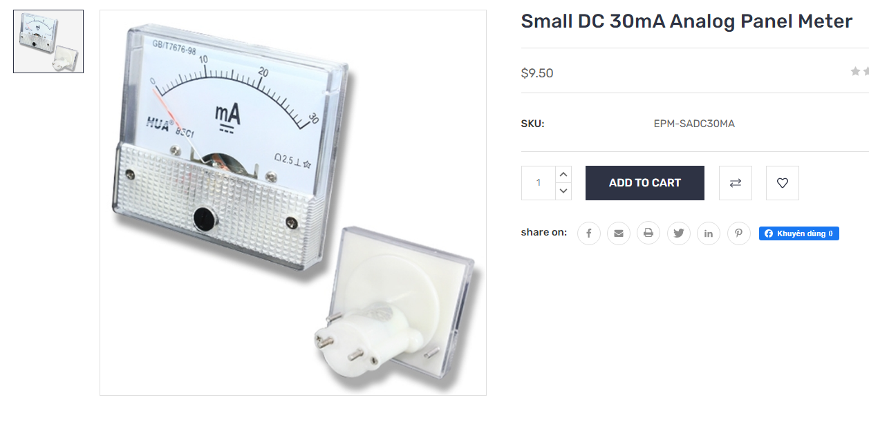
The mA meter I have is this one. Can I use it and connect like the diagram above?
Sorry this site doesn’t say when people need to translate.
Yes that meter will work fine.
I would recommend you first test out tube and power supply. Wire it up using this image. The controller needs to copy this circuit
Make sure you have coolant running thru tube. Protect your eyes and hands. Stay away from the red wire as it has 27000 volts.
1 Like
A next step could be to get a small 12v relay and attach it to the fan of the controller. Replace the switch with the relay Turn fan on which closes the relay and fires the laser.
You can make cuts this way. No photos.
1 Like
Great! Specific wiring diagrams like this are too good.
The switch connects to the WP pin and then to the G pin. So we pull the FAN- pin to the Power Supply as “Squid” instructs it to work as desired. POT to change the laser power.
I also learned about lasers and high voltage power supplies. I will be careful!
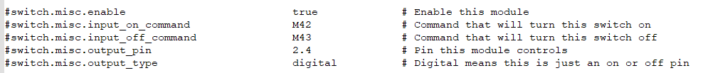
Are you talking about toggling the relay with G-Code like this? Replace the physical switch with a relay, then insert the g-code, like the picture of me setting output_pin 2.4. To enable I will insert the code M42 at the beginning of lightburn and end with M43.
If what I think is correct according to your instructions, it can be used to control the water pump, the air pump.
No. If you turn the fan on at the start it will cut all the time. You need to find a way to turn it on when drawing a line and off after the shape is cut.
I don’t use gcode in my laser but I’m sure something exists that turns it on and off like a pen plotter rising and lowering a pen. Or like a router that lowers the cutter to cut and rises it to move to the next cut.
This gets tricky. If there is any pause once it’s turned on, and before it moves, then it will blow a hole in the material. Not what you want for letters.
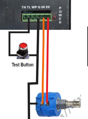
I suddenly remembered that there is no button to test the laser beam on the main control panel. Can you help me see if I connect like that?
Thanks alot…