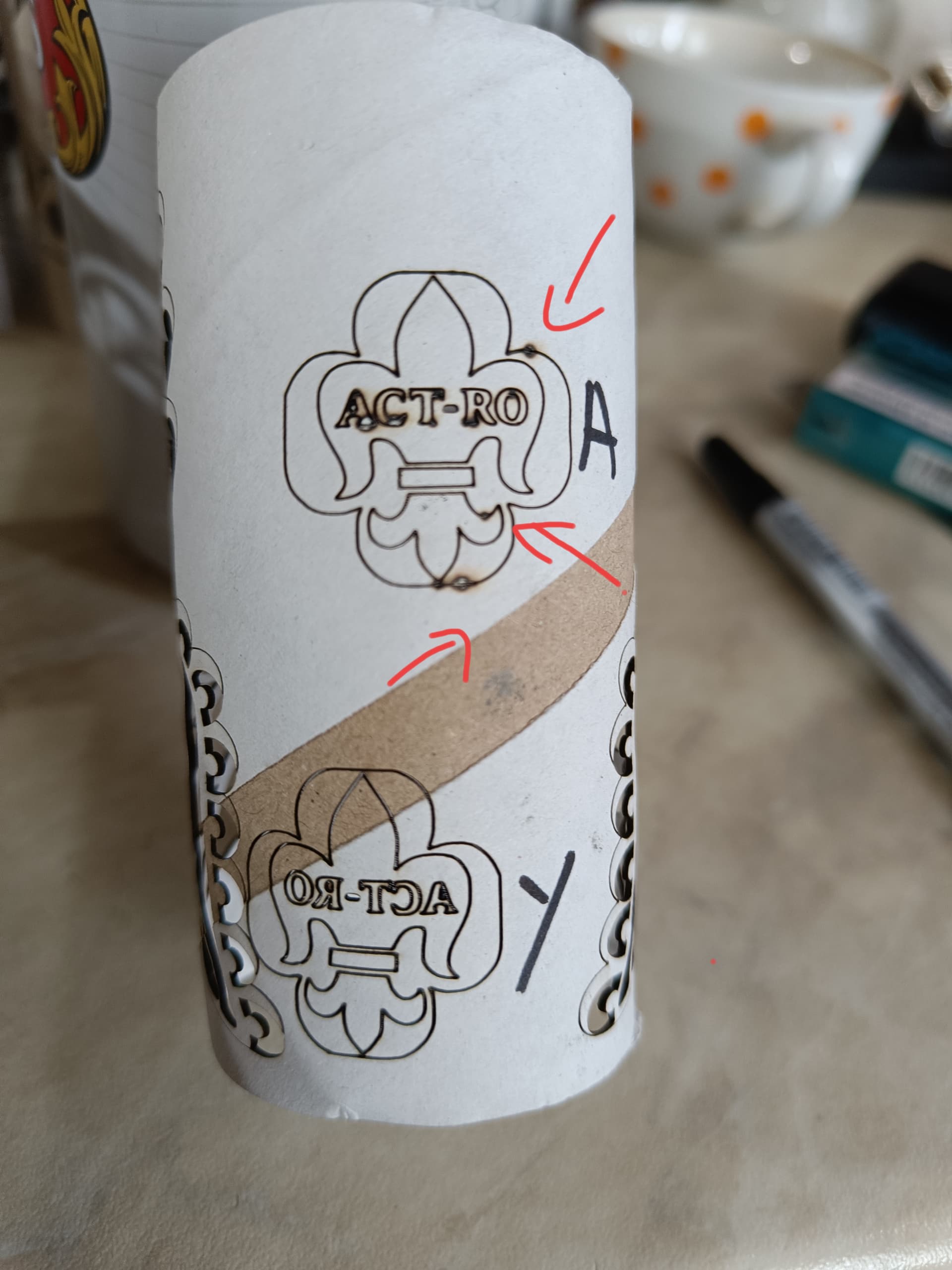
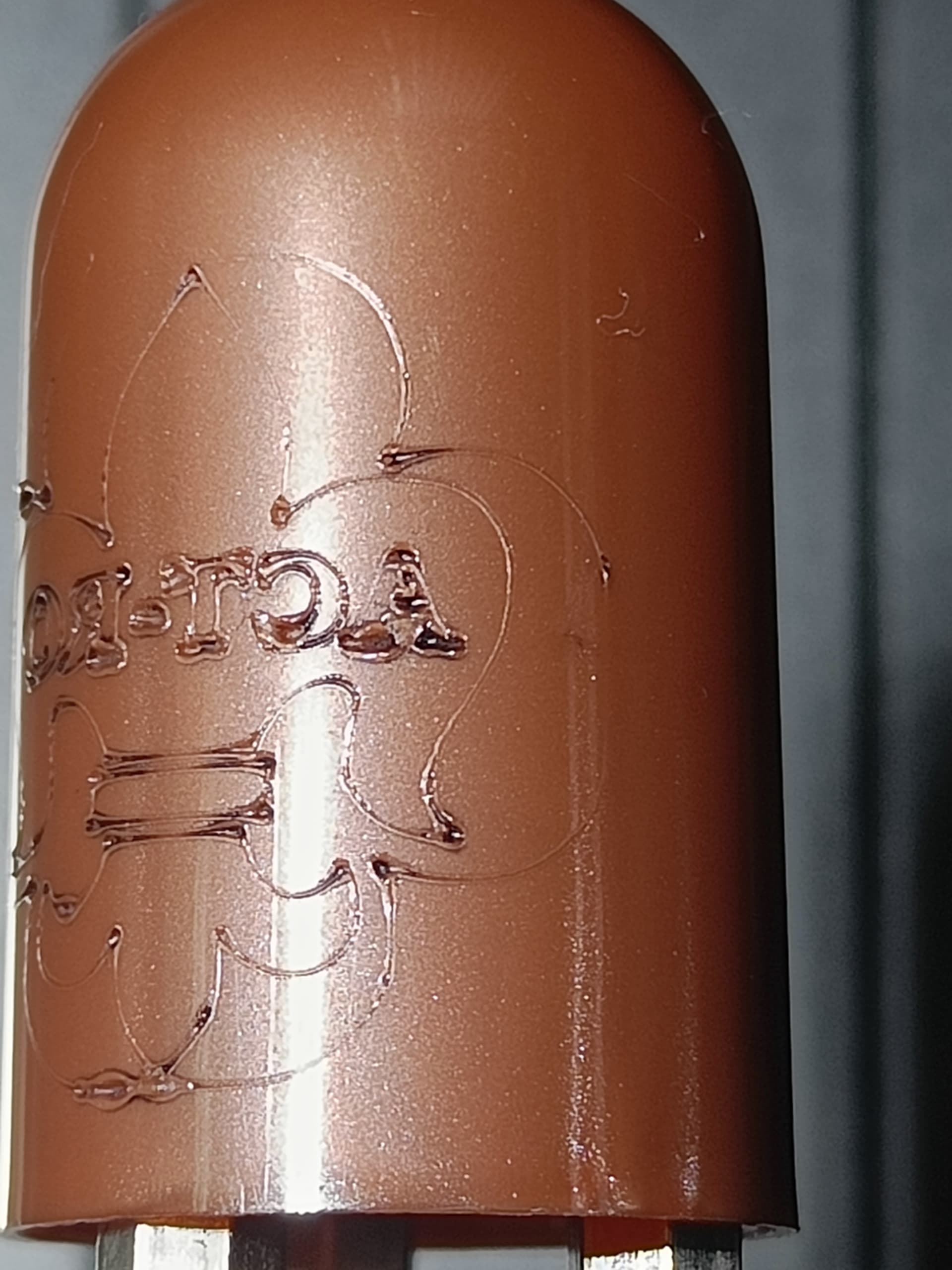
Hello @bLouChip @JackWong , now the A axis is ok with the new update, thank you @JackWong and @bLouChip but there is still a small problem. I have attached a picture. In the picture, the following can be observed: if I use the port for the A axis, it burns at the end or at the beginning of the line, and if I use the port for the Y axis, everything it’s perfect.I didn’t change anything when I ran the test except port A with port Y
Please post your .lbrn2 file,
save the GCode file, when configure for A axis, as .txt and post it,
and save the Edit->Machine Settings as a .txt file and post it.
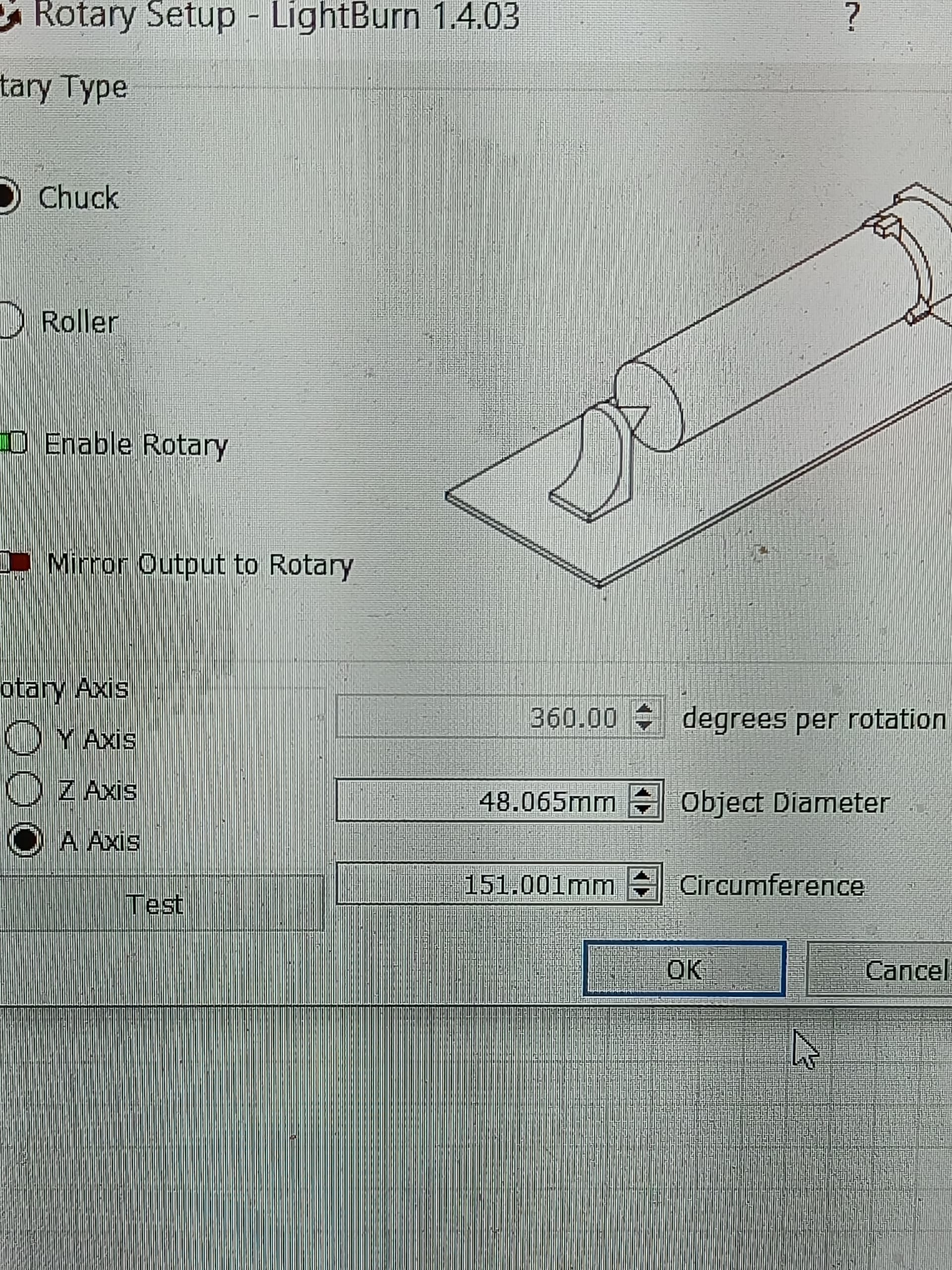
What is the cylinder circumference in the rotary configuration ?
1 Like
151 mm circumference
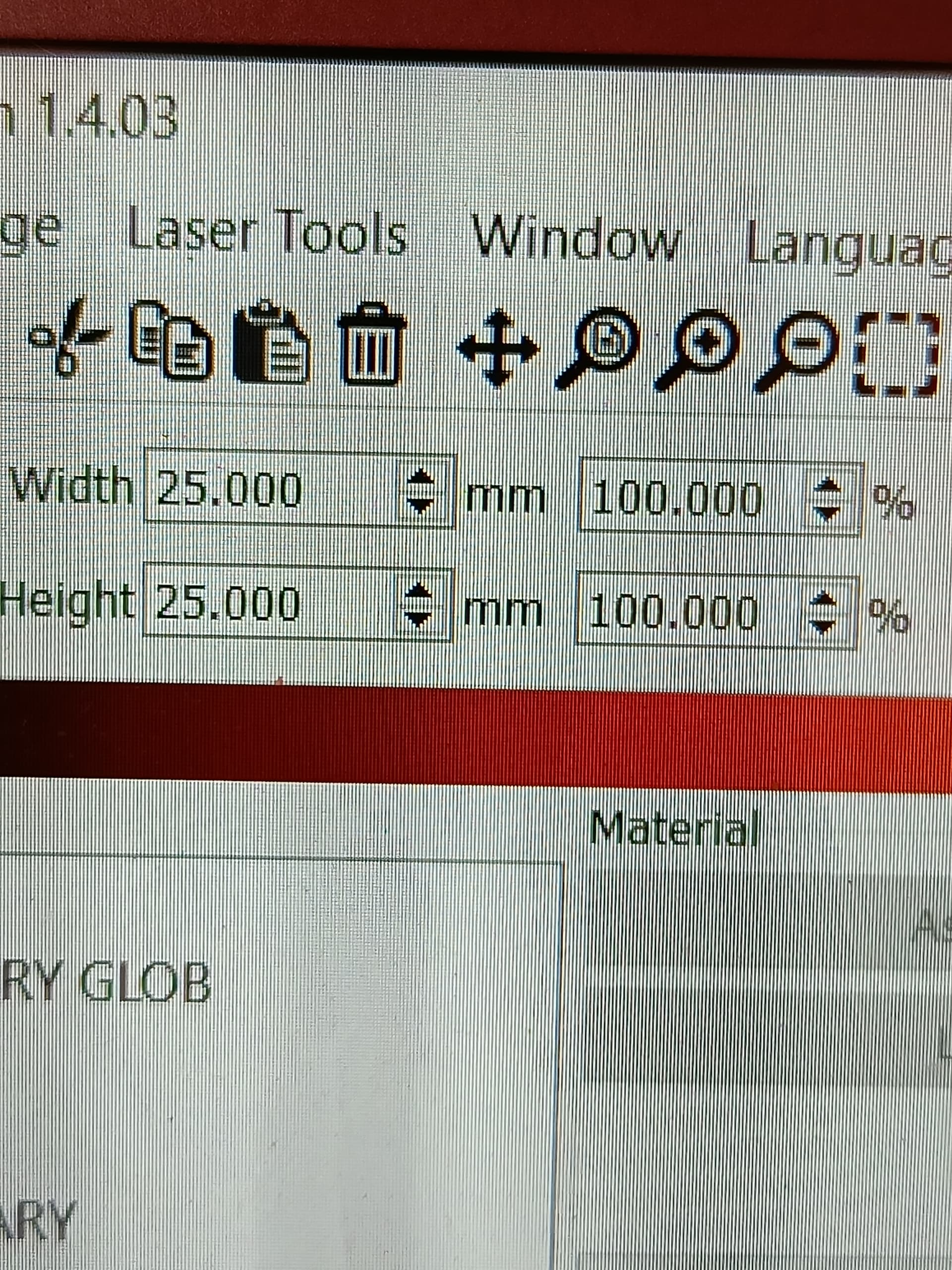
width 25 mm
height 25 mm
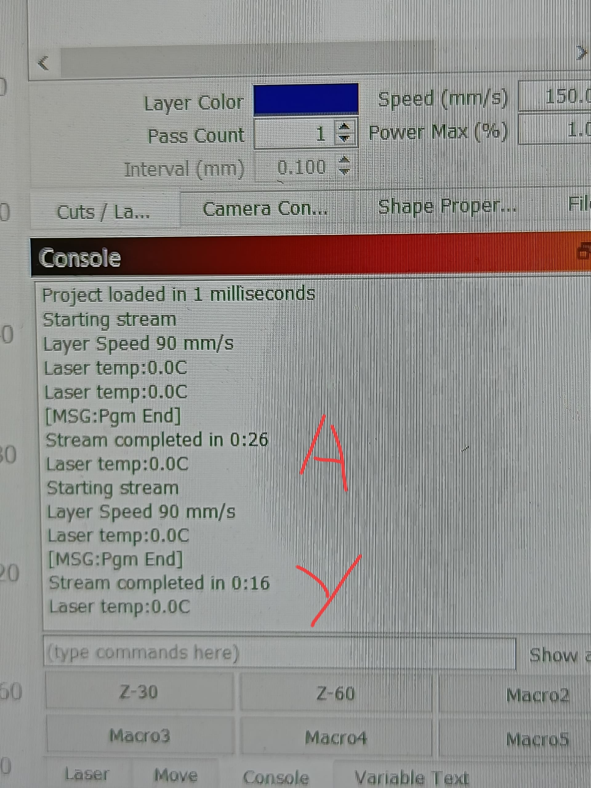
A execution time 26 sec
Y execution time 16 sec
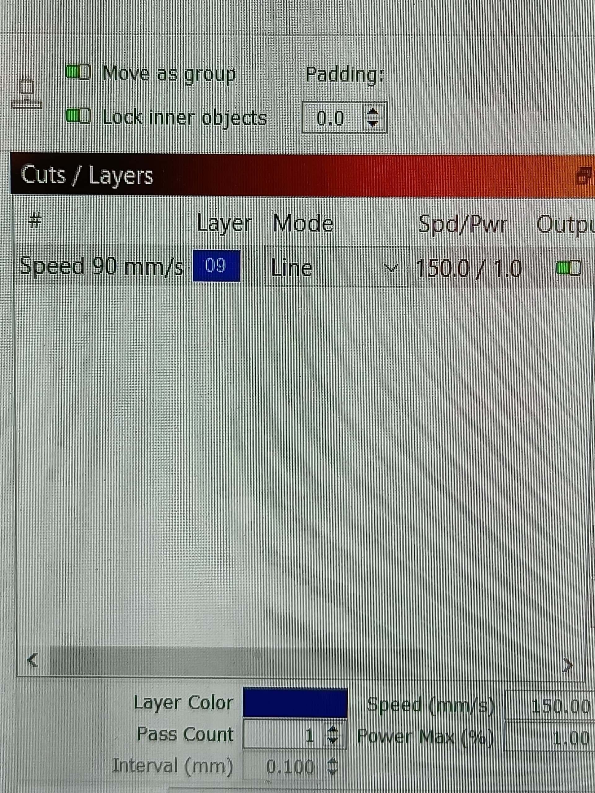
speed 150 mm/sec
A couple observations:
- reminder that -gofile.io- site has multiple viruses, I’m not using it. Please post those files directly to this forum thread.
- you’re still attempting to drive the A axis faster than it’s maximum speed of 250deg/sec. The cylinder surface speed is 150mm/sec, the cylinder is 151mm, that translates to 360deg/sec, exceeding your maximum. That may be the reason for the overburn in those locations noted on the resulting cylinder; notice those locations are at points perpendicular to the axis of rotation, which will max out the rotational speed.
- however, because every point in the toolpath that is perpendicular to the axis of rotation is not over-burnt, I’m suspicious that there is different issue at play, something I discovered on my machine when testing the similar version of this toolpath for you last week. The files to be posted will give more and perhaps conclusive information as to the cause.
- since the Y axis configuration can drive the rotary motor at the 360deg/sec, it stands to reason that you should be able to adjust the A axis maximum speed to 21,600deg/min (360deg/sec) in this case of this cylinder mass and circumference. However, I’d still like to review those files please for the other issue that I suspect.
@bLouChip ok ?
A axis rotary test.txt (24.1 KB)
Y axis rotary test.txt (16.6 KB)
Please post these 2 additional files.
![]() bLouChip
bLouChip
is that ok?
Max 4 modif.lbset (5.9 KB)
Max 4 modif.lbset (5.9 KB)
rotary test.lbrn2 (48.8 KB)
rotary test.txt (24.1 KB)
What is the cylinder circumference in the rotary configuration ? 150mm …the material used for test is a tube of toilet paper.![]()
After review of your files, I suspect that a second G94G1XAF rotary problem exists in grbl but one which I don’t believe is easy to fix, and I hesitate to call it a bug. G93 motion mode should not exhibit this problem, but LB does not have that option. The issue is that in G94G1XAF motion blocks that are very near perpendicular-to-A-axis motion, where the X distance is less than the X axis configured mm/step (1/(step/mm)) or 1/$100=value, that grbl will interpret those motion blocks to be X0 (ie no X motion, so only A motion) and thus assign the F value to A axis interpreted at deg/m, which usually means the motion is very very slow and will cause laser over burn. I experienced this on my machine last week when I first ran your Aaxis gcode. I wrote to LB Support to inform them of this potential problem then, they wrote back that they are looking into it.
In your Neje machine case, the X axis $100=80 (steps/mm), so that is 0.0125mm/step. So grbl won’t move X 1 new step unless the accumulated distance from the previously issued motion steps is at least +1 step. grbl keeps track of “residual step value” from the previous motion. So this means X motion less than or equal to 0.011 may or may not result in a new single step, it depends on the residual step (remainder) of the previous X motion.
There are 37 G1XA motion blocks in your gcode file that meet this criteria. I believe Oz @LightBurn or @JohnJohn is watching this thread so they should weigh in.
So @bLouChip in conclusion, who can solve this problem?
I trust it’s in good hands with LB to research, validate, and solve regardless of it being the problem I suspect or not. If it is that problem, then perhaps LB can program a “gcode axis motion minimum distance” of no less than the linear axis configured mm/step distance in these coordinated G1XA motion blocks.
Once again thank you for your support. If there are news I will be ready to test ;).
Hello, @LightBurn @bLouChip @JohnJohn do you have any news on my problem with rotations? Thanks in advance.
I’ve not heard of any news from LB Support regarding a fix.
Granted this issue does appear to be real (LB has not confirmed it yet) in the very narrow window of a line segment that is near perpendicular to axis of rotation, and it shows up very prominently in your test case of lasering toilet paper, which is an extremely thin, lightweight, and flammable material. Just curious, is the over burn noticeable on a more hardy material ? perhaps the material that you intend to laser in your project?
@bLouChip It is clearly a problem with the A axis, because if I connect the rotary to the Y axis and use the same settings, the result is ok, i.e. no burns. It is clearly a problem because if I change from mm/min to Inches/min the same project that is executed in 0.27 sec is executed (only if I change in inches/min) in 3:06 min.
rotary test 1.gc (25.0 KB)
Just curious…

What can I understand from your silence Lightburn?
1 Like
@mada , to be clear I’m not speaking for LB support, but I suggest you followup with an email to them.
I just noticed in a second review of your “rotary test 1.gc” and the related .lbrn2 file that you have defined your cut layer to use “constant power”. This may explain why you’re getting many more overburn areas/points than I did when running your shape. If there is no special reason to use constant power, try turning that setting off in the layer, and be sure to use a device profile of type GRBL, this will cause M4 to fire the laser as well as use variable power (proportional to realtime speed).
1 Like
Lou is on the right track here.
The M3 is emitted into the code because ‘Constant Power’ is selected.
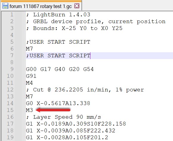
This could very easily be the primary cause of the burnt corners where the laser slows down and changes direction. Variable power is intended to prevent this among other things.
You may need to perform a Material Test to generate useful settings for Variable power.
Your command for 1% power is probably applying 100% power with the Constant Power setting selected.
Thanks, I’ll try.