Neje 4 Max issue with automated Z step commands

Hi !

I’m cutting veneer laminated MDF that is 6mm thick. I want to do multiple passes and adjust the Z height between passes.

What I envisioned was pass one would be at the Z level that I started with and the next pass the Z level would drop down 1 mm.

What is happening is the Z level keeps dropping at every change in shape in the work piece. With a start depth at 6 mm above the work piece the laser head keeps dropping and is quickly coming in contact with the work piece.
I do have order by layer on per a previous question posted from 2019.

The settings are :


I haven’t seen any updates on Z adjustments questions so I’m throwing this out to
see if what I want to do is possible, and if anyone knows any other setting that I may
have overlooked. I verified that when I manually tell the Z to drop 1mm it does only move 1mm.

Could you please share your LBRN so we can see how you built your project please?

also i see you on 1.5.04 not that it matters i think but have you tried updating to latest?

Is each shape on a separate layer?


I understood this occurred by layer… but I haven’t used it myself.

I checked the docs on the layer settings and didn’t see any explanation of it’s operation.

I asked @JackieG about it being documented, maybe I missed it.


You can search on Z offset and get a page or more of hits… Here’s one that might help…

Good luck

:smile_cat:

I use both Z offset and Z step per pass often. The only way I know to get the behavior you expect is to use multiple layers. The cleanest (IMO) way to accomplish that is to use sub-layers. Optimization won’t get you there, but can help fine tune behavior in conjunction with the sub-layers.

Here is a simple job I ran today. 5 shapes on one layer. Z offset, plus 2 pass, plus Z step per pass. I use a “base” or “park” z value and adjust height from there depending on burn requirement. My “base” height is perfect focus for the finest line engraving, but is approx 3.5mm too high for effective cutting, so engraving requires no offset value but any cuts do require an offset. My “first pass” cutting offsets are saved in the material library, so no extra thought or work is involved except for the sublayer modification. I “clone” then change the offset value.

Using a single layer, regardless of optimization settings or grouping, the five shapes are each effectively treated as a single job. Laser moves to shape 1, drops to offset height, makes 1 pass, drops by z step, makes second pass, then raises back up to start height. It then moves to the second shape and repeats, then the third, etc. For this job, that means 15 Z changes.

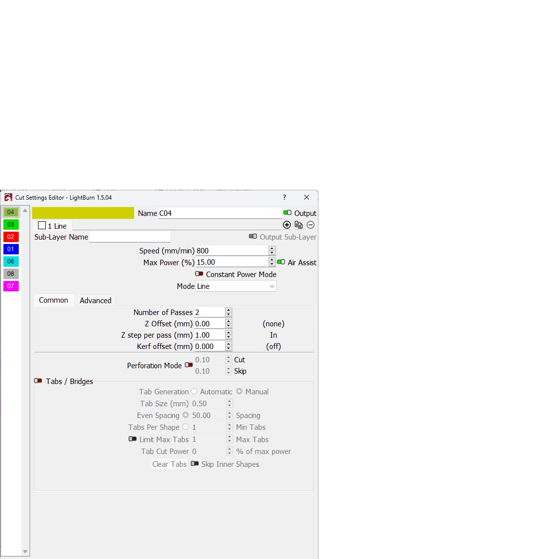
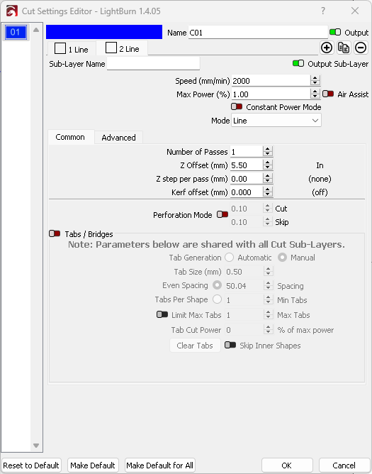
If you add a sub-layer (2 layers total, 1 pass per layer), it will complete the parent layer before moving to sub1. So, move to shape 1, z offset, 1 pass, move to shape 2, 1 pass, move to shape 3, etc. Once it completes all 5 shapes, it then executes the next sub-layer. ON MY MACHINE, to achieve Z Steps using this technique, I OMIT any value in the Z Step option. Instead, I add the desired drop distance to the Z Offset. So, if the initial offset was 3.5mm and I was a 2mm step, the sublayer needs a 5.5mm offset value.

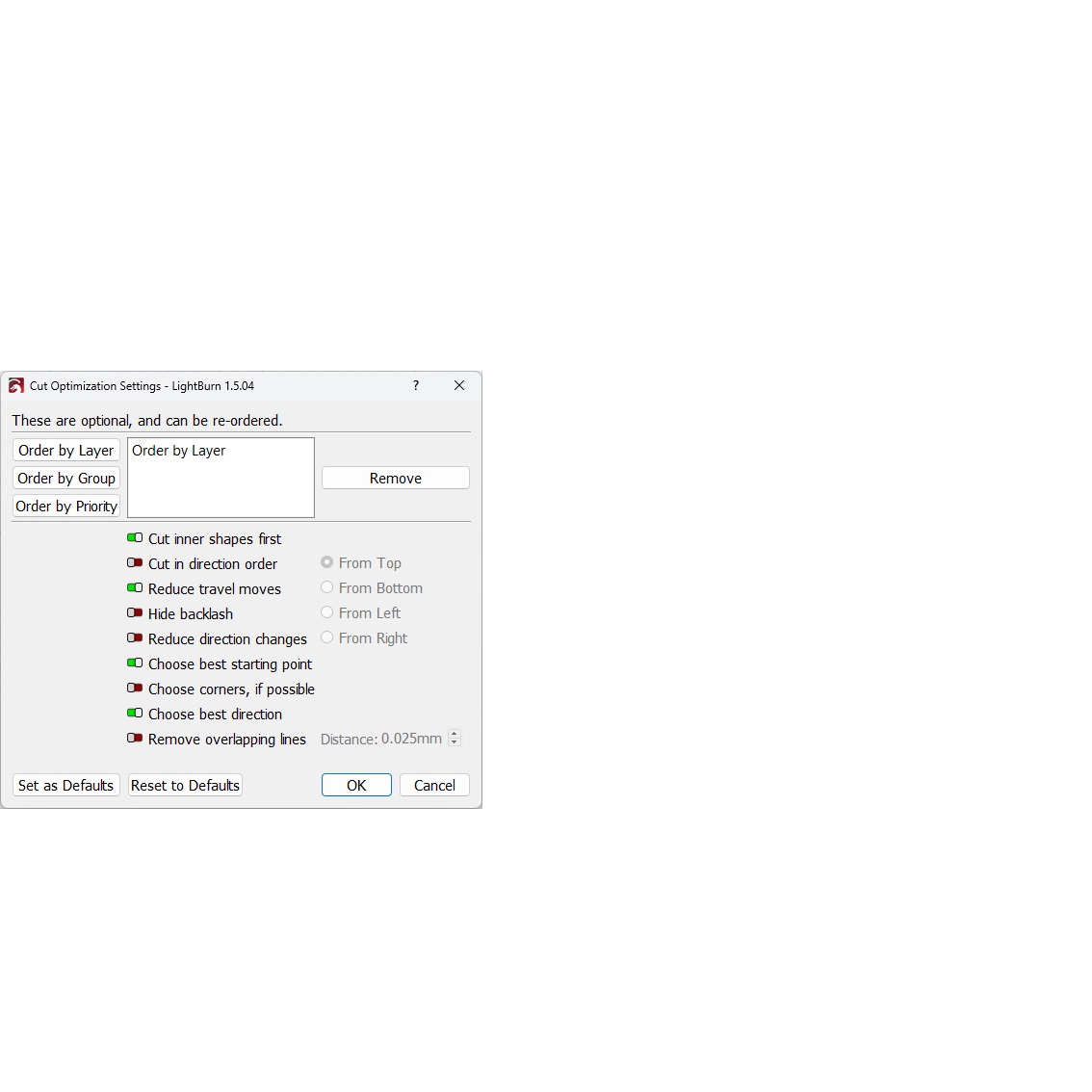
The next hitch is that, depending on optimization settings, the final shape of the parent layer becomes the initial shape of the sub1 layer. This means that particular shape gets cut twice with no pause or cool-down other the time it takes for the z move. This may or may not be a problem depending on circumstances. To work around this, you need to get you optimization settings right. There’s a lot there and I won’t pretend to know the impact of every possible variation, but I know what has worked for me.

Parent Layer

Sub1 Layer

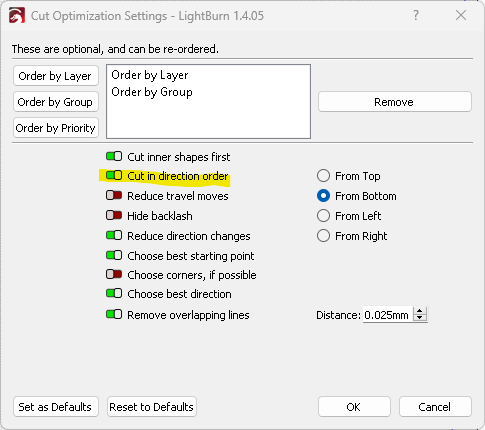
Optimization Settings
image

Using the setting above, this job has 5 z moves (instead of 15): z offset 1, pass 1 on circles, z offset 2, pass 2 on circles, raise to offset 1, pass 1 on outline, z offset 2, pass 2 on outline, raise to “base” height, move to finish position.

This ordering can be changed with optimization if you desire to have all 5 shapes run 1 pass, then step down and run the second pass on all 5 shapes, but it creates a fair bit of extra X/Y motion.

“Cut in direction order” seems to be the key to eliminating the back-to-back cutting of the one shape where the layer change occurs. Rather than doing that one back-to-back, it completes the shape then moves back to the (in this case) “bottom” and starts again.

You’ll probably have to try several variations to get the behavior you want. And it may well need adjusting on a per-job basis if you have specific needs.

Hey Chris !

Thanks for the response, below is what I just tried. I’ll try your suggestion and see if it works for me.
Much appreciation for the detail of the response.

All the elements of the design are on one layer.
I created a simple test file in lightburn that was two squares on one layer and instructed
it to make 3 passes and drop 1 mm on each pass.
I confirmed that it cut the first square at my 6mm initial setting. It then repeated the first
square dropping 1 mm at each pass. Then moved to the second square starting at 4mm above the work then made one pass and dropped 1 mm, then another pass dropping 1 mm. It never raised the z axis.
I assumed it would cut both squares on the layer for the first pass at 6mm above the work surface, then on the second pass drop to 5 mm.
I turned off all optimization, tried toggling relative z moves only and neither adjustment made a difference.

I suspect the Z behavior will vary by machine. I am using an Ikier K1 and these are my device settings that work very well, IMO.

(ignore scanning offset. I’m in the middle of some testing there, so it’s temp empty.)

Chris, the sub layer usages achieved the action but not the result. Creating the sub layers (2) burned both squares at 30 mm above the work surface, then dropped for the second sublayer and dropped again for the third.
I exaggerated the initial Z height (30 mm above) and dropped 10 mm for the second and third sublayer passes to observe the movement in greater detail with the power set to .5

So many many thanks for that suggestion !

The issue I’m realizing now is, while I can move the Z axis on the move page up or down a measured and repeatable amount. The movement that the sub layer is effectively doing is erratic and inconsistent but, it is moving.

In the machine settings, I tweaked Z steps per mm and saved it to reflect the correct movement when using the up and down Z settings on the move screen but the sub
layer is not moving the distance that is requested.

I’ve looked for another Z setting that may be incorrect but I don’t see anything that I can think of that would be relevant. My Z works perfectly otherwise, it is measurable and repeatable.

I’m going to try to find a factor that maybe works for the sub-layer, desired value times 3
may be the number based on observation.

Very curious.

Make sure I understand correctly.

You can use the jog buttons with a set distance value, and a single click produces the desired movement distance and direction. Ie, command 10mm down, it moves 10mm down.

However, when executing a job, the movement distance is not only the wrong distance but it’s also not always the same distance? Ie, command 10mm down, it may move 3.2mm down on one pass and 4.1mm on another?

I believe there are other Z motion behaviors used for the CO2 machines but I’m not at ALL familiar with those. Something to do with a Z origin, reference height, and offset. To me, it sounds like they use absolute positioning. My machine does not work that way and it’s my only experience using Z and Lightburn.

Yes, that is correct. It functions perfectly using the jog buttons after I adjusted the Z MM/m setting when setting it up, but erratically when the command is automated.

I CAN cut the 6mm MDF in one pass, but there is a very fine
wood veneer on top that scorches, so I wanted to make two pass at low power to get
into the MDF then power up to complete the cut. The MDF is tough to cut but I like it for the dimensional stability and warp resistance. But I may have to rethink using it as
it slows down production if I can’t accurately use the automated Z moves.

Your suggestion got the Z axis to move AFTER completing the layer so I do think there is a possibility that it can be worked out. I don’t understand why the Z steps per pass, or Z offset does not function as expected, but as you said each laser/controller combination is different. I haven’t upgraded to the latest release because we are in the middle of a production run and I don’t want to risk missing a deadline for a machine issue, not knocking LIghtburn at all, it’s an amazing product, but as each machine responds differently I don’t upgrade until the project is complete.

Thanks again !

It may be worth a topic title change or new topic that specifies Neje Z axis to help focus in on the correct responders. I know we do have several Neje Max owners here. I wish I could help more.

Great Idea, done !
Thanks again, you’ve been very helpful.