Hello,
I need help from Neje Max 4 E80 users.
My problem is the accuracy of cutting plywood.
At first I suspected the error in Lightburn. But the fault is definitely not Lightburn’s fault. The G-code generated is exact.
That’s why I contacted Neje. Ultimately no solution was found. On Neje’s advice, I optimized the Neje Max 4 several times in terms of belt tension and replaced the pulleys. The result hasn’t changed.
I would therefore like to ask users of a Neje Max 4 E80 to test my file on their Neje Max 4 and let me know the results. So that I can possibly narrow down the error more closely.
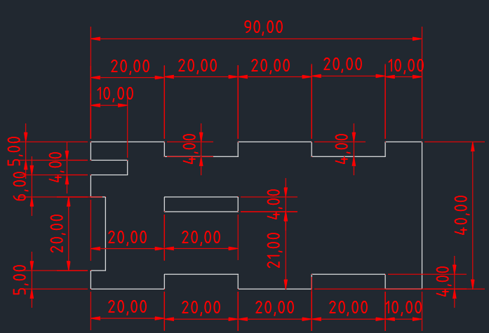
It is a simple template made from 4mm plywood with a few cutouts. Other and thinner materials can also be used.
Strangely enough, the overall width of 90 mm fits pretty well. But not the 20 mm wide recesses. Furthermore, the overall height is too low, but the height of the recesses is again greater than 4 mm.
One of the problems may be in how you are calibrating your axes. Looks like you’re calibrating to an outside cut of material. This means you’ve hard-coded adjustments for kerf in your measurements.
This could have the effect of potentially oversizing outside cuts and undersizing inside cuts.
Instead, I’d suggest calibrating like this:
focus your laser to the finest dot possible
burn to a material that will show the finest possible line
use the minimum power required to make a mark so the line is as thin as possible
burn the largest possible reasonably sized square using those settings
measure and calibrate
This approach assumes that the laser is essentially infinitely thin and you’re calibrating to nominal distance movements.
Once complete, this will not get you dimensionally accurate parts since kerf is a real thing. You will need to add in a kerf compensation either manually or using cut settings. Note, however, that diode lasers typically don’t have the same kerf both vertically and horizontally. So you’ll either have to compromise on the kerf value or manually compensate horizontally differently than vertically. Or perhaps make cuts at a 45 degree angle.
Note that material differences can also affect your results.
The errors appear to be about what’s expected for a non-square diode laser in fairly thick material: off by about 0.2 mm parallel to the X axis and 0.4 mm on the Y axis.
Because the focused spot is not square, LightBurn’s kerf compensation won’t be quite right, but it will certainly get closer to the nominal dimensions.
I you did the axis calibration using cut-out pieces, then the calibration will be incorrect due to the kerfs. Re-do the calibration with the laser set to mark, not cut, paper or cardboard, then measure distances center-to-center on the marks.
If I do that, then the outer contour will be smaller when cutting due to the burn?
But then the external dimensions are no longer correct, are they?
But these are just as important to me as matching cutouts.
Kerf doesn’t affect the external dimensions, does it?
The purpose of axis calibration is to make the machine move exactly the programmed distance on each axis, which has nothing to do with cutting. That’s why you must do the calibration center-to-center with marks on the surface: the width of the mark does not affect the result.
When the machine is calibrated, then you apply kerf compensation to put one side of the cut exactly at the nominal dimension.
I generally do not use per-layer kerf compensation, because keeping track of which way it will be applied seems overly error-prone (at least for me). Instead, I apply an offset to specific shapes, so the resulting outline is the right size. Reasonable folks have differing opinions on how to apply kerf compensation, so do whatever works for you.
It certainly does!
The laser beam cuts (roughly) the same amount of material on both sides of the nominal dimension on every cut, so (when you care about the exact sizes) every shape must have kerf compensation of one sort or another.
@ednisley @berainlb
Hello,
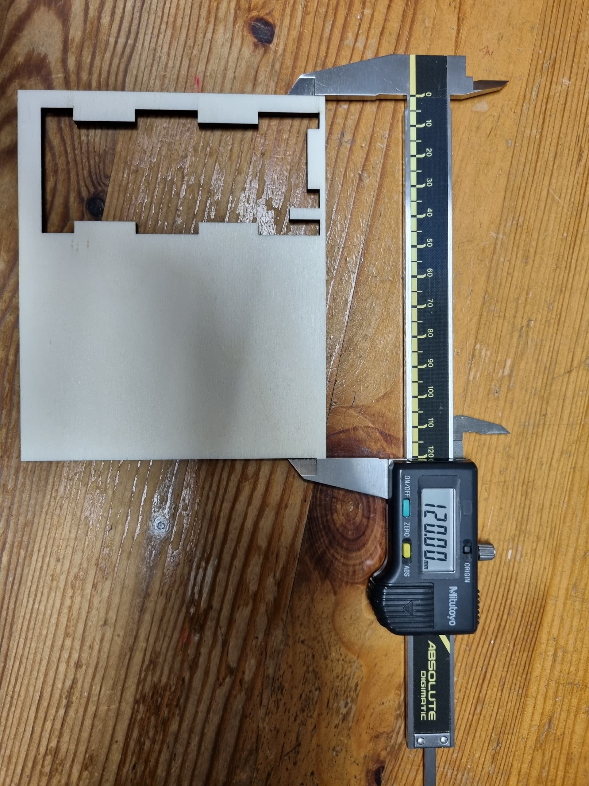
I have now carried out further experiments. According to your instructions, I recalibrated the laser with a rectangle of 100 x 100 mm. In order to get the exact outside dimension when cutting, I had to insert a KERF = 0.35 (2 passes when cutting). The result was then X = 100.07 and Y = 100.4 mm.
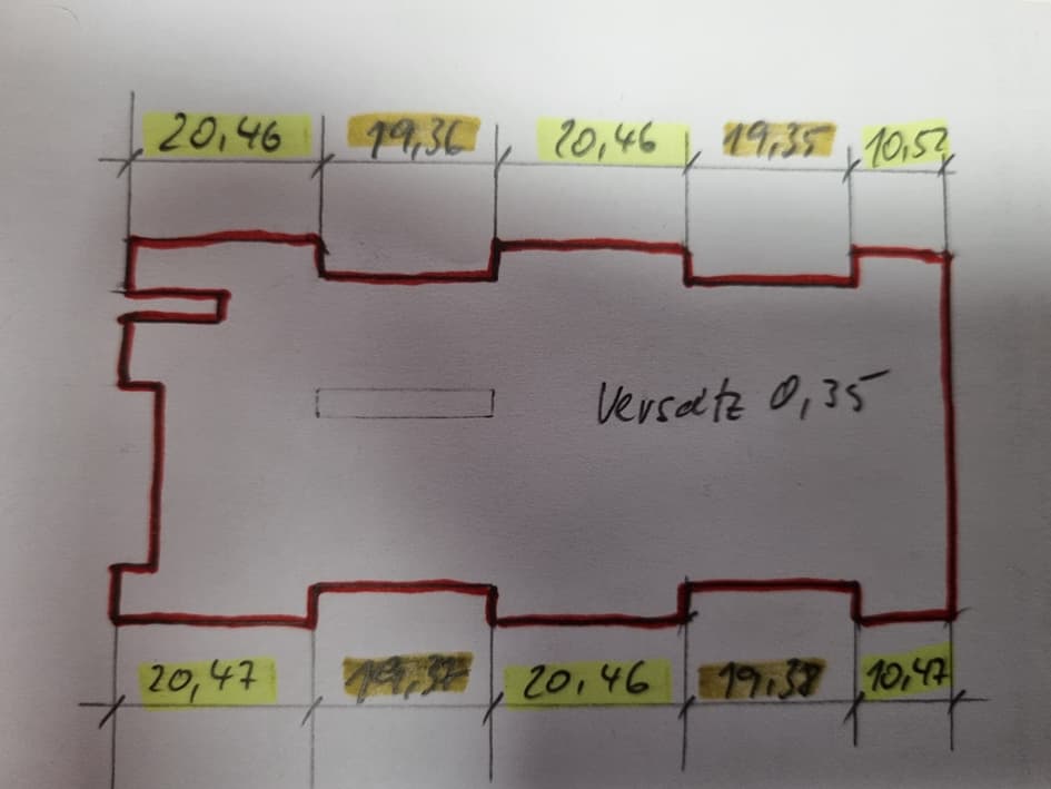
Here are the results of my test part:
To me it looks like Lightburn isn’t applying the KERF correctly. Could this perhaps be due to the drawing? Maybe vectors are in the wrong direction and Lighburn is adding or subtracting something incorrectly? What is striking is that all the incisions are uniformly narrower.
Tonight I’ll give the offset another try.
Start by measuring the kerf along both X and Y axes, perhaps with this tool:
Do that for whatever material you’re cutting, using whatever settings are appropriate. The non-square laser diode spot will likely make the X and Y kerf different, which means you will be unable to pick a single value to optimize the dimensions in both directions.
LightBurn follows very simple rules that sometimes conflict with our more complex expectations.
After you measure the actual kerfs for your machine, practice with simple shapes, thin cardboard, and single passes to show how the offsets apply. In particular, measure the size of holes in those shapes, as well as the effect on notches and protrusions along the edges.
Applying absurdly high kerf and offset values helps me visualize what’s going on: there’s nothing like having a hole vanish to remind me I’m applying an offset in the wrong direction.
The kerf width depends on the material, speed, power, passes, and direction. You may find a single value that’s “close enough” for what you’re doing, but you may also need to adjust your designs to match the ability / accuracy / repeatability of the tool producing them.
I’ve learned not to expect accuracy closer than about ±0.2 mm from the nominal size for any particular part in repeated runs, even with the round spot of my CO₂ laser.
On top of @ednisley has already indicated can I suggest you try one thing. Instead of trying to cut-out the shape. Try removing kerf and engraving the design using the same settings you used during the axes calibration process.
I’d like to confirm that your machine is actually moving as expected and we’re not dealing with some sort of mechanical issue as yet.
Hello,
I will come back tomorrow.
Today’s experiments have not yielded any new insights. I’ve found that measuring the engravings with a caliper doesn’t produce great results. The course of the wood fibers has a significant influence on the engraving accuracy and the measurement result.
I have now carried out various experiments.
I can say that the engravings are quite accurate. The 20 mm wide depressions and ridges are all the same size with slight tolerances.
Things look different when cutting. Here the elevations and depressions each have the same dimensions with slight tolerances. It doesn’t matter whether I work with a Kerf or an Offset. I can’t explain the reason for this:
Normally all 20 mm wide cutouts should be of a similar size.
I have now watched countless videos on this topic. I’m the only one having problems making a connection with prongs and tenons.
For me at the moment the offset isn’t the problem. I think I can solve the problem. The depth of the cutouts fits quite well.
I don’t understand why the widths of the 20mm cutouts are different and why these widths are also different depending on whether the laser is traveling along the top and bottom edges or cutting a recess.
Whether using offset shapes or kerf you’d want to use half the kerf size as the offset value.
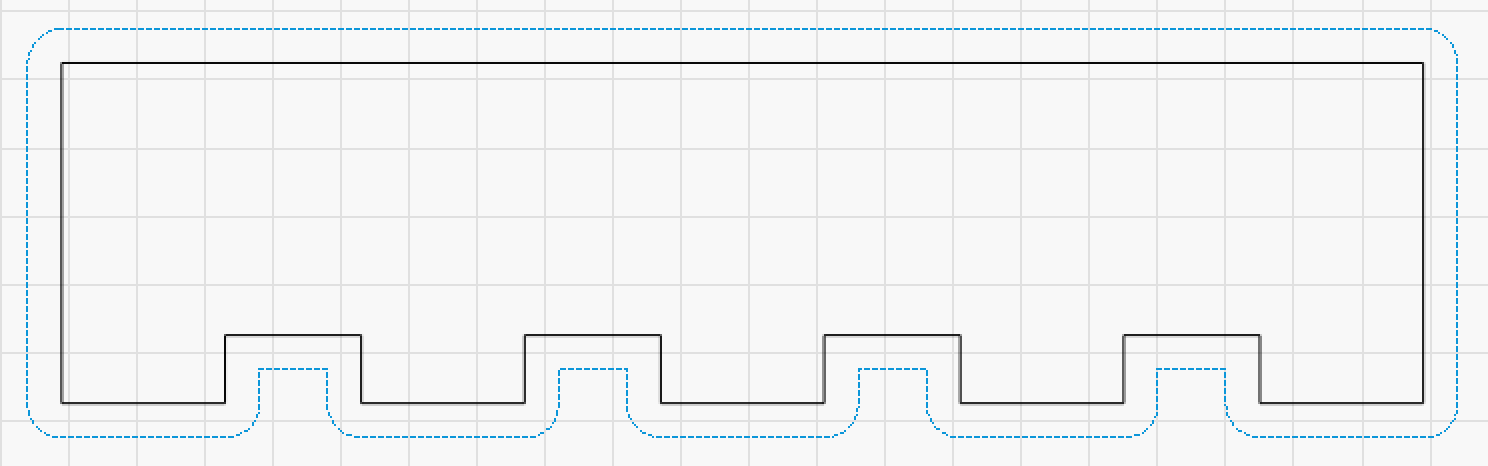
The outset on the outside of a closed shape will have it grow. The result of this is that tabs will get bigger and slots will get smaller. You can see this if you exaggerate the size of the offset. This is why it’s important to apply the correct amount of kerf/offset.
I understood the offset with half the width of the laser beam.
But the fact that the tabs and slots should have different widths doesn’t enter my brain. In principle, I compare the laser spot to a milling cutter on my CNC. The cutter moves along the contour at an offset of half the cutter width. This has never had the effect that the tabs and slots had different widths. Well, the diode laser spot is not exactly round like a milling cutter. But the lateral removal in a tab or slot would have to be the same because the laser beam does not change direction.
In my opinion there is a bug in Lightburn. Or I don’t understand the system yet.
I will continue my experiments and try to optimize the cuts so that they fit my laser.
I don’t understand how that could be the case. Perhaps because there’s little variance in measurable kerf size using a solid bit.
Did you review the diagram I included above? You can visually see how the slots will become narrower any why getting the correct kerf adjustment value is important. Having too large a value will result in tabs being too large and slots being too small… Having too small a value or no value will results in tabs being too small and slots being too big.