Hi there, ever since downloading the latest version I have been having issues.
I’m still fairly new and struggling with the changes just when I was getting my head around the old version.
So, using absolute coordinates. Offset pointer is enabled. Turning it off makes no difference.
All my framing is about -20 mm off on the Y axis.
Have restarted numerous times and done $RST+*.
Same issue continues. At my wits end now.
Also when I move the laser to 150x100 coordinates it is off by X: 2.5 mm and Y: 0.5 mm. I have adjusted these values on the enable pointer offset. When I move the laser to 150x100, it is still out. Like the adjustment is just not registered even after fully restarting.
Turn off Pointer Offset and make sure everything is correct. A box should burn very close in size to the design size. A designated corner should be burned at the position indicated by the design, using Absolute Coords.
Read the Lightburn docs on Pointer Offset. It is the pointer that is offset, not the laser.
- Burn a spot. Record the X and Y positions.
- Jog the laser until the pointer is dead centered on that spot.
- Record the new X & Y coordinates. The differences in the X & Y values is what you enter in the Pointer Offset value boxes. Correct for polarity if the offset goes the wrong direction.
Hi Mikey, thank you for your reply.
I followed this method exactly: Laser Offset Setup - LightBurn Documentation
I find it very confusing since it specifcally says to use current position, not absolute coordinates. When I enter The offset value and turn it on, I can see no difference.
What really bugs we is that if I send the laser to 150x100 mm on mm paper, it clearly goes to 148.5 x 99.5. Or maybe it is the pointer as you say.
I will need to to mess around with this more tomorrow. I started at 12 midday, it is past midnight here now and it still off.
Before you mess with the Pointer Offset, fix this first. Is it an axis calibration issue? When Homed, does it show 0,0 or a slight offset? Is there something in the G54 ($# in Console) parameters? Use Absolute Coords for this testing.
I do not use this feature, so the Lightburn documention rules.
Hi Mikey,
Thank you for your help.
The “framing 20 mm out” issue currently seems fixed. The camera was misaligned.
But, I have no idea how to fix the other issue.
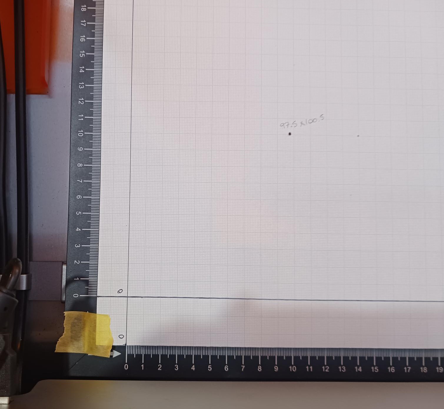
On the photo (from absolute coord), I entered 100x100 and pressed go, then fired till I got the small hole. As you can see it is 97.5 x 100.5. On the workspace, laser position shows as 100x100. Pointer offset was off for this.
The mm paper is stuck on 7mm carboard, so it may look a bit out of line on the photo, but I assure you it is in exact position 0.
When homing, it shows X:0 and Y:0
What do I need to do? And where and how do I do it?
I have a Genmitsu L8 40W.
Pulse/burn a dot while at X0 Y0 as a reference check to see if the burn dot actually lands at X0Y0 as you have marked on the paper.
The graph paper squares do not appear to be remain consistent with the measurements on the honeycomb frame?
The Laser Offset should always be disabled unless you have a separate “pointer” laser used during framing that is offset from the main output beam.
Haha, you did not mention you were using a camera!
I do not see a hole at 0,0 so how do you know it is not also off there as well? I have never used the honeycomb scales to determine position.
To check calibration, you need to burn a 100mm x 100mm square. Then measure it.
This will also check positioning accuracy. But I seriously doubt you have enough issue here to worry about.
Hi Nicolas and Mikey,
Thank you so much for assisting me.
I did what you said.
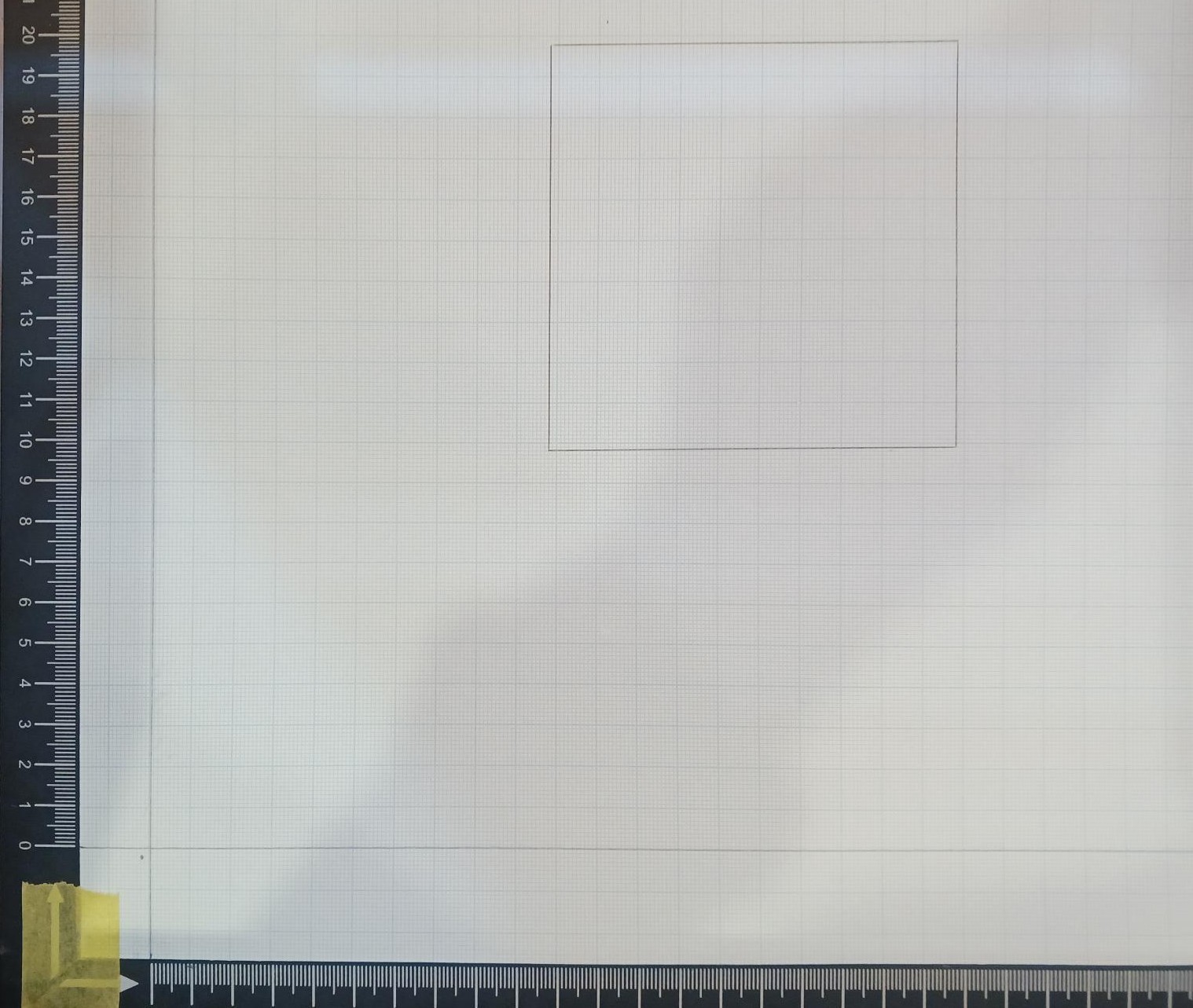
Clearly the physical workspace of my laser is -2 x-2 off from the workspace in Lightburn. The square is 100 x100 and is in the correct position from the 0x0 dot. This is good to know.
Unfortunately, it doesn’t explain why my work is always a little bit misaligned using the camera.
This is the stuff that I do:
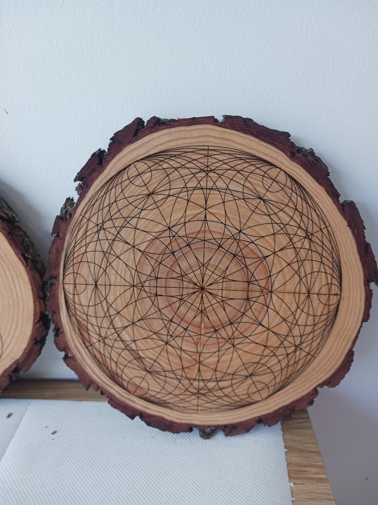
I always start with full calibration (clearly something went wrong with the alignment the other day), but this is a consistent issue.
I make several camera adjustments to get the measurements right. Since the wood is about 20 mm thick and therefor closer to the camera than the workspace, this changes the measurements.
But even when I have everything perfectly adjusted and aligned on the screen, it always burns that little bit off centre.
I’m starting to wonder if the X and Y axis have also shifted a bit on the camera. But I don’t know how I can check that.
Any thoughts?
Hi Mikey, please check my reply to Nicolas. Thank you
For your machine, you will need to align the camera image by burning the alignment pattern onto a material thickness of 20mm or as close as possible to the thickness of your wooden rounds. Otherwise you will always have issues.
Ideally you will specify what your material height is during the alignment, this is a brand new process not yet well documented.
If you don’t see any place to specify material thickness during the alignment just proceed (I’m not sure what all the reasons are for this to be hidden, I had difficulty with this also and am trying to find out more).
Immediately after alignment at 20mm you should confirm that the alignment is correct by setting these values all to zero:

To check everything, mark a shape and ‘Update Overlay’ and check that the shape in your workspace aligns with the burn marks now showing in the overlay image. Since you have just completed alignment, as long as you are using the same material height, it should be spot on without any adjustment needed. Toggle “Show” off/on on the layer to confirm the shape is perfectly above the mark you made:
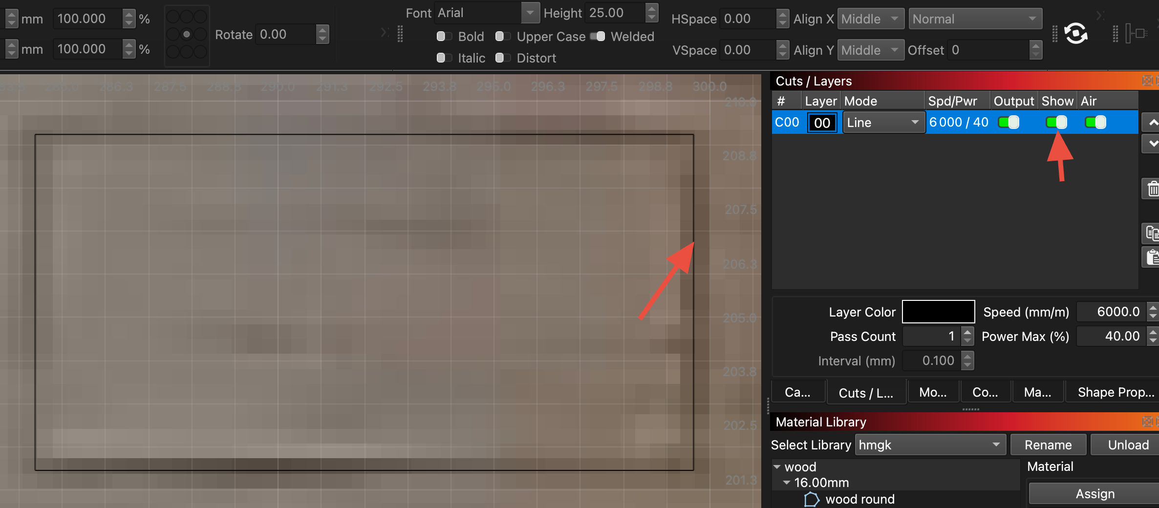
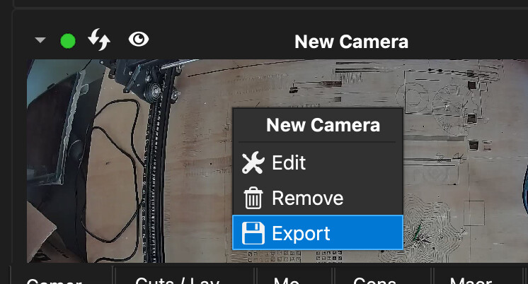
After doing this you should be good to go, but it’s a good idea to right-click on the camera image and “Export” your camera settings, especially if you could not enter material thickness during alignment - then name the file something like “camera_aligned_20mm” and I’ll give you some more instructions if you need to use the camera at other heights also.
That makes a lot of sense. Thank you
I don’t have material atm, but I’ll give it a go in a day or two.
Would it not be the same procedure for other heights? I’m expecting up 40 mm material.
Yes, in the new version there is no longer a box to enter material thickness. The old version had this.
I did everything that you said and it is a huge improvement. I only need to make minor adjustments along the way. I assume this is due to material thickness variation between pieces.
Thank you so much
Yes, that is one way you can do it, after saving/exporting camera settings with a title that represents the material thickness.
Note: It is currently best in 2.1.02 to start a new alignment for a thicker material by clicking on this button: (I had some problems saving new alignments initated from the Edit Camera area)
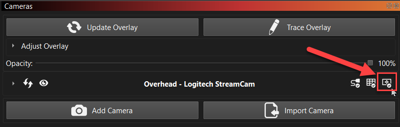
Then save/export your camera with a new name, and change camera settings by removing the existing camera and importing the appropriate one when you change materials.
The GRBL device does not yet benefit from the new material height control and interpolated height improvements discussed in the forum post. However , there is an another way to at least set up multiple alignments for a GRBL device with the correct thickness showing in the saved alignment (rather than always “0mm”), by manually editing the alignment record in the camera settings file: For example, I change these values to 16mm:
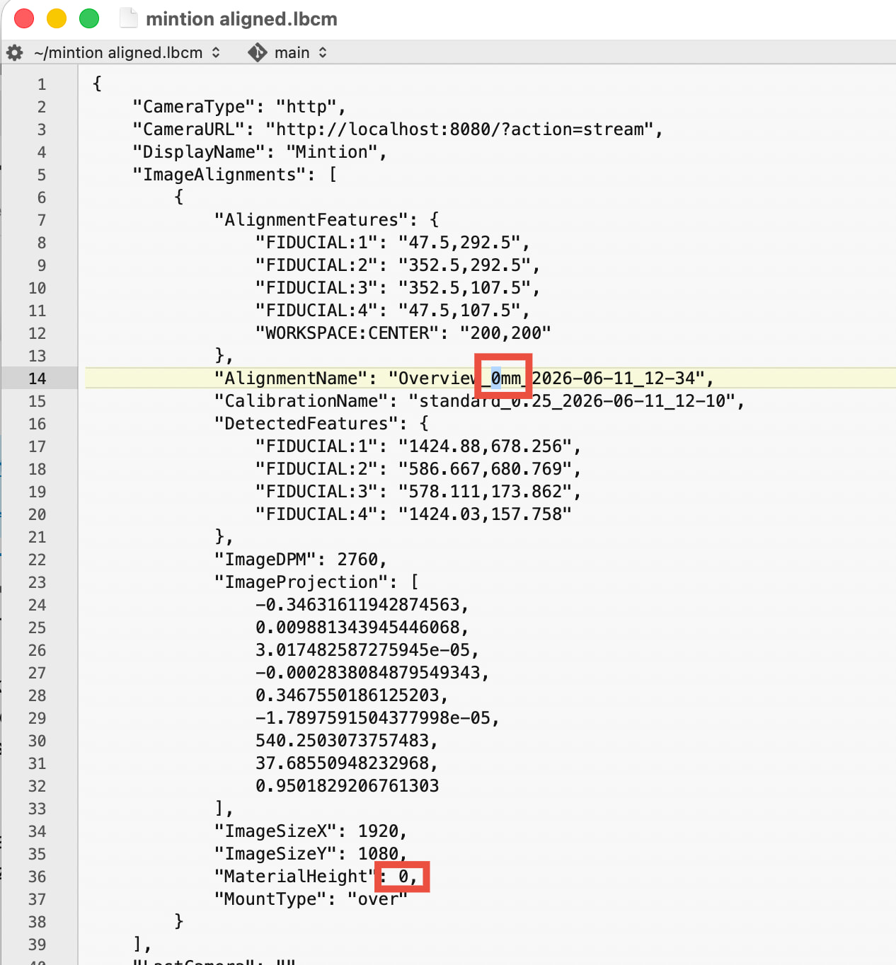
Then, if you load your original camera that was set up and aligned for 0mm material, edit that camera and in the ‘Workspace Alignment’ section ‘Import’ the camera settings edited with the new material thickness, the 16mm alignment will be found in those settings and added to the currently loaded camera.
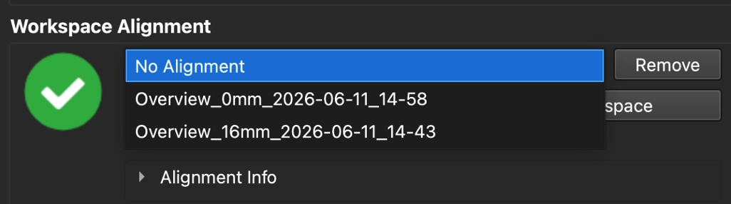
Now when you change material, right-click on the camera image ‘Edit’ and change the alignment that is loaded to one that suits the material:
Thank you, I will give that a try.