No Z-Axis option & more: Newbie trying to get started with 1st galvo fiber laser

I am trying to set up my lightburn software for cutting and deep engraving watch dials with my new 60w fiber laser. I’m just trying to get my bearings but I feel totally overwhelmed. watching lots of youtube and tutorials, but it seems everyone has a slightly different setup, and i end up with more questions than answers. despite thinking i was relatively tech savvy, I truly do not know up from down with this thing. :sweat_smile:

before i go further, here is my device and system information:

  • Laser Brand: CX laser (aliexpress-allegedly lightburn compatible)
  • Source: JPT MOPA M7 60w
  • Head: SG7210
  • Controller: LCMv2 ( i think – this is what lightburn has identified – how can i be sure?)
  • Autofocus system – not sure how to ID which one it is – i will provide photos this evening.
  • Lens: 110x110
  • Windows 11
  • Latest version of Lightburn (currently running 30-day trial)
    EZCAD2 Laser settings imported from the file supplied by the manufacturer
    Drivers appear to be installed. i’ve gone back and forth between EZCAD and Lightburn drivers a few times. I can no longer get EZCAD2 to recognize the laser, even after uninstalling the drivers and reinstalling the EZCAD2 driver, but given i’m committed to learning lightburn, which currently recognizes the laser and states “ready,” here we are.

Problem: when attempting to set up setting for cutting, i have no “enable Z axis” option under device settings. it simply isn’t there.i know it should be in the upper right hand corner, but it is not. I have no option for Z step per pass, nor do i see a MOPA control panel.

ive seen some discussion on “continuous jogging” needing to be disabled, but i cannot find this function either, and am unsure if it would apply to me. i’ve also seen some controller compatibility/features discussion, but again, this is all foreign to me and i am not sure if i am doing something wrong, have a bad driver or imported laser settings, or if i’ve done myself the favor of buying the wrong tech.

im able to fire the laser, i’ve run a few tests and can basically force the laser to cut through, but being a newbie, my settings certainly are not ideal, it is fairly destructive to the 0.3-0.6mm Aluminium and titanium that i work with for dials. lots of oxidation, warping, and scorching. this is not a sustainable way to achieve a high quality end product.

Is there anyone who can help me optimize my lightburn to get full functionality and optimization for said applications? again, my plan is to be creating watch dials by deep engraving and cutting various sheet metals.

Thank you all so much in advance for your help. im sure i will be begging for more help again soon.

-Tyler

im doing some research here. lightroom has my laser labelled as : LMCv2, but im fairly sure that my laser SHOULD have come with the “LMCV4-FIBER-M.” Could this be the source of my problems, and could it be a simple software/driver issue?

You’re not alone. MOPA is crazy open and undefined on how to use it. People have settings that “work” for them but not a thorough explanation as to why, and they often don’t work the same on other machines.
I take it this is an “autofocus” powered Z but not “dynamic focus”, right? Dynamic focus is a special head with additional powered lenses to move the focus on the fly. “autofocus” is a slow stepper on the Z and some sort of rangefinder on the head.

The default solution we usually work with is a manual crank handle to lift the Z.

I don’t know how they work the autofocus systems. I think I saw some with an up/down button, and autofocus by rangefinder- basically independent hardware that LB doesn’t have anything to do with.

The manual ones often have 2 red led pointers in the head that raise the head to make them converge at the work surface. They have to be manually calibrated by tweaking their mounts.

Having only used a manual, I don’t quite see how autofocus would be practical. The rangefinder components I know don’t have a narrow enough beam to fall only on a small coin blank. And the focus on even 110x110 is REALLY specific and we end up adjusting by turning the handle to get the “biggest spark”. And it’s a tolerance of like +/-0.1mm here.

So I can’t really tell you how to use an autofocus, either.

Do you have a way to focus it? That’s first. If it’s not in focus we can’t move forward.

Yes, the autofocus module looks like this. it shoots a laser into the surface of whatever you are focusing on. i have no idea what the white panel of lights mean, or what the black buttons buttons on it do. See the 3 buttons on the control arm? you hold down the top one, the motor engages until it beeps to focus the device. the two green buttons below it to it raise and lower manually. i suppose you can adjust a millimeter or half mm at a time if you are extremely careful, but i doubt you can change by smaller fractions of a mm, i can contact the manufacturer for clarity, but so far they have been less than stellar in the customer service department.

Lightburn has does not support z axis control for fiber lasers.

2 Likes

Can’t find this, a link would be good. The photo of the Z sensor is so bad we can’t read any kind of identification, if there is any.

I believe I have the same or very similar source. Lightburn guis should look similar.

There is no ID on my galvo, Cloudray sent me an advertisement on their site with a few specifications when I asked.

Since this is the brains to the machine, it’s nice to know which one you have. If for no other reason we can look inside the box and (hopefully) read it’s ID and compare them. What you can and can’t do is more of a controller function than a Lightburn issue.

As far as I know, JCZ isn’t talking about how these work to anyone outside of China, so the maximum capabilities and faults are not really known to most and probably includes the Lightburn developers.

I have four, I find it much better to refer to the lens by it’s specified number that are usually marked on the lens rather than coverage. Either way you go, to make use of it you need the focal length.

These are from one of the on-line vendors of fiber lasers lenses. The depth of focus (dof) is computed with this on-line calculator based on the specifications in the JPT fiber source manual.

Lens ID Coverage Spot Size DOF
F100mm 70x70 16 0.74mm
F254mm 175x175 31 4.8mm
F420mm 300x300 50 13.0mm

If you use an F240mm lens, then switch to an F100mm, it will appear as about a 4 times increase in power, because of the spot size change. Same power, smaller area.

What’s that?.. lol — I run Linux :tada:

So, can’t help you with windows driver issues…

What was finally mentioned by @Finn65 is that Lightburn is really a 2d software application, but there is no active Z axes available in Lightburn, so far.

Not sure what exactly you mean here. Generally speaking when you import the mark7cfg file when creating a device, it contains the information needed to configure the controller and type, with many of the timing values. It also contains lens correction information.

I get a new lens, I create a device for it and import the mark7cfg file, even though it’s for a different lens. Then I use one of the utilities to create a core (correction file) for my particular lens. You can load it via the device settings. You can follow the Lightburn guide to a galvo lens change.

Only applicable to gantry type lasers, so you won’t find it with a galvo machine.

Unlike low heat conducting natural materials, such as wood, metals conduct lots of heat away from the point of impact. You have to learn to take advantage of the pulsed laser itself. This does take time.

Directly I’d say no, however we can help you with starting values and adjustments when you have specific issues.

Laser Everything has a free library for settings that might be good starting points. When I got mine, they were through their pay site, but they have since made them available to everyone. So it’s a good place to visit and see what they have. They also have a Youtube presence.

Here is the one I got from them and used their software to change it from a 30W machine to a 60W machine. Some values that are 100% occur because the setting was over 50% originally for the 30W machine. Probably good starting values.

laser-everything-60W.clb (94.2 KB)

Some nice examples over at the Reddit site. Most of these people, if not in the business, will help you out.

You’re more than welcome to come begging.

Good luck

:smiley_cat:

thank you for your well rounded answer. here is some more information. i took photos of all of the external and internal components this morning. it looks like the controller is different than i anticipated- it is marked LMCFIBER-M. could this possibly the the same thing as LMCV4-Fiber-M?

Autofocus Module: 3 lights marked “LP,” “L1,” & “L2” two buttons marked “T” and “S”


Focus control: ran some tests and found in reality that i can probably adjust by 0.15mm by tapping the up and down buttons very quickly

Laser

Controller

Other:

Thanks again danny, i did some testing and i think i can do microadjust with a quick tap of the up/down button. i do not have the 2 red led pointers on the head as you describe. see the other reply i just made with the posted photos. So, how to move forward from here?

thanks again.

Re scorching/warping: scores upon scores of material testing!

Your board looks like this clone, the chips I can read are equivalent. Labeling a little different. Looks like a clone of the old BJJCZ original board, FWIW.
One thing I see in your photos, two microstep drivers, and an extra board. That extra board is likely a step generator for the extra microstep driver powering the stepper on the Z axis.

On manual ones, we often adjust focus by just running it and jogging the handle up and down a bit by hand to get the “biggest spark”. On metal, there’s a bluish white like that appears and it’s audibly loud. I might create a test patch that is made intentionally slow to give time to find the focus. But TBH most often it’s been doing like a coin and the first pass usually won’t be a final surface layer, so I might be hunting for focus while doing the first layer. I might restart several times anyhow if I don’t like the parameters. A single layer is very thin and it’s not likely to show up in the coin.

You have safety goggles, right?

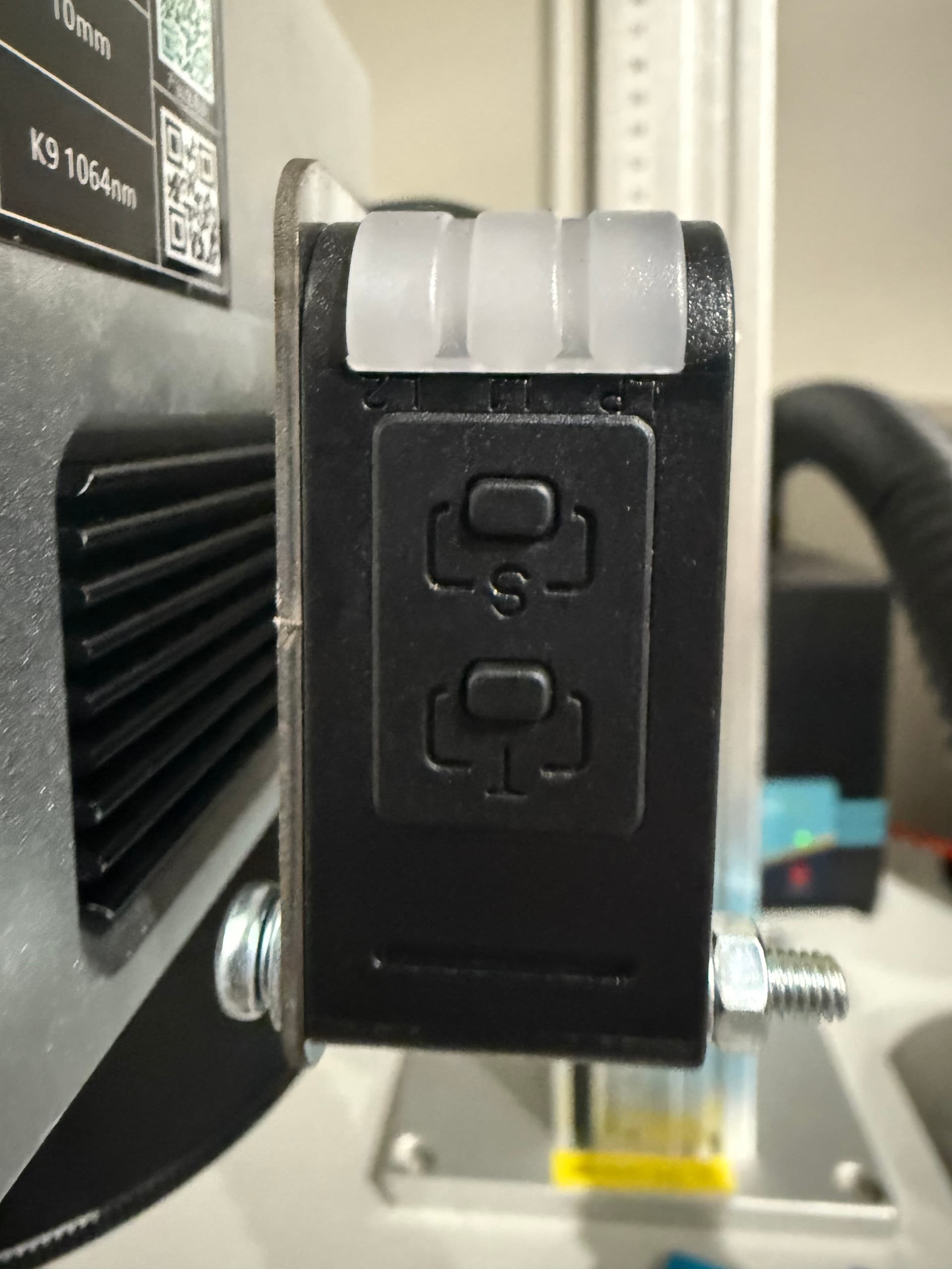
On manual models, there’s that pair of red laser pointers that converge when focused. It can only be set for one focal length and kind of a pain to recalibrate. When I changed to another lens, I couldn’t use them. I wanted to use the ruler scale on the z-lift but you have to calc the offset between the scale pointer and the actual focal height with a shorter lens, and the work height. But the offset will actually change some when you go change the lens too because the lens thickness is different. So it’s only “ballpark” and needs manual

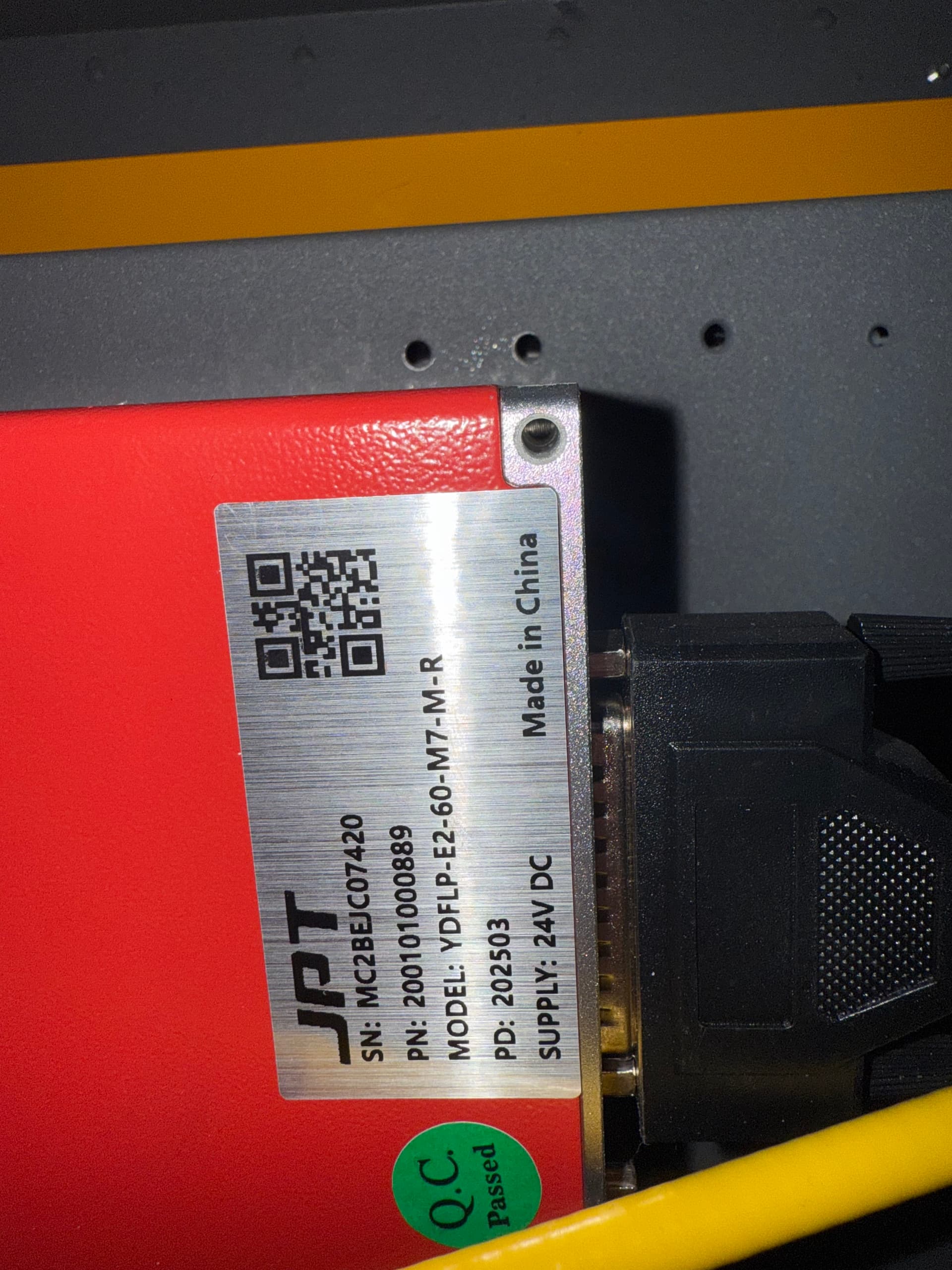
You do need the manual for “YDFLP-E2-60-M7-M-R” specifically. You can email JPT for it- in my case they wanted the exact serial number on that label too to give me a manual for it.

Reason being, there are only ~17 defined q-pulse lengths. If you enter a number that is not defined, it will round off to one that is defined. Each q-pulse has a max freq and a “cutoff frequency”- below the cutoff, the pulse profiles are fixed and adding more freq just gets you more net power (not to be confused with the “Power” field). The net power from the machine peaks at the cutoff freq. AFAIK that should be 60W for your machine if you had a power meter on the output, for any q-pulse.

But above the cutoff freq, the machine throttles back its net power output with increasing freq. AFAIK it does this by internally capping the “Power” field, and if you hadn’t entered 100% in Power anyways, it might still be under the cap- but that’s untested.

Without that mfg chart, you won’t know which pulse you’re selecting or if you’re getting limited. That will confound your attempts to do materials testing. Material testing in LB really can’t sweep q-pulse on an axis because the q-pulse types are spaced irregularly.

I can easily hit a “melt limit” on mine, esp in raster scans. If the surface temp gets too high, the beam actually stops cutting. Part of the scan line will go from bluish-white to orange and there’s not as much spark. The beam doesn’t really vaporize a chip by boiling metal, it explodes it with the shock and a chip flies off. My best understanding is if the surface is near melting, it will be too plastic and absorbs the explosion instead of throwing off a chip as a spark. It can also melt completely and flow and fill in what you’re trying to cut.

The net surface heat is a factor of 3 things- within a raster line, the overlap of heat from the last pulse or pulses leading up to it. If the pulse spacing is similar to the spot size, there is little overlap and this is minimal. Second is overlap from the heat of the prior line. It’s generally not significant if you use rotation. If you don’t use rotation and line interval is smaller than the focal spot size, then it can sometimes be very significant. And, net heating of the coin blank can happen. I’ve gone way too far and gotten them to glow. This didn’t generally happen in ranges which were actually successful at all with engraving though.

Overheating may not show up for the first few passes, until heat builds up. It it going to be worse in the early layers of 3d layers because those are almost always firing for every pixel. The behavior is really inconsistent in this range too, because the time spent to get from one raster line to the next varies depending on width.

It’s not JUST the overheating though- I see “splashing”, esp in aluminum, where the ejected particle- which is going to be a liquid state- doesn’t eject over the top, it gets blown out of the center of the mark but sticks on the edge of the cut and it just builds up and makes a rough edge. On my 300W, that was easy to do. I think it’s best to go with a smaller q-pulse to avoid this.

The 110x110 lens is probably going to be your go-to lens for coins and most other things. The Line Interval should be about 0.015-0.030. The lens’s focal spot size comes from a physics rule on lens diffraction- twice the focal length means twice the spot size. The beam can’t focus smaller than the FSS.

However, the actual Mark Spot Size (MSS) is the size of the cut made is different- a bigger pulse makes a bigger spot.

One thing it took awhile to notice is that we can cut within a single line in “single-spot mode” or “multi-spot overlap mode”- I made that up term for it, I don’t know if there’s anything to look up about it.

The length of the q-pulse in time is generally insignificant. At 7000mm/s, 100ns covers 0.0007mm, much smaller than the FSS. But the resulting MSS will be like 0.015-0.030.

Within a line, be VERY aware of pulse spacing, which is just speed/freq. In general I’ve gotten the best success with “square pattern”- pulse spacing is equal to LI.

The “single spot mode” is if you select a q-pulse that isn’t above the energy threshold that will mark the material, AND speed is high enough that the FSS doesn’t overlap, you get no mark. But you can get a mark where the pulses overlap. The first pulse in a line creates no mark, only localized heat. If speed/freq is greater than the FSS, the next pulse doesn’t overlap, so there’s a whole wide range where it does nothing. But if the next pulse does overlap, then the second pulse can make a mark where the energy of the second pulse overlaps the first. As you go higher freq and/or lower speed, 3 or more pulses can overlap within an FSS.

So far my best recommendation has roughly been:

  1. LI be the MSS, 0.015-0.030 for a 110x110 lens. So the line basically doesn’t overlap.
  2. Go “single pulse mode”, pulse spacing ( speed/freq) is the MSS. I’ve gotten some decent results with pulse spacing half that, though. But it seems worse for the amount of heat generated vs the actual chip size.
  3. Keep “Power” at 100%, and control the pulse energy primarily by q-pulse selection while keeping the speed/freq=MSS.

Rastering without rotation keep sucking. The mark made isn’t a circle with a flat bottom- it’s generally an inverted bell-curve crater, and a line is a plowed row with an inverted bell-curve cross-section. So with LI=MSS, the bottom isn’t smooth, it shows lines. And even if you have a lot of tiny layers in 3d slice mode, the lines always land in the same place (interlacing would fix this, but that feature doesn’t exist yet), so the “plowed field” effect still develops. It smoothed out if I went with like LI<(MSS/2), but then it’s slow and the heat is overlapping a lot with the last line.

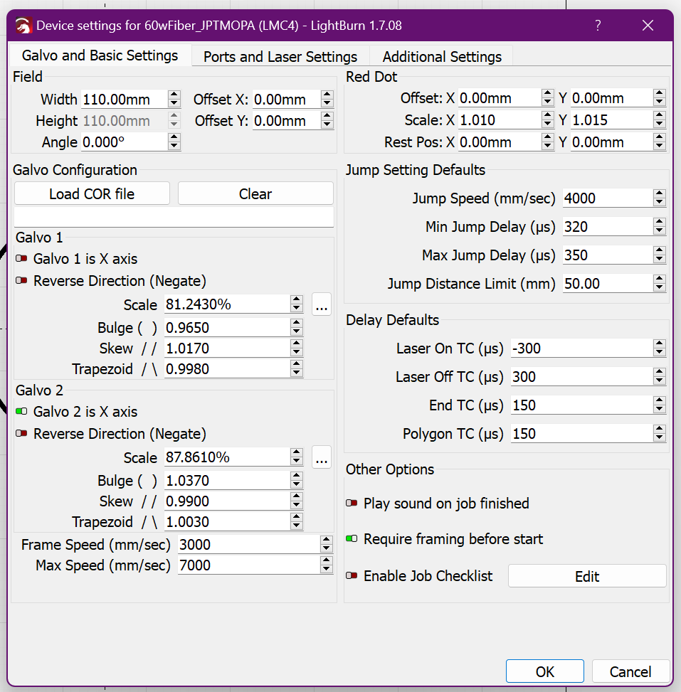
So I’m seeing rotation as essential, but you MUST have your TON/TOFF well calibrated to use rotation (or bidir). Those sync the laser fire command with mirror position. If TON/TOFF is poorly calibrated, it can still look good with no rotation/no bidir. But click “bidir” and the left and right-going lines don’t match up and it looks blurred horizontally. Rotation spreads the blur to the perpendicular axis, too.

I’ve made a lot of progress on HOW you’re supposed to calibrate TON/TOFF. All the info on how you’re supposed to do it, from every source, seems to be inaccurate and confusing and basically wrong for rastering. I developed a test that gave a super-accurate result, except I came to realize it didn’t give the same result with some changes in other params. Specifically the jump speed and jump delay are mattered- I’ve spent the day trying to understand exactly WHAT this jump is even doing, so I can figure out how it factors into calibration. It’s weird, the jump speed dramatically affects the time needed to raster, more so than would be explained by what I thought it did.

do you think i need a new control board? a non-clone one?

Danny, thanks again for your expertise. unfortunately, most of what you said went way, way, way over my head. can we take a few steps back and proceed baby-step style? also, here is a few notes for clarification:

  1. yes, i have safety goggles.

  2. i’m now under the impression that i have a clone board. im still not sure if i have the correct layout in lightburn per my devices capabilities. can you please check the screenshot below and let me know if anything is missing? If so, could the clone board be messing anything up here, or otherwise driver compatibility/recognition of features with the clone board? I’m not opposed to getting a new board, but swapping it will be an adventure for sure.

3.i will go ahead and see if i cant find a liaison/email for JPT to send me a manual.

thanks again for your help


Danny,

to complicate matters, i just found that the “JPT” setting under device settings will not allow the laser to fire. the only device setting that allows the device to fire is the “IPG_YLM” option. this seems wrong. shouldn’t i be able to set Q pulse duration? why wouldn’t the laser fire with the correct source identified?

Max Freq is capped at 200KHz???

I think that should be 5000KHz! Set it to that.

The timing constants seem weird. Jump delay of 320-350us and laser on TC of -300us sounds bananas.

I can’t give you a value, they need to be calibrated. I only know mine. Let’s try the calibration routine I came up with this week.

OK, well, first we find the focus. Put a piece of aluminum or steel in the middle of the work table. If that’s a 110x110 working area, that’s an F163 lens. The “middle” of the lens (which you can only guess at, since you can only see the bottom surface) is 163mm from the work.

There should be up/down buttons to move the Z. I don’t know how your rangefinger works and we should just start from manual. Poke at buttons and see what they do.

Lift the Z a bit low so we know which way we should go. Like, I dunno, 5mm low. Or 10mm.

Set JUMP SPEED=500.
MIN/MAX JUMP DELAY=0
JDL=10
Laser On TC=50
Lasr Off TC=225
End TC=100
Polygon TC=100

Make a small rectangle in LB, middle of the workspace, set to FILL
Set SPEED=900
POWER=100%
Freq 30
Q-pulse 200ns
Line Interval 0.03
Leave everything below that off. Click Timing, make sure it is not overriding.

This will scan quite slowly. 200ns should be enough to mark the metal with a single pulse when in focus. I only need 30ns but I have the 300W.

Put on safety glasses, hit “play”. That doesn’t actually make it start yet. You get a popup window and a red rectangle should appear on the work. If you hear a whine from the head, stop. Make sure the rectangle lands on the work.
Click “continuous”, I guess. Be ready to press “STOP”.

Start it. The laser control window on the right should show a green progress bar and it will keep firing even if you click away from the popup “play” controls.

When not in focus nothing will happen. Hold down whatever button raises the Z. Soon you will get into focus and you’ll see a bluish-green-white line engraving across the work. Go a little further and it disappears. You may feel heat on your face like you’re facing a campfire while it’s out of focus. But it’s spread out and you’re wearing safety glasses, plus this is really low power.

Go here and get the TON/TOFF timing test here, the one with the red/blue tower:
How to calibrate TCON/TCOFF for galvos (BJJCZ) - #9 by Dannym

Go back and lower the q-pulse to the smallest number that still makes a white line while focused on metal. (QMinMark). Do not touch speed or freq, QMinMark is taken when pulses don’t overlap. You need the manual to know for sure, but if it’s like other M7, valid Q-pulses are 2,4,6,9,13,20,30,45,60,80,100,150,200,250,350, and 500. 1=continuous wave and freq is unusued.

Config green layer as
SPEED=900
POWER 100%
FREQ=30 (KHz)
Q-Pulse=QMinMark

Config red and blue layers with SPEED=5000
POWER 100%
FREQ = 166.67 (KHz)
Q-pulse: QMinMark
Line Interval=0.030mm
The red will have scan angle=0, blue is scan angle=180. Leave that.

Run the test and follow the iteration instructions for setting TON and TOFF and hopefully you’ll converge on the zero line.

Pull up the LogBoolean test. Use the XOR test on top right, move it to the center of the bed and make sure there’s stock there and in focus.
Use the same settings you used on the red layer.
“bidir” off

Test. Check under microscope. The diagonal corners of the checkboard should meet at a point, not isolated and not overlapping. This should be able to do that all the way to the lower left hand corner. If it only gets 3/4 of the way there, you could try to recal TON/TOFF but you’re probably eager to see it “do something”. I won’t blame you if you wanna move towards getting something to work.

If ok, try again with “bidir” on. Hopefully similar results.

Try with 45 deg rotation, 4x passes. Check under microscope.

Let’s say a miracle occurs and it looks solid all the way down… or you don’t care about fine detail and just want to see it go. Both good.

Go get a depth map, scale to whatever size you want. US nickel is a fine coin blank in a pinch. Set to 64 passes, scan angle 0, 45 deg rotation, click “enable auto rotation”. raise your q-pulse by like 2 or 3 steps. (if it was QMinMark was 80, use 150 or 200). Everything else the same. Fire. Boom, you should have something.

64 is shallow. It can go deeper with more passes, sometimes we do 256. I do think the LI needs to stay at 0.030 for an F163. 166.67KHz at 5000mm/s means it fires a pulse at 0.030 intervals. So all the pulses are side-by-side but not overlapping. Don’t change those. If it’s pecking too hard with each mark, lower the Q-pulse rather than Power.

The speed might be able to go to higher but that might be complicated to calibrate for, and you must increase FREQ by the same amount so it still fires at 0.030mm spacing

Yep if you have a JPT that should be JPT.

Did you get a mark7cfg file with your machine?

You need to load it when you create the Machine Profile in LB.

IF you don’t have one, I’m not sure what will happen. The lens won’t be calibrated but that just warps the workspace and should be mild AFAIK.
I’d be a lot more concerned if the sign of the FIRE command is wrong and it fires only when it’s supposed to be idle. I don’t see where that’s even an option though

danny, just sent you a direct message. im at my desk on standby.

MOPA Lasers are reported to run on IPG-YLPM or JPT Or both. Mine runs either one and don’t remember what the difference was 3 years ago when testing but I ended up going with the IPG-YLPM. I switched back recently to check and didn’t see a difference, don’t remember why I chose YLPM now. After changing laser type you need to power cycle for changes to take effect, at least my laser is like that. If I change from YLPM to JPT it freezes up until the power is cycled so there is something different between them.
I wouldn’t worry about your board, unless it doesn’t work. Looking at your screenshot of machine settings looks like you have corrections from the factory in place, by all means set your frequency range 1-4000 if you need it, everything else looks good for starters. Before you start down any fine tuning, I would suggest you determine focus is correct and mark some squares small up to a little smaller then full size and measure them, and measure them corner to corner. This is easy and will tell you how good of a job they did with your factory setup. If it’s not good no reason to continue with the fine tuning, have to go back to 9 point correction and/ or scale and run those utilities first.
Get a USB microscope. Mine is 2000x but I think a good 1000 or 1200 is all that is needed. Danny’s fine tuning will really help, I’ve been messing with it in my spare time and it is squeezing the last little bit of detail and speed out of my machine. But make sure you have the basics dialed in first. No reason to evenly torque the lug nuts if the tire is flat.

thank you! Danny was awesome and walked me through all of the calibration last night. my settings are all working fine and i’m good to go!

1 Like