I am creating shapes in SolidWorks 7 for export as DXF files to import into Lightburn. The shapes are all closed in SolidWorks, and there is only one of each. Unfortunately, in the resulting DXF file, often (but not always), the lines comprising the shapes are doubled, and none of the shapes are closed. (I only know the lines are doubled and not closed because my wife can import the DXF to Illustrator on a Mac and examine it there. I don’t have Windows software in which I could edit the DXF.) When I import the DXF to Lightburn, the odd result is that long lines show up attached to the shapes; these lines extend down to the bottom of the page and cannot be deleted, because they can’t be separated from the shapes. Please see the screenshot for an example. Does anybody have an idea about how to resolve this? Thanks so much!

A few suggestions:
- upgrade to latest if you can. There are generally tweaks to import functionality that improve these types of issues although I can’t recall specifically if there was something since your release.
- In Settings->File Settings there is an option for DXF auto-close tolerance. You may want to try tweaking that to see if you can get the shapes to close.
I upgraded to the latest version of Lightburn and increased the auto-close tolerance to 1mm (too much, but just testing), but the issue persists. I wish I could afford to upgrade my ancient version of SolidWorks, but it’s prohibitively expensive, so can’t do that.
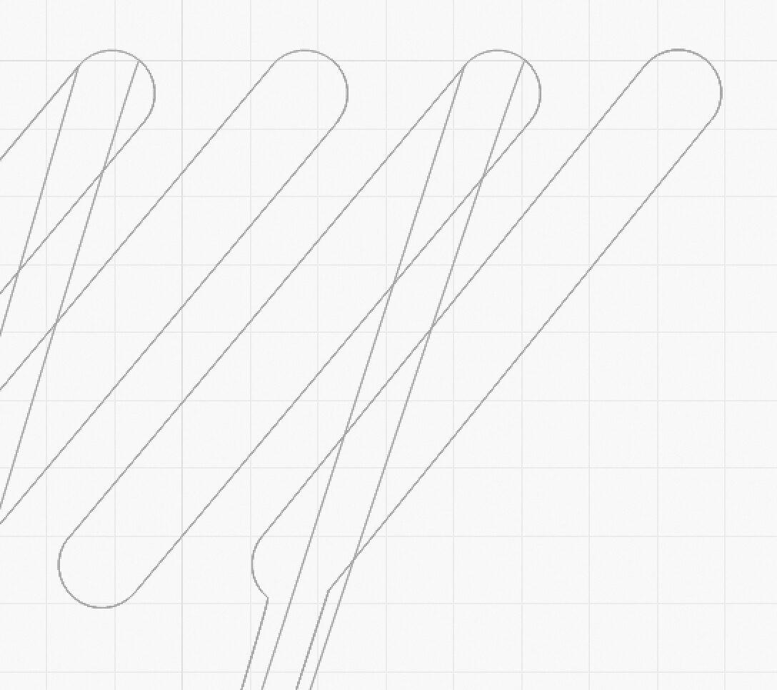
I did some experimenting and found that I could break apart the entire thing, then manually delete all the duplicate lines and the long added line segments, then select all the pieces of each of the shapes and join them to make closed shapes, but this is very tedious. Also, it won’t work for all the shapes, because even though they are all duplicates of one original, some of them end up looking like this screenshot upon import (the lower part of the right hand shape is missing altogether).
Thanks for trying to help… this forum has got so much great info!
I suggest you send the .DXF file to support@lightburnsoftware.com with a link to this Topic and ask them to see if they can figure out what’s wrong. If it’s a problem in the import process they would want to know. Or if there’s a problem in the way the file is generated they may be able to tell you how to remedy.
Okay, will do, thanks!
Can you upload the solidworks and the dxf files here, I will take a look at them for you.
Last night we discovered a setting in the Solidworks DXF export settings - when exporting the DXF from the drawing file, “enable end point merging” was unchecked; checking that fixed the problem of the shapes not being closed in a simple test file with just a square in it, but it has not fixed the problem in the DXF of these shapes. Also, the issue whereby duplicates of all the shapes appear in the DXF file persists.
Here is the DXF file of the part; I can’t upload the Solidworks file of the part or the drawing file from which the DXF was made here; I get a notice that those files don’t have authorized extensions. I uploaded them to Google Drive, though; here is a link to them (hope it’s okay to post this link in the forum)…
https://drive.google.com/drive/folders/1ophQSXH9oCH4ImPGq_NXekTAb4dg3PmA?usp=sharing
Thanks so much for looking into this.
front vent holes.DXF (99.1 KB)
I don’t have SolidWorks so can’t open the original files but based on the DXF it seems the real core problem is the duplicate lines that you’ve identified.
If that’s the case then seems like an issue at export time or could there possibly be redundant components in the original SolidWorks design?
I’ve had a look at your SW files in SW2022 and I’d say that the problem comes from the fact that the view you’re using in your export is set to ‘Wireframe’ rather than ‘Hidden Lines Removed’. This means it’s showing both the front and the back outlines. I’ve tested it by changing it to ‘Hidden Lines Removed’ and this seems to fix it, hopefully it will also fix it in the version of SW that you’re using too.
Hope this helps.
OK, just draw your sketch, save it. do not extrude cut. Save as dxf, now you should be dealing with a single view with a single layer.
berainlb - There are no redundant components in the SolidWorks file.
Marcus - I was very hopeful that this would be a solution, but nope… The view was set to Shaded, not Wireframe; I changed it to Hidden Lines Removed, but the resulting DXF file still had the duplicates and the extra lines.
Jim - If the pieces I was preparing to cut were just flat planes, I would likely use a drawing program or Lightburn to draw them. I use SolidWorks because I’m making 3D models, and most of the pieces I need to cut are far more complex than the example here; each piece contains numerous sketches, and so can’t be exported as a single non-extruded sketch. Additionally, the simple test file I made with just a non-extruded square in it, though it didn’t have the funny lines, did have a duplicate of the shape.
It seems that maybe both issues are possibly caused by the ancient version of SolidWorks. The LightBurn team suggested I export as .ai or .svg instead of .dxf, but those formats are not available in SW 2007.
If I import your file without auto-join enabled, it looks correct, but there’s at least two copies of everything, likely because you’re exporting the front and back faces of a model from a view, instead of extracting a single set of profile outlines and exporting that.
It shouldn’t be doing the weird lines to infinity though - I’ve reproduced that here and will figure out why and fix that.
For now, if you set the DXF auto-close value to zero, import, Edit > Delete Duplicates, and then Edit > Auto-Join, it behaves. The duplicate looped shapes overlapping are confusing the code that tries to connect it all together.
That’s very odd, when I opened your .slddrw file (and after pointing it at the .sldprt file) the view is definitely set to wireframe. Anyway, it doesn’t appear to make any difference with your version of SW ![]()
Other than updating SW or moving to a different CAD package I guess the easiest solution is as @LightBurn suggests and use the ‘Delete Duplicates’ command. I often have to do the same thing when I use vectors exported from CorelDraw so you’re not alone.
I am using CAD/CAM for over 30 years, and this is the first I have seen this problem with importing DXF files.
This is the origin of the issue the drawing file. if saved as dxf from the sketch extruded or not the issue does not occur. But I can’t remember if that’s an option in SW7. Are you saving dxf as flat pattern?
Jim…
@JoeSpanier - Did you have a workflow for Fusion that didn’t create the duplicate outlines? I seem to recall you dealing with this before.
Auto Join behavior has been updated to handle duplicate shapes much more cleanly.
I really appreciate the effort all of you have put into this problem. It didn’t occur to me that Solidworks was copying the front and back of an extruded object, but it must be doing it when I convert a Solidworks part to a Solidworks drawing, which has to be done before Solidworks can convert to the DXF file. It does seem strange to me that the Solidworks programmers would do that as I can’t see any reason for it and it certainly can create confusion when those 2D models are converted to G code. Ahh, I know why. It’s because the drawing can be expressed in orthographic or isometric, and both are needed for the orthographic projection. @Lightburn, it looks like you have found a work around and I will give that a try when I have a chance (currently working on another project; will get back to this as soon as possible).
Thanks again for your help.
@LightBurn it’s laid out here: Working with Fusion 360 - LightBurn Software Documentation
The main thing is don’t project the whole shape since fusion will grab all of the edges from the face you create the main sketch.
I have had similar issues using Fushion 360, so I am following this thread closely. I usually create a drawing of the 3d part for the face I need to cut or mark. That way it is accurate to scale. The resulting pdf is usually ok, although I have had issues with non closed ends as well, usually the last end modeled. I often just manually close the end after importing it